
Discussion
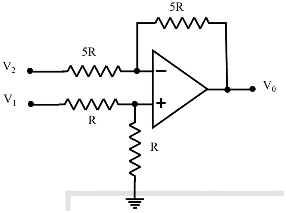
The output voltage V0 for the circuit shown in the figure is:
Answer: A
The output is \(V_0 = V_1 - V_2\).
This is a difference amplifier. The non-inverting input sits on a divider of two equal resistors R, so \(V_+ = V_1/2\). By superposition, the inverting stage has gain \(-5R/5R = -1\) for \(V_2\) and the non-inverting stage has gain \(1 + 5R/5R = 2\) for \(V_+\):
\[ \begin{aligned} V_0 &= \left(1 + \frac{5R}{5R}\right)\frac{V_1}{2} - \frac{5R}{5R}V_2 \\ &= V_1 - V_2 \end{aligned} \]
\(2(V_1 - V_2)\) forgets that the divider halves \(V_1\). \(V_1 - 2V_2\) doubles the inverting gain, and \(V_2 - V_1\) has the sign of the inputs reversed.
No comment is present. Be the first to comment.
Loading…
Post your comment
Please log in or register to post a comment.
Examination Categories
- SSC Exams
- Banking Exams
- Teaching Exams
- Civil Services Exams
- Railways Exams
- Engineering Recruitment Exams
- Defence Exams
- State Government Exams
- Police Exams
- Insurance Exams
- Nursing Exams
- Other Government Exams
- NRA CET
- PG Entrance Exams
- Campus Placement
- MBA Entrance Exams
- CUET and UG Entrance
- Judiciary Exams
- Regulatory Body Exams
- Software Development