
Discussion
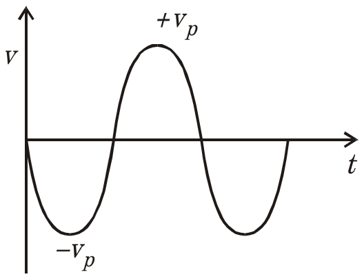
The output waveform for the following OP-Amp configuration is :

- A.
- B.
- C.

- D.

Answer: B
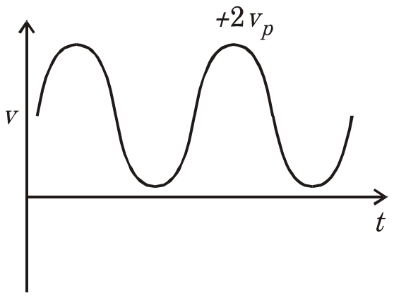
The output is waveform (B), a sine wave swinging between 0 and +2vp.
The circuit is an active positive clamper. The output node is joined to the inverting input, and the capacitor sits between the source and that node. Whenever the node tries to go below 0 V, the op-amp output swings positive, the diode conducts and charges the capacitor, holding the node at 0 V. After the first negative peak the capacitor holds vp, and the diode stays off.
\[ \begin{aligned} v_{out} &= v_{in} + v_{p} \\ 0 &\le v_{out} \le 2v_{p} \end{aligned} \]
Waveform (A) is the input unchanged, (C) is a negative clamper, which needs the diode reversed, and (D) is a clipped shape that no clamper produces.
Post your comment
Please log in or register to post a comment.
Examination Categories
- SSC Exams
- Banking Exams
- Teaching Exams
- Civil Services Exams
- Railways Exams
- Engineering Recruitment Exams
- Defence Exams
- State Government Exams
- Police Exams
- Insurance Exams
- Nursing Exams
- Other Government Exams
- NRA CET
- PG Entrance Exams
- Campus Placement
- MBA Entrance Exams
- CUET and UG Entrance
- Judiciary Exams
- Regulatory Body Exams
- Software Development