
Discussion
For the given clamper circuit, the diode is ideal.
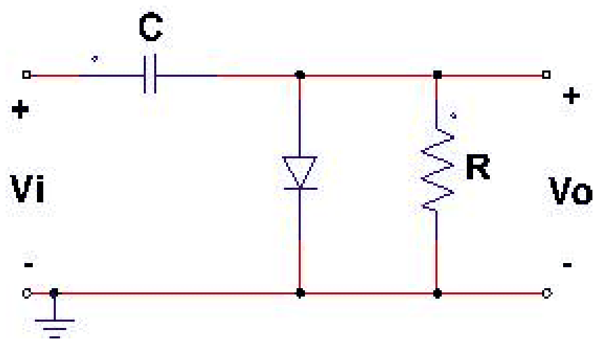
The input Vi is:
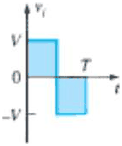
The output Vo is:
- A.

- B.

- C.

- D.
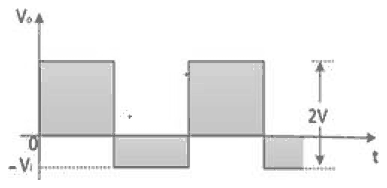
Answer: C
The capacitor in series charges through the diode, and the clamper shifts the dc level of the input without changing its shape. The diode is connected with its anode at the output node, so it conducts when the output tries to go positive. During the first half cycle (input \(+V\)) the diode conducts and the capacitor charges to \(V\), keeping the output at about 0 V. When the input falls to \(-V\) the diode is off and the output is the input minus the capacitor voltage, \(-V - V = -2V\).
So the output is a square wave between 0 and \(-2V\), which is figure (C). Figure (A) and (B) swing positive, so they would need the diode reversed, and figure (D) is the input itself without a shift. The answer is option C.
Post your comment
Please log in or register to post a comment.
Examination Categories
- SSC Exams
- Banking Exams
- Teaching Exams
- Civil Services Exams
- Railways Exams
- Engineering Recruitment Exams
- Defence Exams
- State Government Exams
- Police Exams
- Insurance Exams
- Nursing Exams
- Other Government Exams
- NRA CET
- PG Entrance Exams
- Campus Placement
- MBA Entrance Exams
- CUET and UG Entrance
- Judiciary Exams
- Regulatory Body Exams
- Software Development