
Discussion
For the given circuit, the diode is ideal.
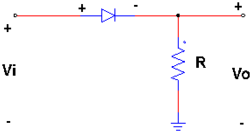
The input to this circuit is:
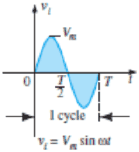
The output voltage \(V_o\) from \(T/2\) to \(T\) will be:
Answer: A
The circuit is a half wave rectifier: the ideal diode is in series with the load resistor. The diode conducts when the anode is positive with respect to the cathode, that is during the positive half cycle (0 to \(T/2\)), when the output follows the input.
From \(T/2\) to \(T\) the input is negative, so the diode is reverse biased and acts as an open circuit. No current flows through \(R\), and so the output voltage \(V_o = iR = 0\). The output is zero, option A. The values \(V_m\) and \(V_m/2\) would be the output during the positive half, and \(-V_m\) would appear only if the diode were short circuited, but then it would appear across the diode, not the load.
Post your comment
Please log in or register to post a comment.
Examination Categories
- SSC Exams
- Banking Exams
- Teaching Exams
- Civil Services Exams
- Railways Exams
- Engineering Recruitment Exams
- Defence Exams
- State Government Exams
- Police Exams
- Insurance Exams
- Nursing Exams
- Other Government Exams
- NRA CET
- PG Entrance Exams
- Campus Placement
- MBA Entrance Exams
- CUET and UG Entrance
- Judiciary Exams
- Regulatory Body Exams
- Software Development