
Discussion
The symbols C, D, \(V_{in}\) and \(V_{0}\) shown in the figure denote capacitor, ideal diode, input voltage and output voltage, respectively.
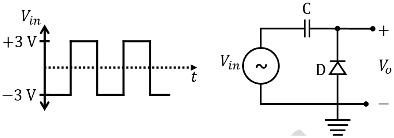
Which one of the following output waveforms \((V_{0})\) is correct for the given input waveform \((V_{in})\)?
- A.
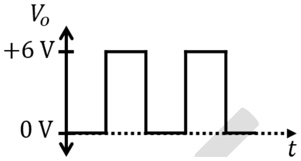
- B.
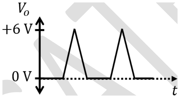
- C.
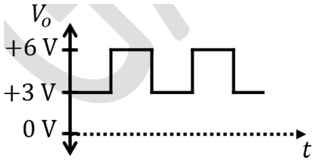
- D.
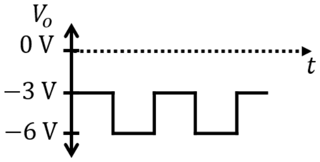
Answer: A
The output is a square wave between 0 V and +6 V (A).
This is a positive clamper. The diode runs from ground (anode) to the output (cathode), so it conducts whenever the output tries to go below 0 V. During the -3 V half of the input the diode conducts and the capacitor charges to 3 V, with its output side 3 V above its input side. Afterwards the diode stays off and the capacitor simply adds 3 V to the input:
\[ \begin{aligned} V_{0} &= V_{in} + 3\ \text{V} \\ -3\ \text{V} &\to 0\ \text{V}, \quad +3\ \text{V} \to +6\ \text{V} \end{aligned} \]
The shape of the input is preserved, so triangular pulses (B) are wrong. A wave between +3 V and +6 V (C) has the wrong shift and amplitude, and a wave between -3 V and -6 V (D) is what a clamper with the diode reversed would give, and with a halved swing.
Post your comment
Please log in or register to post a comment.
Examination Categories
- SSC Exams
- Banking Exams
- Teaching Exams
- Civil Services Exams
- Railways Exams
- Engineering Recruitment Exams
- Defence Exams
- State Government Exams
- Police Exams
- Insurance Exams
- Nursing Exams
- Other Government Exams
- NRA CET
- PG Entrance Exams
- Campus Placement
- MBA Entrance Exams
- CUET and UG Entrance
- Judiciary Exams
- Regulatory Body Exams
- Software Development