
Discussion
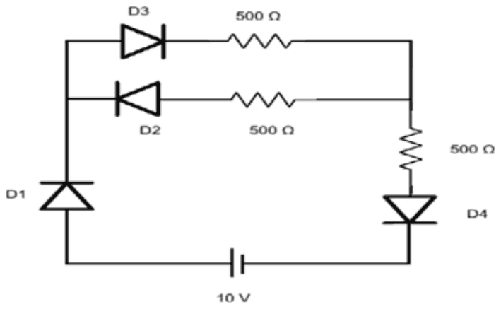
Four ideal diodes are connected as shown then the current drawn from the battery is
Answer: B
The current drawn is 10 mA.
The battery's longer plate, its positive terminal, faces diode D1, so current leaves it towards D1, whose arrow points up the left side. D1 conducts. At the junction the current can take D3 or D2. D3 points from the left to the right, so it conducts; D2 points the other way, so it is reverse biased and carries nothing. The current therefore goes through D3 and its 500 Ω resistor, comes down through the third 500 Ω resistor and passes D4, whose arrow points downward, so D4 conducts, and returns to the battery.
Ideal diodes that conduct have no drop, so the circuit is two 500 Ω resistors in series:
\[ \begin{aligned} I &= \frac{V}{R} = \frac{10}{500 + 500} \\ &= 0.01\ \text{A} = 10\ \text{mA} \end{aligned} \]
Zero would need a blocked diode in the only path, which is not the case. 20 mA would need both upper branches to conduct, and 50 or 100 mA would need resistances of 200 or 100 Ω, far below what the circuit has.
Post your comment
Please log in or register to post a comment.
Examination Categories
- SSC Exams
- Banking Exams
- Teaching Exams
- Civil Services Exams
- Railways Exams
- Engineering Recruitment Exams
- Defence Exams
- State Government Exams
- Police Exams
- Insurance Exams
- Nursing Exams
- Other Government Exams
- NRA CET
- PG Entrance Exams
- Campus Placement
- MBA Entrance Exams
- CUET and UG Entrance
- Judiciary Exams
- Regulatory Body Exams
- Software Development