
Discussion
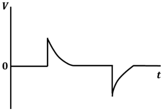
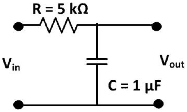
An input voltage in the form of a square wave of frequency 1 kHz is given to a circuit, which results in the output shown schematically below. Which one of the following options is the CORRECT representation of the circuit?
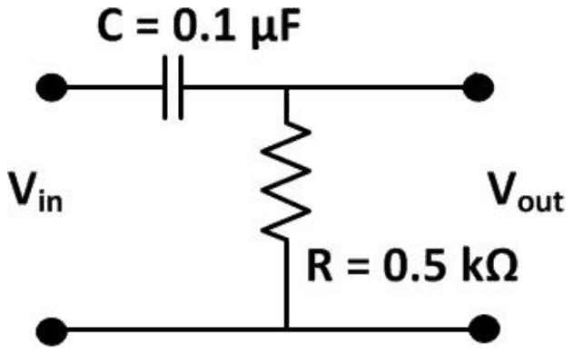
- A.
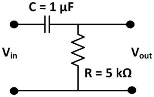
- B.
- C.
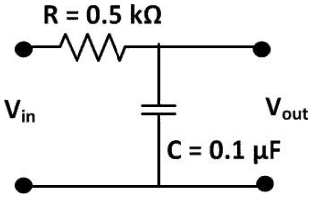
- D.
Answer: A
The circuit is (A): a series 0.1 μF capacitor with a shunt 0.5 kΩ resistor, a differentiator with a short time constant.
The output is a sharp spike at each edge of the square wave that dies away to zero long before the next edge. That is the response of a high-pass RC circuit (capacitor in series, output across the resistor) whose time constant is much shorter than the half period.
\[ \begin{aligned} \tau_{A} &= 0.5\ \text{k}\Omega \times 0.1\ \mu\text{F} = 50\ \mu\text{s} \\ T/2 &= 0.5\ \text{ms} \end{aligned} \]
With \(\tau \ll T/2\) each spike decays fully, as drawn. Circuit (B) has the same layout but \(\tau = 5\) ms, ten times the half period, so its output would barely decay and look like a slightly tilted square wave. Circuits (C) and (D) take the output across the capacitor; these low-pass integrators give smoothed or ramp-like versions of the square wave, not spikes.
Post your comment
Please log in or register to post a comment.
Examination Categories
- SSC Exams
- Banking Exams
- Teaching Exams
- Civil Services Exams
- Railways Exams
- Engineering Recruitment Exams
- Defence Exams
- State Government Exams
- Police Exams
- Insurance Exams
- Nursing Exams
- Other Government Exams
- NRA CET
- PG Entrance Exams
- Campus Placement
- MBA Entrance Exams
- CUET and UG Entrance
- Judiciary Exams
- Regulatory Body Exams
- Software Development