
Discussion
Consider the following circuit:
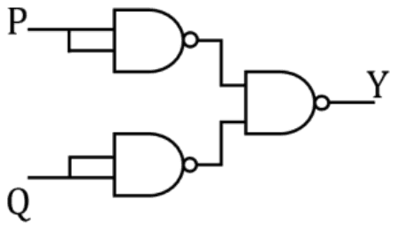
Suppose the input signal P is
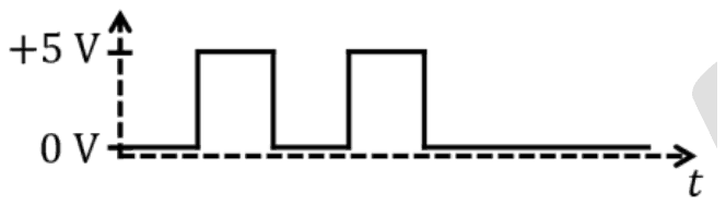
and the input signal Q is
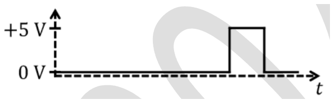
Which one of the following output signals is correct?
- A.

- B.
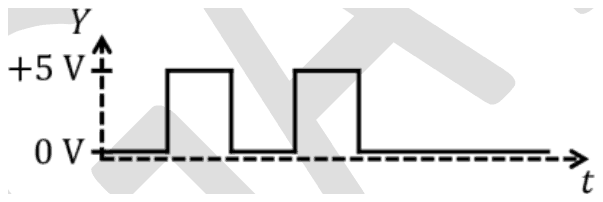
- C.
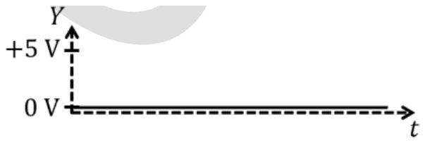
- D.
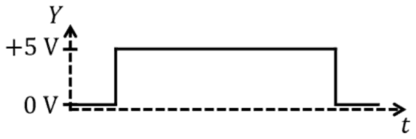
Answer: A
The output is three pulses (A).
A NAND gate with both inputs tied together is an inverter, so the first two gates give P′ and Q′. The final NAND gives
\[ Y = (P' \cdot Q')' = P + Q \]
by De Morgan's law. So Y is high whenever P or Q is high. P has two pulses early on and Q one pulse later, at a time when P is low, so Y shows all three pulses.
Two pulses (B) would be P alone, ignoring Q. A flat zero (C) is P AND Q, which is never high since the pulses do not overlap. One long pulse (D) does not follow from any combination of these inputs.
No comment is present. Be the first to comment.
Loading…
Post your comment
Please log in or register to post a comment.
Examination Categories
- SSC Exams
- Banking Exams
- Teaching Exams
- Civil Services Exams
- Railways Exams
- Engineering Recruitment Exams
- Defence Exams
- State Government Exams
- Police Exams
- Insurance Exams
- Nursing Exams
- Other Government Exams
- NRA CET
- PG Entrance Exams
- Campus Placement
- MBA Entrance Exams
- CUET and UG Entrance
- Judiciary Exams
- Regulatory Body Exams
- Software Development