
Discussion
Considering the circuit and the associated signals measured at different pins (numbered as 1, 2, 3, 4, 5) shown in the figure, the correct option is
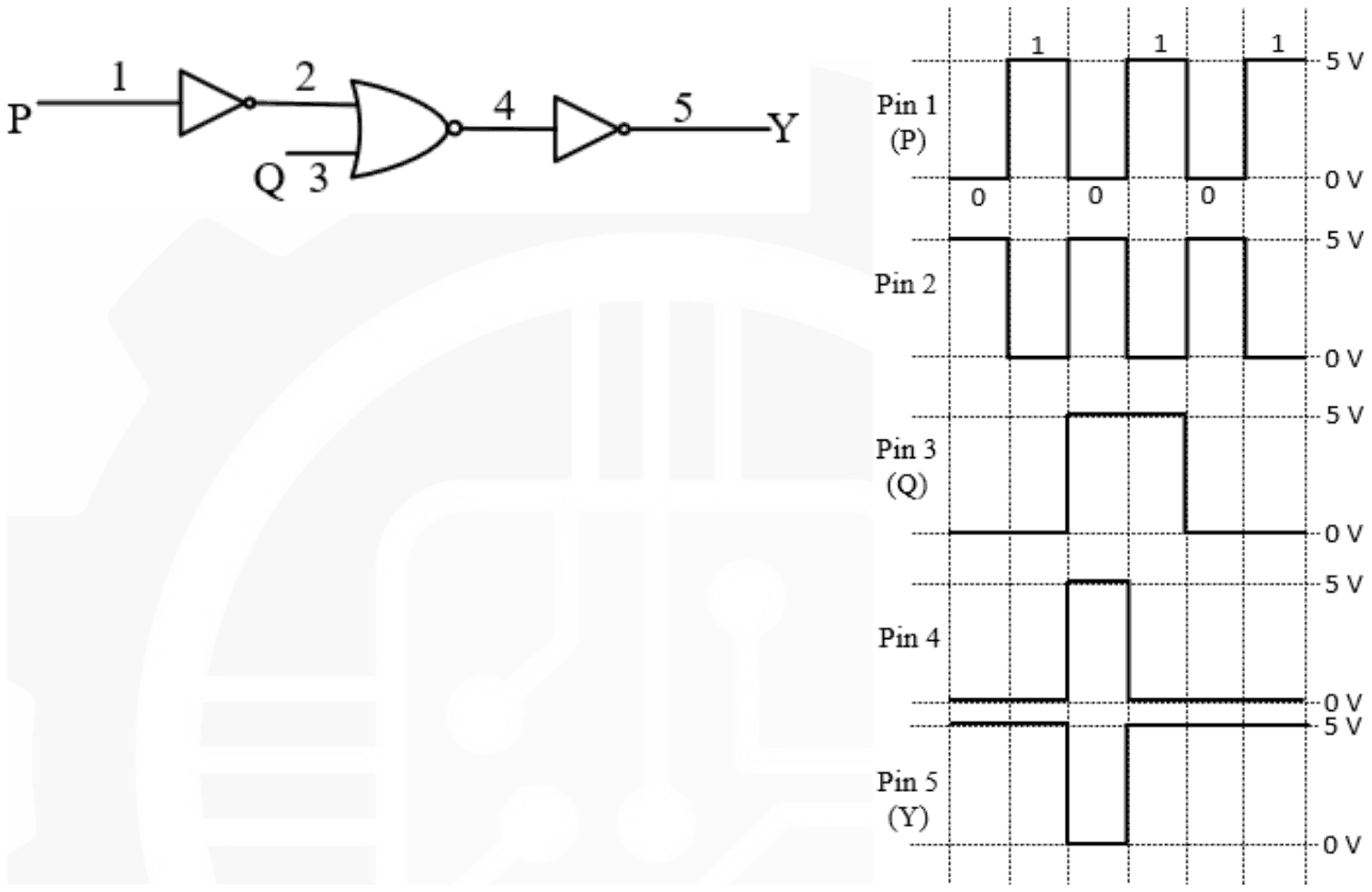
| Interval | 1 | 2 | 3 | 4 | 5 | 6 |
|---|---|---|---|---|---|---|
| Pin 1 (P) | 0 | 1 | 0 | 1 | 0 | 1 |
| Pin 2 | 1 | 0 | 1 | 0 | 1 | 0 |
| Pin 3 (Q) | 0 | 0 | 1 | 1 | 0 | 0 |
| Pin 4 | 0 | 0 | 1 | 0 | 0 | 0 |
| Pin 5 (Y) | 1 | 1 | 0 | 1 | 1 | 1 |
Answer: B
The NOR gate is faulty.
Check each gate against its own inputs. The first NOT gate is fine: pin 2 (1, 0, 1, 0, 1, 0) is the inverse of pin 1 (0, 1, 0, 1, 0, 1). The output NOT gate is fine: pin 5 (1, 1, 0, 1, 1, 1) is the inverse of pin 4 (0, 0, 1, 0, 0, 0).
A working NOR gate gives 1 only when both inputs are 0. With pin 2 = 1, 0, 1, 0, 1, 0 and pin 3 = 0, 0, 1, 1, 0, 0, both are 0 in intervals 2 and 6, so pin 4 should read 0, 1, 0, 0, 0, 1. It actually reads 0, 0, 1, 0, 0, 0, high only when both inputs are 1, which is AND behaviour. So the NOR gate alone is at fault, and the options blaming either NOT gate, or both the NOR and the output NOT gate, are ruled out by the checks above.
Post your comment
Please log in or register to post a comment.
Examination Categories
- SSC Exams
- Banking Exams
- Teaching Exams
- Civil Services Exams
- Railways Exams
- Engineering Recruitment Exams
- Defence Exams
- State Government Exams
- Police Exams
- Insurance Exams
- Nursing Exams
- Other Government Exams
- NRA CET
- PG Entrance Exams
- Campus Placement
- MBA Entrance Exams
- CUET and UG Entrance
- Judiciary Exams
- Regulatory Body Exams
- Software Development