
Discussion
In a 2-to-1 multiplexer as shown below, the output X = A0 if C = 0, and X = A1 if C = 1.
(Figure: a block with data inputs A0 and A1, select input C and output X.)
Which one of the following is the correct implementation of this multiplexer?
- A.
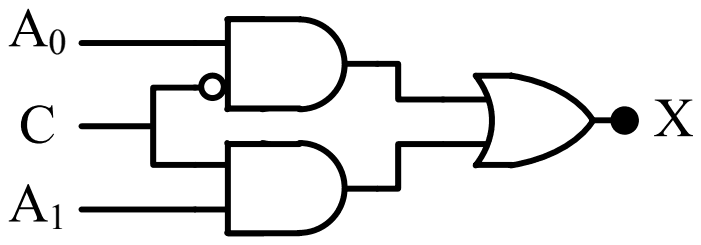
- B.
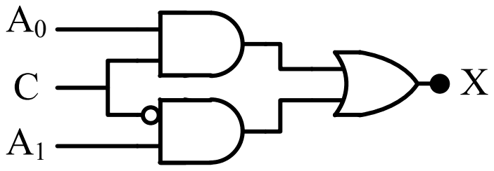
- C.
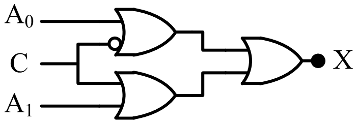
- D.
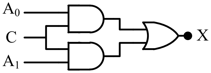
Answer: A
The correct implementation is circuit (A).
A 2-to-1 multiplexer computes
\[ X = A_{0}\bar{C} + A_{1}C \]
so one AND gate must pass \(A_{0}\) when \(C = 0\), which needs \(C\) inverted at that gate, and the other must pass \(A_{1}\) when \(C = 1\), with \(C\) uninverted. An OR gate combines them. Circuit (A) has the inversion bubble on the \(C\) input of the \(A_{0}\) gate: exactly this.
Circuit (B) inverts \(C\) at the \(A_{1}\) gate, so it selects \(A_{1}\) when \(C = 0\), the reverse of the specification. Circuit (D) has no inversion, so both gates are enabled together by \(C = 1\) and both disabled by \(C = 0\). Circuit (C) uses OR gates in the first stage, which pass a 1 whenever either input is 1, so it cannot select one input.
Post your comment
Please log in or register to post a comment.
Examination Categories
- SSC Exams
- Banking Exams
- Teaching Exams
- Civil Services Exams
- Railways Exams
- Engineering Recruitment Exams
- Defence Exams
- State Government Exams
- Police Exams
- Insurance Exams
- Nursing Exams
- Other Government Exams
- NRA CET
- PG Entrance Exams
- Campus Placement
- MBA Entrance Exams
- CUET and UG Entrance
- Judiciary Exams
- Regulatory Body Exams
- Software Development