
Discussion
The voltage transfer function of the network shown in the figure below is :
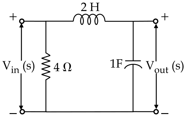
Answer: C
The transfer function is \(\frac{1}{1 + 2s^{2}}\).
The 4 Ω resistor is connected directly across the input, so it carries its own current but does not change the voltage applied to the rest of the network. The output is then a voltage divider of the 2 H inductor and the 1 F capacitor:
\[ \begin{aligned} \frac{V_{out}}{V_{in}} &= \frac{1/sC}{sL + 1/sC} = \frac{1}{1 + s^{2}LC} \\ &= \frac{1}{1 + 2s^{2}} \end{aligned} \]
\(\frac{1}{1 + 2s}\) would come from a resistor and capacitor, not an inductor and capacitor. \(1 + 4s\) and \(6 - s\) grow with frequency, which a passive divider of this kind cannot do.
No comment is present. Be the first to comment.
Loading…
Post your comment
Please log in or register to post a comment.
Examination Categories
- SSC Exams
- Banking Exams
- Teaching Exams
- Civil Services Exams
- Railways Exams
- Engineering Recruitment Exams
- Defence Exams
- State Government Exams
- Police Exams
- Insurance Exams
- Nursing Exams
- Other Government Exams
- NRA CET
- PG Entrance Exams
- Campus Placement
- MBA Entrance Exams
- CUET and UG Entrance
- Judiciary Exams
- Regulatory Body Exams
- Software Development