
Instruction
- Total number of questions : 20
- Time allotted : 30:00 Minutes:Seconds.
- Each question carry 1 mark, no negative marks.
- DO NOT refresh the page.
- All the best
Control Systems [ Question No: 1 To 20 ] :
Match the pairs :
| Set I | Set II |
|---|---|
| (a) Gear train rotational transformer | (i) \(V_{2}(s) = K_{t}\, w(s)\) |
| (b) Tachometer velocity sensor | (ii) \(\theta_{L} = n \theta_{m}\) or \(w_{L} = n w_{n}\) |
| (c) DC amplifier | (iii) \(\frac{X_{o}(s)}{X_{m}(s)} = \frac{-s^{2}}{s^{2} + (b/m)s + k/m}\) |
| (d) Acceleration sensor | (iv) \(K_{a}/(s\tau + 1)\) |
Disadvantage of an electronic control system is :
Transient analysis in a control system means :
The order and type of the system shown in the following figure is :

A PI controller increases :
Given below are two statements :
Statement I : The phase lag network allow to pass high frequencies and low frequencies are attenuated.
Statement II : The steady state accuracy can be improved by using phase lead network.
In the light of the above statements, choose the most appropriate answer from the options given below.
A feedback control system has open loop transfer function is :
\[ G(s) = \frac{5(s+3)(s+5)}{s^{2}(s+1)(s^{2}+7s+12)} \]
The system order and type number respectively is :
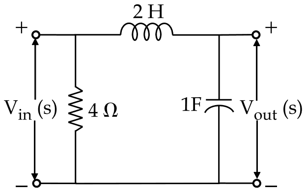
The voltage transfer function of the network shown in the figure below is :
For an under damped second order control system, if damping increases, the settling time :
The Bode magnitude plot of a certain control system shows the gain to be -20 dB at the phase cross over frequency. What is the gain margin expressed as a ratio ?
The term jω on Log magnitude plot has a slope of __________.
Match List I with List II and select the correct answer using codes given below :
| List I (Characteristic Equation of the System) | List II (Stability of the System) |
|---|---|
| (a) \(s^{5} + s^{4} + 2s^{3} + 2s^{2} + 3s + 15 = 0\) | (i) marginally stable |
| (b) \(s^{6} + 2s^{5} + 8s^{4} + 12s^{3} + 20s^{2} + 16s + 16 = 0\) | (ii) unstable |
| (c) G(s) H(s) = 10/s (s + 2) (s + 5) | (iii) stable |
| (d) \(G(s) = \dfrac{s + 5}{s^{2} + 4s + 9}\) | (iv) phase angle of the system varies between 0° and -90°. |
The characteristic equation for a feedback control system is Q(s) = s3 + 13s2 + 30s + k = 0.
The range of k for a stable system is :
The open loop transfer function of a unity feedback control system has open loop transfer function as: \(G(s) = 10 / (s(1 + 0.02s)(1 + 0.2s))\).
The phase at the gain crossover frequency is \(-150^\circ\). The gain at phase crossover frequency is \(+15\) dB.
What is the value of phase margin and gain margin?
Find the corner frequencies if the transfer function is given as:
\(G(s) = \dfrac{10}{s(1 + 0.4s)(1 + 0.1s)}\).
Which of the following terms is NOT a frequency domain specification?
The response of a system is obtained as \(C(t) = 1 + 0.2\exp(-60t) - 1.2\exp(-10t)\), when subjected to a unit-step input. The close loop transfer function is:
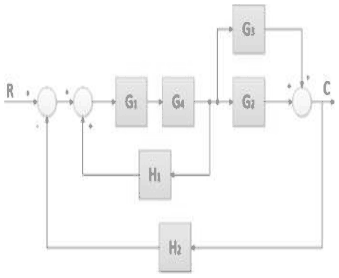
Which of the following options is the correct reduced block diagram (complete reduction) of the given block diagram?
For the given block diagram, which of the following options is a correct replacement for moving a summing point ahead of a block?

The close loop transfer function of for a unity feedback system is \(C(s)/R(s) = K/(s^2 + 4s + K)\).
The correct statement is:
Total number of questions : 20
Number of answered questions : 0
Number of unanswered questions : 20
Control Systems [ Question No: 1 To 20 ] :
Match the pairs :
| Set I | Set II |
|---|---|
| (a) Gear train rotational transformer | (i) \(V_{2}(s) = K_{t}\, w(s)\) |
| (b) Tachometer velocity sensor | (ii) \(\theta_{L} = n \theta_{m}\) or \(w_{L} = n w_{n}\) |
| (c) DC amplifier | (iii) \(\frac{X_{o}(s)}{X_{m}(s)} = \frac{-s^{2}}{s^{2} + (b/m)s + k/m}\) |
| (d) Acceleration sensor | (iv) \(K_{a}/(s\tau + 1)\) |
Your Answer : (Not Answered)
Correct Answer : A
The correct code is (a)-(ii), (b)-(i), (c)-(iv), (d)-(iii).
A gear train acts as a rotational transformer: the load angle is the motor angle times the gear ratio, \(\theta_{L} = n\theta_{m}\) (ii). A tachometer produces a voltage proportional to shaft speed, \(V_{2}(s) = K_{t}\,\omega(s)\) (i). A dc amplifier is modelled as a gain with a single time constant, \(K_{a}/(s\tau + 1)\) (iv). An accelerometer is a mass-spring-damper, giving the second-order ratio with \(-s^{2}\) in the numerator (iii).
The other codes give the tachometer the first-order amplifier model or match the gear train to the second-order accelerometer equation.
Disadvantage of an electronic control system is :
Your Answer : (Not Answered)
Correct Answer : C
The keyed disadvantage is that electronic control is susceptible to fire risk.
Compared with pneumatic control, which uses only compressed air and is intrinsically safe, electronic control systems carry electrical energy into the plant. In hazardous areas, such as refineries and chemical plants with flammable gases, a spark from electrical equipment can ignite the atmosphere, so electronic instruments need explosion-proof or intrinsically safe designs.
Electronic controllers draw very little current, are generally cheaper and more flexible than pneumatic ones, and are not inherently affected by the seasons, so the other options are not their characteristic disadvantage.
Transient analysis in a control system means :
Your Answer : (Not Answered)
Correct Answer : C
The keyed meaning is analysing the system with an infinite frequency spectrum.
Transient analysis studies how a control system responds to sudden inputs, such as a unit step or impulse, before it settles to steady state: rise time, overshoot and settling time. Such inputs change abruptly, and their spectrum extends over all frequencies; a unit impulse has a flat spectrum to infinite frequency. Testing with them therefore excites the system across its whole frequency range at once.
Subjecting the system to a short period or a momentary high voltage describes a stress test, not transient analysis, and calling it merely 'a mathematical tool' does not say what is analysed.
The order and type of the system shown in the following figure is :
Your Answer : (Not Answered)
Correct Answer : A
The system is Type : 1, Order : 3.
The open loop transfer function is the product of the forward and feedback blocks:
\[ G(s)H(s) = \frac{k_{1}k_{2}}{s(s^{2} + 4s + 16)} \]
The type is the number of open loop poles at the origin: one factor of s, so type 1. The order is the degree of the characteristic polynomial, s(s2 + 4s + 16) + k1k2, which is 3.
Type 2 or 3 would need more integrators, and order 1 or 2 ignores either the quadratic forward block or the integrator in the feedback path.
A PI controller increases :
Your Answer : (Not Answered)
Correct Answer : D
A PI controller increases the type and order of the system by 1.
A PI controller has the transfer function
\[ \begin{aligned} G_{c}(s) &= K_{p} + \frac{K_{i}}{s} \\ &= \frac{K_{p}s + K_{i}}{s} \end{aligned} \]
It adds a pole at the origin and a zero. The extra pole at the origin raises the type of the system by 1, which is why integral action removes the steady state error to a step. The extra pole also raises the order of the characteristic equation by 1.
Options naming only the type or only the order are each half of the effect, and the option saying both decrease has the effect backwards.
Given below are two statements :
Statement I : The phase lag network allow to pass high frequencies and low frequencies are attenuated.
Statement II : The steady state accuracy can be improved by using phase lead network.
In the light of the above statements, choose the most appropriate answer from the options given below.
Your Answer : (Not Answered)
Correct Answer : A
Both Statement I and Statement II are false.
Statement I is false: a phase lag network behaves as a low-pass filter. It passes low frequencies and attenuates high frequencies, which is the reverse of what the statement says.
Statement II is false: steady-state accuracy is improved by the lag network, which raises the low-frequency gain and so reduces the steady-state error. A phase lead network improves the transient response, increasing bandwidth and speed of response, not the steady-state accuracy. Since both statements are wrong, every option calling either one true is ruled out.
A feedback control system has open loop transfer function is :
\[ G(s) = \frac{5(s+3)(s+5)}{s^{2}(s+1)(s^{2}+7s+12)} \]
The system order and type number respectively is :
Your Answer : (Not Answered)
Correct Answer : B
The order and type are 5 and 2.
The order is the highest power of \(s\) in the denominator of the transfer function. Here the denominator is \(s^{2}(s+1)(s^{2} + 7s + 12)\), of degree \(2 + 1 + 2 = 5\).
The type is the number of open-loop poles at the origin, the power of the factor \(s\) alone in the denominator: \(s^{2}\), so type 2. A type 2 system has zero steady-state error to step and ramp inputs.
The options with order 2 count only the \(s^{2}\) factor, and 2, 5 gives the two numbers in the wrong order.
The voltage transfer function of the network shown in the figure below is :
Your Answer : (Not Answered)
Correct Answer : C
The transfer function is \(\frac{1}{1 + 2s^{2}}\).
The 4 Ω resistor is connected directly across the input, so it carries its own current but does not change the voltage applied to the rest of the network. The output is then a voltage divider of the 2 H inductor and the 1 F capacitor:
\[ \begin{aligned} \frac{V_{out}}{V_{in}} &= \frac{1/sC}{sL + 1/sC} = \frac{1}{1 + s^{2}LC} \\ &= \frac{1}{1 + 2s^{2}} \end{aligned} \]
\(\frac{1}{1 + 2s}\) would come from a resistor and capacitor, not an inductor and capacitor. \(1 + 4s\) and \(6 - s\) grow with frequency, which a passive divider of this kind cannot do.
For an under damped second order control system, if damping increases, the settling time :
Your Answer : (Not Answered)
Correct Answer : A
The settling time decreases.
For an underdamped second-order system the response settles within an envelope \(e^{-\zeta\omega_{n}t}\), and the settling time on the 2% criterion is about
\[ t_{s} \approx \frac{4}{\zeta\omega_{n}} \]
For a fixed natural frequency \(\omega_{n}\), a larger damping ratio \(\zeta\) makes the envelope decay faster, so \(t_{s}\) falls. It varies inversely with \(\zeta\), not with its square, and it is certainly affected by damping.
The Bode magnitude plot of a certain control system shows the gain to be -20 dB at the phase cross over frequency. What is the gain margin expressed as a ratio ?
Your Answer : (Not Answered)
Correct Answer : C
The gain margin is 10.
Gain margin is how much the loop gain can be multiplied at the phase crossover frequency before the system reaches instability. If the gain there is -20 dB, the gain margin is +20 dB. Converting decibels to a magnitude ratio:
\[ 20 \log_{10} \text{GM} = 20 \Rightarrow \text{GM} = 10 \]
Equivalently, the loop gain at phase crossover is 0.1, and the gain margin is its reciprocal, 10. 20 is the value in decibels, not the ratio; 1 would mean the system is on the edge of instability, and 5 has no basis.
The term jω on Log magnitude plot has a slope of __________.
Your Answer : (Not Answered)
Correct Answer : A
The slope is 20 dB/decade.
The magnitude of \(j\omega\) is \(\omega\), so on the log magnitude plot it contributes \(20\log_{10}\omega\) dB. Each tenfold increase in \(\omega\) adds 20 dB: a straight line of slope +20 dB/decade passing through 0 dB at \(\omega = 1\).
6 dB/decade confuses the decade with the octave: +20 dB/decade is the same as about +6 dB/octave. The negative slopes, −20 dB/decade and −6 dB/octave, belong to the pole \(1/j\omega\), not to the zero \(j\omega\).
Match List I with List II and select the correct answer using codes given below :
| List I (Characteristic Equation of the System) | List II (Stability of the System) |
|---|---|
| (a) \(s^{5} + s^{4} + 2s^{3} + 2s^{2} + 3s + 15 = 0\) | (i) marginally stable |
| (b) \(s^{6} + 2s^{5} + 8s^{4} + 12s^{3} + 20s^{2} + 16s + 16 = 0\) | (ii) unstable |
| (c) G(s) H(s) = 10/s (s + 2) (s + 5) | (iii) stable |
| (d) \(G(s) = \dfrac{s + 5}{s^{2} + 4s + 9}\) | (iv) phase angle of the system varies between 0° and -90°. |
Your Answer : (Not Answered)
Correct Answer : A
The correct matching is a-ii, b-i, c-iii, d-iv.
- (a) In the Routh array of s5 + s4 + 2s3 + 2s2 + 3s + 15, the s3 row starts with zero (2 - 2 = 0); replacing it by a small ε gives two sign changes in the first column, so two roots lie in the right half plane: unstable (ii).
- (b) The Routh array of the sixth-order polynomial produces a row of zeros whose auxiliary polynomial has roots on the imaginary axis, with no sign change in the first column: marginally stable (i).
- (c) With GH = 10/s(s + 2)(s + 5), the characteristic equation is s3 + 7s2 + 10s + 10 = 0; since \(7 imes 10 = 70 \gt 10\), all roots are in the left half plane: stable (iii).
- (d) G(s) = (s + 5)/(s2 + 4s + 9) has phase 0° at zero frequency and approaches -90° at high frequency, since it has one more pole than zero (iv).
The other codes call the polynomial with a right-half-plane pair marginally stable or the third-order loop unstable, which the Routh test rules out.
The characteristic equation for a feedback control system is Q(s) = s3 + 13s2 + 30s + k = 0.
The range of k for a stable system is :
Your Answer : (Not Answered)
Correct Answer : A
The system is stable for \(0 \lt k \lt 390\).
Build the Routh array for \(s^{3} + 13s^{2} + 30s + k\):
\[ \begin{aligned} s^{3}&: \quad 1 \quad 30 \\ s^{2}&: \quad 13 \quad k \\ s^{1}&: \quad \frac{13 \times 30 - k}{13} \\ s^{0}&: \quad k \end{aligned} \]
Every entry of the first column must be positive. The \(s^{0}\) row needs \(k \gt 0\), and the \(s^{1}\) row needs \(390 - k \gt 0\), so \(0 \lt k \lt 390\). At \(k = 390\) the \(s^{1}\) row vanishes and the system oscillates.
The other ranges are built from the coefficients themselves (13 and 30) or drop a factor of ten (39); none comes from the stability condition.
The open loop transfer function of a unity feedback control system has open loop transfer function as: \(G(s) = 10 / (s(1 + 0.02s)(1 + 0.2s))\).
The phase at the gain crossover frequency is \(-150^\circ\). The gain at phase crossover frequency is \(+15\) dB.
What is the value of phase margin and gain margin?
Your Answer : (Not Answered)
Correct Answer : A
The phase margin is 180 degrees plus the phase at the gain crossover frequency.
\[ PM = 180^\circ + (-150^\circ) = 30^\circ \]
The gain margin is defined from the gain at the phase crossover frequency. The item states a value of 15 dB and the key gives it as +15 dB, so the pair is \(30^\circ\) and 15 dB, option A. Strictly, a positive 15 dB gain at the phase crossover frequency would mean a gain margin of \(-15\) dB (an unstable loop); the item is loosely worded and the key takes the 15 dB as the magnitude of the margin.
The other options give a phase margin of \(-150^\circ\), \(-180^\circ\) or \(0^\circ\), which do not follow from \(-150^\circ\) at crossover. The answer is option A.
Find the corner frequencies if the transfer function is given as:
\(G(s) = \dfrac{10}{s(1 + 0.4s)(1 + 0.1s)}\).
Your Answer : (Not Answered)
Correct Answer : A
The corner (break) frequency of each factor of the form \((1 + sT)\) in a Bode plot is \(1/T\).
\[ \begin{aligned} \omega_{c1} = \frac{1}{0.4} \\ &= 2.5\ \text{rad/s},\qquad \omega_{c2} \\ &= \frac{1}{0.1} = 10\ \text{rad/s} \end{aligned} \]
The pole at the origin, \(1/s\), has no corner frequency; it gives a line of slope \(-20\) dB per decade through the whole plot. The values 0.4 and 0.1 are the time constants, not frequencies, and 4, 1, 25 and 100 are not reciprocals of the time constants. The answer is option A.
Which of the following terms is NOT a frequency domain specification?
Your Answer : (Not Answered)
Correct Answer : A
The frequency domain specifications of a control system are measured on the frequency response and are the resonant peak \(M_r\), the resonant frequency \(\omega_r\), the bandwidth, the cut off rate and the gain and phase margins.
The rise time is a time domain specification, measured on the step response together with the delay time, peak time, peak overshoot and settling time. So the rise time is the term that is not a frequency domain specification. The answer is option A.
The response of a system is obtained as \(C(t) = 1 + 0.2\exp(-60t) - 1.2\exp(-10t)\), when subjected to a unit-step input. The close loop transfer function is:
Your Answer : (Not Answered)
Correct Answer : C
Take the Laplace transform of the step response and divide by the transform of the unit step, \(1/s\).
\[ \begin{aligned} C(s) \\ &= \frac{1}{s} + \frac{0.2}{s + 60} - \frac{1.2}{s + 10} \end{aligned} \]
The common denominator is \(s(s + 10)(s + 60)\), and the numerator works out to \(600\):
\[ \begin{aligned} \frac{(s+10)(s+60) + 0.2s(s+10) - 1.2s(s+60)}{s(s+10)(s+60)} \\ &= \frac{600}{s(s+10)(s+60)} \end{aligned} \]
\[ \begin{aligned} \frac{C(s)}{R(s)} = sC(s) \\ &= \frac{600}{(s + 10)(s + 60)} \\ &= \frac{600}{s^2 + 70s + 600} \end{aligned} \]
The dc gain is \(600/600 = 1\), matching the final value 1. The answer is option C.
Which of the following options is the correct reduced block diagram (complete reduction) of the given block diagram?
Your Answer : (Not Answered)
Correct Answer : D
Reduce the diagram step by step. The blocks \(G_2\) and \(G_3\) are in parallel, so they combine to \(G_2 + G_3\), and the blocks \(G_1\) and \(G_4\) in series combine to \(G_1G_4\).
The feedback path \(H_1\) is taken from a point before the block \(G_2 + G_3\). Moving that take-off point after the block means that \(H_1\) must be divided by \(G_2 + G_3\), giving the inner loop with forward gain \(G_1G_4(G_2 + G_3)\) and feedback \(H_1/(G_2 + G_3)\), with positive feedback.
\[ \begin{aligned} \frac{G_1G_4(G_2 + G_3)}{1 - G_1G_4(G_2 + G_3)\cdot\dfrac{H_1}{G_2 + G_3}} \\ &= \frac{G_1G_4(G_2 + G_3)}{1 - G_1G_4H_1} \end{aligned} \]
This is a single block with the outer feedback \(H_2\) around it, which is figure (D). Figures (A) and (B) are intermediate stages, not the complete reduction, and (C) leaves out \(G_2 + G_3\) and \(H_2\). The answer is option D.
For the given block diagram, which of the following options is a correct replacement for moving a summing point ahead of a block?
Your Answer : (Not Answered)
Correct Answer : B
The original diagram has the block \(P\) before the summing point: \(Z = PX \pm Y\). To move the summing point ahead of (before) the block, the signal \(Y\) that is added after \(P\) must be divided by \(P\) so that it has the same effect once it goes through the block.
\[ Z = P\left(X \pm \frac{Y}{P}\right) = PX \pm Y \]
So the correct replacement is to put the block \(1/P\) in the path of \(Y\), then sum with \(X\), and then pass the sum through \(P\), which is figure (B). In figure (A) the second \(P\) multiplies \(Y\) by \(P\), giving \(PX \pm PY\), which is wrong. In (C) the output is \(P(X \pm Y) \ne PX \pm Y\). Figure (D) is the rule for moving a take-off point, not a summing point. The answer is option B.
The close loop transfer function of for a unity feedback system is \(C(s)/R(s) = K/(s^2 + 4s + K)\).
The correct statement is:
Your Answer : (Not Answered)
Correct Answer : A
The characteristic equation of the closed loop system is \(s^2 + 4s + K = 0\), with roots
\[ s = \frac{-4 \pm \sqrt{16 - 4K}}{2} \]
For \(K = 4\) the discriminant is zero, so
\[ s_1 = s_2 = -2 \]
The roots are real and equal (repeated), at the same point \(-2\) on the negative real axis, and the system is critically damped. The roots are not on the imaginary axis, which would need no \(s\) term, and the value \(-6\) in the last option is wrong. The answer is option A.
Marks
Total number of questions : 20
Number of answered questions : 0
Number of unanswered questions : 20