
Instruction
- Total number of questions : 20
- Time allotted : 30:00 Minutes:Seconds.
- Each question carry 1 mark, no negative marks.
- DO NOT refresh the page.
- All the best
Network Analysis [ Question No: 1 To 20 ] :
A network is said to be linear if and only if
I. Response is proportional to excitation function
II. Principle of superposition applies
III. Principle of homogeneity applies
IV. It is reciprocal
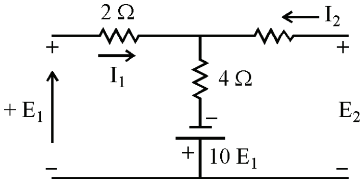
In the given network, \(Z_{11}\) is equal to
What does the term "cut-set" refer to in network analysis ?
Norton's equivalent current is in parallel with :
Norton's equivalent current source is connected in :
Find the value of \(V_{TH}\) using the Thevenin's theorem of the following circuit :

Identify the matrix form for the equation RiL + L \(\frac{di_{L}}{dt}\) + Vc = 0 using state variable concept.
A power factor of 1 indicates a :
A network has 10 nodes and 17 branches. The number of different node pair voltages would be :
Image impedances of port 1 and port 2 of symmetrical two-port network is :
The driving point impedance Z(s) of a network has the pole-zero locations as shown in the following figure. If Z(o) = 3, then Z(s) is :

In the given figure, three equal resistors are connected. The equivalent resistance between point A and B is __________.

In parallel resonance, the phase angle between applied voltage and line current is :
A parallel circuit has R = 1kΩ, C= 50µF and L = 10mH. The quality factor at resonance is ________.
A balanced Y-connected load having impedance (32 + j24)Ω is connected to 400V, 3-φ supply. Current drawn from the supply will be _____________.
The form factor of an alternating quantity is given by
A factory draws an apparent power of 300kVA at lagging power factor of 0.65. The active power drawn by the factory is:
A 50 kW single-phase motor is supplied by an AC source of 50 Hz. If the terminal voltage of the motor is 230 V angle(\(0^\circ\)), the power factor of the motor is 0.5 lag, find the source current.
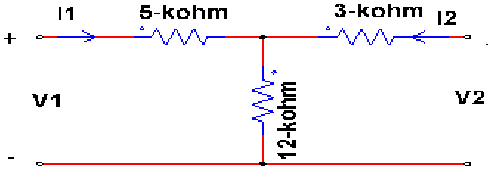
Determine the value of \(Z_{11}\) parameter of the given two port network.
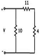
For the given circuit, if all the resistance values are in ohms and the source voltage V = 30 V, then find the source current.
Total number of questions : 20
Number of answered questions : 0
Number of unanswered questions : 20
Network Analysis [ Question No: 1 To 20 ] :
A network is said to be linear if and only if
I. Response is proportional to excitation function
II. Principle of superposition applies
III. Principle of homogeneity applies
IV. It is reciprocal
Your Answer : (Not Answered)
Correct Answer : B
A network is linear if and only if the principles of superposition and homogeneity apply, so option (B) is right. Superposition means that the response to a sum of inputs is the sum of the individual responses, and homogeneity means that scaling the input scales the response by the same factor. Together they define linearity. Statement I, that the response is proportional to the excitation, is only the homogeneity part, so it is incomplete on its own, and the key does not take it. Statement IV, reciprocity, is a different property: a network can be linear without being reciprocal, as a circuit with a gyrator or a dependent source shows, so options (C) and (D) are wrong.
In the given network, \(Z_{11}\) is equal to
Your Answer : (Not Answered)
Correct Answer : B
The input impedance with the output open (\(I_2 = 0\)) is \(Z_{11} = E_1/I_1\), which is \(\frac{6}{11}\) ohm (option B). With the output open, the loop holds the 2 ohm and 4 ohm resistors and the dependent source, whose plus terminal is at the bottom.
\[ E_1 - 2I_1 - 4I_1 + 10E_1 = 0 \]
\[ 11E_1 = 6I_1 \]
\[ Z_{11} = \frac{6}{11}\ \Omega \]
The value \(-\frac{6}{11}\) (A) comes from taking the source with the opposite polarity, which would give \(1 - 10 = -9\) in the denominator, not 11. The other two values do not follow from the loop.
What does the term "cut-set" refer to in network analysis ?
Your Answer : (Not Answered)
Correct Answer : D
A cut-set is a set of branches that, if cut, will divide the network into two parts.
In network topology, a cut-set is a minimal set of branches whose removal separates the graph into exactly two connected parts; removing any fewer branches leaves it connected. Each tree branch defines a fundamental cut-set, and Kirchhoff's current law applied to each cut-set gives the independent node-type equations of the network.
A cut-set is defined by the graph, not by the type of element in the branches, so it is not a set of parallel or series resistors or a combination of resistors and capacitors.
Norton's equivalent current is in parallel with :
Your Answer : (Not Answered)
Correct Answer : A
The Norton current source is in parallel with a resistor.
The Norton equivalent of a linear network is a current source \(I_{N}\), equal to the short-circuit current at the terminals, in parallel with the Norton resistance \(R_{N}\), the resistance seen at the terminals with all independent sources turned off. \(R_{N}\) is the same as the Thevenin resistance. For AC networks it becomes an impedance, but in the standard statement it is a resistance.
A capacitor or an inductor alone is not the Norton element. A voltage source in series with a resistance is the Thevenin equivalent; putting a voltage source in parallel with the current source would not describe the network at all.
Norton's equivalent current source is connected in :
Your Answer : (Not Answered)
Correct Answer : B
The Norton current source is connected in parallel with the load.
Norton's theorem replaces a linear network, as seen from two terminals, by a current source \(I_{N}\) (the short-circuit current at those terminals) in parallel with a resistance \(R_{N}\) (the resistance seen with sources set to zero). The load is then connected across those same two terminals, so it sits in parallel with both the source and \(R_{N}\), and the source current divides between them.
It is the Thevenin voltage source that appears in series with the load. 'Series with the source' and 'parallel with the source' describe the Norton resistance's relation to the source, not the source's connection to the load.
Find the value of \(V_{TH}\) using the Thevenin's theorem of the following circuit :
Your Answer : (Not Answered)
Correct Answer : B
The key gives \(V_{TH}\) = 8.57 V.
The key takes the 24 Ω resistor as the load across A-B and removes it. The open-circuit voltage at A-B is then the voltage across the 12 Ω resistor, which forms a divider with the 2 Ω series resistor:
\[ \begin{aligned} V_{TH} &= 10 \times \frac{12}{2 + 12} \\ &= \frac{120}{14} \approx 8.57\ \text{V} \end{aligned} \]
If the 24 Ω resistor were left in place, the parallel combination (8 Ω) would give 8 V, which is not an option, so the question must be read with the 24 Ω resistor as the load. None of 7.92 V, 1.71 V or 8.35 V is the open-circuit voltage of this divider.
Identify the matrix form for the equation RiL + L \(\frac{di_{L}}{dt}\) + Vc = 0 using state variable concept.
Your Answer : (Not Answered)
Correct Answer : A
The correct matrix form is the first one, with \(di_{L}/dt\) and \(dV_{c}/dt\) on the left and the matrix with rows (-R/L, -1/L) and (1/C, 0).
Take the inductor current and the capacitor voltage as the state variables. Rearranging the loop equation gives the first state equation, and the capacitor law \(i_{L} = C\, dV_{c}/dt\) gives the second:
\[ \begin{aligned} \frac{di_{L}}{dt} &= -\frac{R}{L} i_{L} - \frac{1}{L} V_{c} \\ \frac{dV_{c}}{dt} &= \frac{1}{C} i_{L} \end{aligned} \]
The second option swaps the order of the derivatives without swapping the matrix rows. The third puts the derivatives on the wrong side, and the fourth swaps the two rows, so each pairs the coefficients with the wrong state.
A power factor of 1 indicates a :
Your Answer : (Not Answered)
Correct Answer : B
A power factor of 1 indicates a purely resistive circuit.
Power factor is cos φ, where φ is the phase angle between voltage and current. It equals 1 when φ = 0, that is, when the voltage and current are in phase and the circuit as a whole behaves as a pure resistance. This happens in a circuit of resistors alone, and also in an RLC circuit at resonance, where the inductive and capacitive reactances cancel, which is why the answer speaks of the circuit rather than a single element.
A purely reactive element or circuit has φ = 90° and a power factor of 0, so those options describe the opposite case.
A network has 10 nodes and 17 branches. The number of different node pair voltages would be :
Your Answer : (Not Answered)
Correct Answer : C
The number of node pair voltages is 45.
A node pair voltage is the voltage between any two nodes, so the count is the number of ways of choosing 2 nodes out of 10:
\[ \binom{10}{2} = \frac{10 \times 9}{2} = 45 \]
The number of branches does not enter this count. It matters for other quantities: the number of independent loops is b - n + 1 = 17 - 10 + 1 = 8, and the number of independent node voltages is n - 1 = 9. Seven is b - n, 17 is the branch count, and 50 does not follow from either figure.
Image impedances of port 1 and port 2 of symmetrical two-port network is :
Your Answer : (Not Answered)
Correct Answer : C
For a symmetrical two-port network the image impedances are equal.
The image impedances ZI1 and ZI2 are the pair of impedances such that terminating each port in its own image impedance makes the impedance seen at the other port equal to its image impedance. They are given by \(Z_{I1} = \sqrt{Z_{oc1}Z_{sc1}}\) and \(Z_{I2} = \sqrt{Z_{oc2}Z_{sc2}}\).
In a symmetrical network the two ports look the same from either side, so the open- and short-circuit impedances at port 1 equal those at port 2, and the two image impedances are equal; the common value is the characteristic impedance. They are not zero or infinite in general, and 'not equal' describes an asymmetrical network.
The driving point impedance Z(s) of a network has the pole-zero locations as shown in the following figure. If Z(o) = 3, then Z(s) is :
Your Answer : (Not Answered)
Correct Answer : B
The impedance is \(Z(s) = \dfrac{2(s+3)}{s^{2}+2s+2}\).
The figure shows poles (crosses) at \(s = -1 \pm j1\), and the mark at \(-3\) on the real axis is the zero. So
\[ \begin{aligned} Z(s) &= \frac{K(s + 3)}{(s + 1 - j)(s + 1 + j)} \\ &= \frac{K(s + 3)}{s^{2} + 2s + 2} \end{aligned} \]
Setting \(s = 0\): \(Z(0) = 3K/2 = 3\), so \(K = 2\).
The denominator \(s^{2} + 2s + 3\) would put the poles at \(-1 \pm j\sqrt{2}\), not \(\pm j1\). The options with \(s - 3\) and \(s^{2} - 2s - \ldots\) place the zero and poles in the right half-plane, which is not what the plot shows.
In the given figure, three equal resistors are connected. The equivalent resistance between point A and B is __________.
Your Answer : (Not Answered)
Correct Answer : C
The equivalent resistance is R/3.
Follow the two connecting wires. One joins A directly to P, so A and P are the same node. The other joins Q directly to B, so Q and B are the same node. Now look at where each resistor's ends fall:
- A to Q: between A and B.
- Q to P: between B and A.
- P to B: between A and B.
All three resistors are connected between the same two nodes, so they are in parallel.
\[ \begin{aligned} \frac{1}{R_{AB}} &= \frac{1}{R} + \frac{1}{R} + \frac{1}{R} \\ &= \frac{3}{R}, \quad R_{AB} = \frac{R}{3} \end{aligned} \]
3R treats the resistors as a plain series chain and ignores the two wires, and 2R/3 and 3R/2 come from treating only part of the network as shorted.
In parallel resonance, the phase angle between applied voltage and line current is :
Your Answer : (Not Answered)
Correct Answer : B
At parallel resonance the phase angle is zero.
In a parallel resonant (tank) circuit the reactive current in the inductive branch is exactly cancelled by the reactive current in the capacitive branch. The line current is then only the small in-phase component that supplies the losses, so it is in phase with the applied voltage, the power factor is unity and the circuit's impedance is a maximum and purely resistive.
A phase angle of 90° belongs to a purely inductive or capacitive circuit, 45° to a circuit whose resistance equals its net reactance, and 180° does not arise in a passive circuit.
A parallel circuit has R = 1kΩ, C= 50µF and L = 10mH. The quality factor at resonance is ________.
Your Answer : (Not Answered)
Correct Answer : C
The quality factor is about 70.70.
For a parallel resonant circuit with resistance R in parallel with L and C, the quality factor is \(Q = R\sqrt{C/L}\).
\[ \begin{aligned} Q &= 1000\sqrt{\frac{50 \times 10^{-6}}{10 \times 10^{-3}}} \\ &= 1000 \times \sqrt{5 \times 10^{-3}} \\ &= 1000 \times 0.0707 = 70.7 \end{aligned} \]
Using the series formula \(\frac{1}{R}\sqrt{L/C}\) would give a tiny value, and 100, 90.86 and 78.76 do not follow from these component values.
A balanced Y-connected load having impedance (32 + j24)Ω is connected to 400V, 3-φ supply. Current drawn from the supply will be _____________.
Your Answer : (Not Answered)
Correct Answer : D
The current drawn is 5.77 A.
In a star connection the line current equals the phase current, and each phase sees the phase voltage, the line voltage divided by \(\sqrt{3}\).
\[ \begin{aligned} V_{ph} &= \frac{400}{\sqrt{3}} \approx 230.9\ \text{V} \\ |Z| &= \sqrt{32^{2} + 24^{2}} = 40\ \Omega \\ I &= \frac{230.9}{40} \approx 5.77\ \text{A} \end{aligned} \]
10 A uses the full line voltage across one phase, which is correct only for a delta load's phase current, and 17.32 A is the line current that delta load would draw. 20.50 A does not come from these values.
The form factor of an alternating quantity is given by
Your Answer : (Not Answered)
Correct Answer : C
The form factor is rms value / average value.
Form factor describes the shape of a waveform as the ratio of its rms value to its average (half-cycle mean) value. For a sine wave it is 0.707Vm / 0.637Vm = 1.11, which is why average-responding meters are scaled by 1.11 to read rms.
Maximum value divided by rms value is the peak (crest) factor, 1.414 for a sine wave. The ratios with average or rms value over maximum value, and average over rms, are not the form factor.
A factory draws an apparent power of 300kVA at lagging power factor of 0.65. The active power drawn by the factory is:
Your Answer : (Not Answered)
Correct Answer : D
The active power is 195 kW.
Active power is apparent power multiplied by the power factor.
\[ P = 300 \times 0.65 = 195\ \text{kW} \]
228 kW is the reactive power, \(300 \sin\phi = 300 \times 0.76\), given in kVAR rather than kW, and 285 and 185 kW correspond to no standard calculation from these figures.
A 50 kW single-phase motor is supplied by an AC source of 50 Hz. If the terminal voltage of the motor is 230 V angle(\(0^\circ\)), the power factor of the motor is 0.5 lag, find the source current.
Your Answer : (Not Answered)
Correct Answer : C
For a single phase load the real power is \(P = VI\cos\phi\), so the line current is
\[ \begin{aligned} I = \frac{P}{V\cos\phi} \\ &= \frac{50 \times 10^3}{230 \times 0.5} \\ &= \frac{50000}{115} = 434.8\ \text{A} \end{aligned} \]
This is the value of 434.7 A in the options, option C. A current of 43.47 A or 4.34 A would be a slip of one or two powers of ten, and 0.4347 A would come from taking the power as 50 W. The current lags the voltage by \(\cos^{-1}0.5 = 60^\circ\).
Determine the value of \(Z_{11}\) parameter of the given two port network.
Your Answer : (Not Answered)
Correct Answer : B
The z-parameter \(Z_{11} = V_1 / I_1\) with the output port open circuited (\(I_2 = 0\)).
With port 2 open, no current flows in the 3 kilohm resistor, so the input sees the 5 kilohm resistor in series with the 12 kilohm shunt resistor.
\[ Z_{11} = 5 + 12 = 17\ \text{k}\Omega \]
The 3 kilohm resistor does not enter because it carries no current. The value 15 kilohm adds the 12 and 3 and leaves out the 5, 16 kilohm and 12 kilohm do not match any combination of the series arms with the shunt. The answer is 17 kilohm, option B.
For the given circuit, if all the resistance values are in ohms and the source voltage V = 30 V, then find the source current.
Your Answer : (Not Answered)
Correct Answer : A
The 10 ohm resistor is directly across the 30 V source. The other branch is the 11 ohm resistor in series with the 4 ohm resistor, which is 15 ohms, also directly across the source.
\[ \begin{aligned} I_{10} = \frac{30}{10} \\ &= 3\ \text{A},\qquad I_{15} = \frac{30}{15} \\ &= 2\ \text{A} \end{aligned} \]
\[ I_{source} = 3 + 2 = 5\ \text{A} \]
Equivalently the parallel combination of 10 and 15 ohms is 6 ohms and 30/6 = 5 A. The values 6 A, 10 A and 12 A come from ignoring the series resistor or adding the wrong branches. The answer is 5 A, option A.
Marks
Total number of questions : 20
Number of answered questions : 0
Number of unanswered questions : 20