
Instruction
- Total number of questions : 20
- Time allotted : 30:00 Minutes:Seconds.
- Each question carry 1 mark, no negative marks.
- DO NOT refresh the page.
- All the best
Power Electronics [ Question No: 1 To 20 ] :
A dc to dc transistor chopper supplied from a fixed voltage dc source feeds afixed-resistive-inductive load and a free-wheeling diode. The chopper operates at 1 kHz and 50% duty cycle. Without changing the value of the average dc current through the load, if it is desired to reduce the ripple content of load current, the control action needed will :
Consider the following statements :
The diodes in a voltage source inverter (McMurray Inverter) should be able to :
(1) Withstand a large voltage in the reverse direction
(2) Carry the commutating current excess of load current
(3) Provide the required reverse-bias to the outgoing thyristor
(4) Feedback the reactive current to the source.
Of these statements :
In high voltage SCR based applications Gate control circuit of SCR prefer fibre optical cable for triggering purpose, because :
At high frequency operation of SCR :
Match the following :
| Set I | Set II |
|---|---|
| (a) Phase controlled converter | (i) DC to DC conversion |
| (b) Chopper | (ii) DC to AC conversion |
| (c) Inverter | (iii) AC to AC conversion |
| (d) Dimmerstat | (iv) AC to DC conversion |
The advantage of on-line UPS over off-line UPS is that :
Bridge rectifier is an alternative to :
Field breakdown voltage for silicon used in power devices is :
When checking a good SCR with an ohmmeter it will :
For the following DIAC triggered circuit the pattern of the current trigger pulses at gate (IG) will be :

For an SCR with turn-on time of 5μs, an ideal trigger pulse should have :
An SCR is rated for 650 V PIV. What is the voltage up to which the device can be operated if the voltage safety factor is 2 ?
Which of the following is the symbol of zener diode?
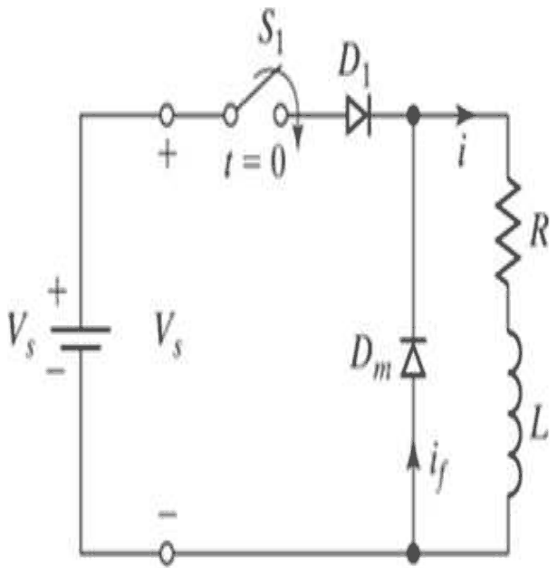
In the given figure, the value of \(R = 0\), the source voltage \(V_s = 300\) V (constant) and the load inductance \(L = 300\ \mu\)H. If the switch S1 is closed till time \(t = 100\ \mu\)s, what is the value of load current I at time \(t = 100\ \mu\)s?
A single-phase voltage source full bridge inverter is connected with 220 V DC. What is the RMS output voltage?
Which of the following devices CANNOT be used as the switching device in voltage source inverters?
A 3-phase half-wave rectifier is supplied with a 440 V, 60 Hz supply. Find the output ripple frequency.
For a 3-phase semi-converter, if the firing angle is \(80^\circ\), then the free-wheeling diode conducts for ______.
How many SCRs are required in single-phase half-wave controlled rectifier?
The average DC output of a single-phase, half-wave controlled rectifier will be maximum if the firing angle is ______.
Total number of questions : 20
Number of answered questions : 0
Number of unanswered questions : 20
Power Electronics [ Question No: 1 To 20 ] :
A dc to dc transistor chopper supplied from a fixed voltage dc source feeds afixed-resistive-inductive load and a free-wheeling diode. The chopper operates at 1 kHz and 50% duty cycle. Without changing the value of the average dc current through the load, if it is desired to reduce the ripple content of load current, the control action needed will :
Your Answer : (Not Answered)
Correct Answer : B
The control action is to increase the chopper frequency keeping the duty cycle constant.
The average load voltage of a chopper is \(D \times V_{s}\), so the average load current is fixed by the duty cycle D. The peak-to-peak ripple in an RL load current is inversely related to the switching frequency relative to the load time constant: at a higher frequency the current has less time to rise and fall in each period, so the ripple shrinks.
Changing the duty cycle, alone or together with frequency, changes the average voltage and hence the average current, which the question forbids. Decreasing the frequency would increase the ripple, the opposite of what is wanted.
Consider the following statements :
The diodes in a voltage source inverter (McMurray Inverter) should be able to :
(1) Withstand a large voltage in the reverse direction
(2) Carry the commutating current excess of load current
(3) Provide the required reverse-bias to the outgoing thyristor
(4) Feedback the reactive current to the source.
Of these statements :
Your Answer : (Not Answered)
Correct Answer : C
Statements (2), (3) and (4) are correct, so the answer is (2), (3) and (4) are correct.
In the McMurray inverter each thyristor has a diode in inverse parallel. During commutation the LC circuit drives a current pulse larger than the load current through the outgoing thyristor; the excess flows through its antiparallel diode (2). The forward drop of that conducting diode is what reverse biases the outgoing thyristor so that it can turn off (3). With an inductive load the same diodes return the reactive (load) current to the DC source (4).
Statement (1) is wrong: because each diode is connected in antiparallel with a thyristor, the reverse voltage across it can never exceed the thyristor's on-state drop, so it never has to withstand a large reverse voltage. That rules out every option containing (1).
In high voltage SCR based applications Gate control circuit of SCR prefer fibre optical cable for triggering purpose, because :
Your Answer : (Not Answered)
Correct Answer : C
Fibre optic triggering is preferred because it provides a very high level of insulation/isolation.
In high voltage applications such as HVDC valves, SCRs sit at potentials of many kilovolts above ground, while the gate control electronics are near ground. An optical fibre carries the trigger pulse as light, and since glass does not conduct, it isolates the control circuit completely from the high voltage. It is also immune to electromagnetic interference.
An optical fibre carries a signal, not power, so it does not provide low impedance, gain or high current for the power circuit.
At high frequency operation of SCR :
Your Answer : (Not Answered)
Correct Answer : D
At high frequency, switching losses become significant.
Every time an SCR turns on or off, there is a short interval during which both the voltage across it and the current through it are appreciable, and energy is dissipated. The average switching loss is that energy multiplied by the switching frequency:
\[ P_{sw} = (E_{on} + E_{off}) \times f \]
so it grows in proportion to frequency and limits SCRs to relatively low frequencies. di/dt and dv/dt ratings must always be respected, and reverse blocking voltage is set by the circuit voltage; none of these grows with operating frequency in the way switching loss does.
Match the following :
| Set I | Set II |
|---|---|
| (a) Phase controlled converter | (i) DC to DC conversion |
| (b) Chopper | (ii) DC to AC conversion |
| (c) Inverter | (iii) AC to AC conversion |
| (d) Dimmerstat | (iv) AC to DC conversion |
Your Answer : (Not Answered)
Correct Answer : B
The correct code is (a)-(iv), (b)-(i), (c)-(ii), (d)-(iii).
A phase-controlled converter (controlled rectifier) turns AC into variable DC (iv). A chopper switches a DC supply on and off rapidly to give a different average DC voltage (i). An inverter produces AC from DC (ii). A dimmerstat, a variable autotransformer, changes the magnitude of an AC voltage, AC to AC (iii).
The other codes give the chopper an AC role or treat the dimmerstat as a DC device, which does not fit how these circuits work.
The advantage of on-line UPS over off-line UPS is that :
Your Answer : (Not Answered)
Correct Answer : B
The advantage of an on-line UPS is that there is no phase change or break in the output when the mains fails.
An on-line (double-conversion) UPS rectifies the mains into the battery and DC bus and always feeds the load from its inverter. When the mains fails nothing needs to switch, so the load sees no interruption or jump in phase. An off-line UPS feeds the load from the mains and switches to the inverter after it detects the failure, which takes a few milliseconds.
A true sine wave (A) depends on how the inverter is built; the topology does not fix it, so it is not the defining advantage. Power and backup time (C) are set by the inverter rating and battery bank, not by whether the UPS is on-line. Conversion efficiency (D) is actually lower in an on-line UPS, because all the power is converted twice.
Bridge rectifier is an alternative to :
Your Answer : (Not Answered)
Correct Answer : A
The bridge rectifier is an alternative to the full wave rectifier.
Both the bridge rectifier and the centre-tapped full wave rectifier conduct on both half cycles. The bridge uses four diodes but needs no centre-tapped transformer, and each diode has to withstand only the peak voltage rather than twice the peak, so it is widely used in place of the centre-tapped circuit.
A half wave rectifier uses only one half cycle, so the bridge is an improvement on it rather than an alternative. A voltage regulator and a π-section filter come after the rectifier in a power supply and do a different job.
Field breakdown voltage for silicon used in power devices is :
Your Answer : (Not Answered)
Correct Answer : B
The breakdown field of silicon is about 300 kV/cm.
The critical electric field for avalanche breakdown in silicon is about \(3 \times 10^{5}\) V/cm, depending somewhat on doping. This figure sets how thick the drift region of a power device must be for a given blocking voltage, and is why high-voltage silicon devices need wide, lightly doped regions.
100 kV/cm is too low. Around 1 MV/cm is not silicon's figure, and about 10 MV/cm is the breakdown field of SiO2, the insulator, not of silicon.
When checking a good SCR with an ohmmeter it will :
Your Answer : (Not Answered)
Correct Answer : C
A good SCR will show high resistance in both directions.
Between anode and cathode an SCR is a four-layer PNPN device with three junctions. Whichever way the ohmmeter is connected, at least one junction is reverse biased, and without a gate trigger the SCR stays off, so the meter reads a high resistance both ways.
Low resistance in one or both directions would indicate a shorted device. Behaviour like a diode, low one way and high the other, would also mean the SCR is faulty.
For the following DIAC triggered circuit the pattern of the current trigger pulses at gate (IG) will be :
Your Answer : (Not Answered)
Correct Answer : C
The gate current is a train of sharp pulses that decay exponentially, alternating in sign, waveform (C).
In this circuit the resistor R charges the capacitor C from the AC supply. When the capacitor voltage reaches the breakover voltage of the DIAC, the DIAC suddenly conducts and the capacitor discharges through it into the gate of the triac. The gate current therefore jumps up almost instantly and then falls as the capacitor discharges through the gate resistance, which is an exponential decay. The same thing happens on the negative half-cycle with the opposite sign, because the DIAC is symmetrical.
Waveform (A) is just the sine wave of the supply, with no triggering action. Waveform (B) is a smoothly rising curve with no sudden jump, which a breakover device cannot give. Waveform (D) shows a sudden rise but then a rounded fall that does not look like a capacitor discharge; C is the standard shape.
For an SCR with turn-on time of 5μs, an ideal trigger pulse should have :
Your Answer : (Not Answered)
Correct Answer : C
The ideal pulse has a short rise time with pulse width = 6 μs.
The gate pulse must last longer than the SCR's turn-on time, so that the anode current has risen above the latching current before the gate drive is removed; otherwise the SCR turns off again when the pulse ends. With a turn-on time of 5 μs, a 6 μs pulse is long enough while a 3 μs pulse is not.
A short (fast) rise time makes turn-on quick and spreads conduction across the junction rapidly, reducing local heating and di/dt stress. A long rise time slows turn-on, so both 'long rise time' options are worse.
An SCR is rated for 650 V PIV. What is the voltage up to which the device can be operated if the voltage safety factor is 2 ?
Your Answer : (Not Answered)
Correct Answer : A
The device can be operated up to about 230 V.
The voltage safety factor is the ratio of the PIV rating to the peak working voltage. With a factor of 2, the peak working voltage is half the rating, and for a sinusoidal supply the rms value is the peak divided by \(\sqrt{2}\).
\[ \begin{aligned} V_{m} &= \frac{650}{2} = 325\ \text{V} \\ V_{rms} &= \frac{325}{\sqrt{2}} \approx 229.8 \approx 230\ \text{V} \end{aligned} \]
325 V is the permissible peak, not the supply voltage rating, and 459 V is \(650/\sqrt{2}\), which ignores the safety factor. 650 V would leave no margin at all.
Which of the following is the symbol of zener diode?
Your Answer : (Not Answered)
Correct Answer : C
The symbol of a zener diode is the one with the bent bar at the cathode, shown as (C). In the symbol, the triangle shows the direction of forward current and the bar at the cathode has its ends turned in the shape of a Z to show the breakdown action.
Symbol (A) is a light-emitting diode with arrows leaving the diode, (B) is a photodiode with arrows going towards it, and (D) is an ordinary junction diode with a straight bar. So the third option is the answer.
In the given figure, the value of \(R = 0\), the source voltage \(V_s = 300\) V (constant) and the load inductance \(L = 300\ \mu\)H. If the switch S1 is closed till time \(t = 100\ \mu\)s, what is the value of load current I at time \(t = 100\ \mu\)s?
Your Answer : (Not Answered)
Correct Answer : C
With \(R = 0\) the load is a pure inductance, and when the switch S1 closes at \(t = 0\) the constant source voltage \(V_s\) is applied across \(L\) (the diode \(D_1\) conducts, and \(D_m\) is reverse biased). The current rises linearly.
\[ V_s = L\frac{di}{dt} \Rightarrow i(t) = \frac{V_s}{L}t \]
\[ \begin{aligned} i(100\ \mu\text{s}) \\ &= \frac{300}{300 \times 10^{-6}} \times 100 \times 10^{-6} \\ &= 100\ \text{A} \end{aligned} \]
The answer is 100 A, option C. The value of 50 A would be at \(t = 50\ \mu\)s and 200 A at \(t = 200\ \mu\)s.
A single-phase voltage source full bridge inverter is connected with 220 V DC. What is the RMS output voltage?
Your Answer : (Not Answered)
Correct Answer : A
The output of a single phase full bridge inverter with a DC input \(V_{dc}\) is a square wave that alternates between \(+V_{dc}\) and \(-V_{dc}\). The square of this wave is constant, \(V_{dc}^2\), so the RMS output voltage is
\[ \begin{aligned} V_{rms} = \sqrt{\frac{1}{T}\int_0^T v^2\,dt} \\ &= V_{dc} = 220\ \text{V} \end{aligned} \]
A half bridge inverter would give \(V_{dc}/2 = 110\) V, which is the other value in the list, and 100 V and \(200/\sqrt{2}\) V have no basis in the data. The answer is 220 V, option A.
Which of the following devices CANNOT be used as the switching device in voltage source inverters?
Your Answer : (Not Answered)
Correct Answer : D
A voltage source inverter needs switches that can be turned on and off under control: SCRs with forced commutation circuits, GTOs, power transistors, MOSFETs and IGBTs can all serve as the switching device.
A DIAC is a bidirectional trigger diode with no gate terminal; it breaks over at a fixed voltage and is used to trigger a TRIAC, so it cannot be controlled as a switching device in an inverter. The answer is DIAC, option D.
A 3-phase half-wave rectifier is supplied with a 440 V, 60 Hz supply. Find the output ripple frequency.
Your Answer : (Not Answered)
Correct Answer : D
The output ripple frequency is 180 Hz. In a 3-phase half wave rectifier there are three pulses in each cycle of the supply, so the ripple frequency is three times the supply frequency.
\[ f_{ripple} = 3 \times 60 = 180\ \text{Hz} \]
The value 60 Hz would be the ripple of a single phase half wave circuit, 120 Hz would be that of a single phase full wave circuit, and 30 Hz is not a ripple frequency of any such circuit at 60 Hz. The voltage of 440 V does not change the ripple frequency. So the fourth option is the answer.
For a 3-phase semi-converter, if the firing angle is \(80^\circ\), then the free-wheeling diode conducts for ______.
Your Answer : (Not Answered)
Correct Answer : D
In a three phase semi-converter, each SCR carries current for 120 degrees at most, and the free wheeling diode starts to conduct when the output voltage tries to go negative, which happens only for firing angles above \(60^\circ\). For \(\alpha > 60^\circ\) the diode conducts for \(\alpha - 60^\circ\) in each of the three intervals of the supply cycle.
\[ \alpha - 60^\circ = 80^\circ - 60^\circ = 20^\circ \]
The conduction of the diode is zero for \(\alpha \le 60^\circ\), so 60 degrees and 90 degrees cannot be the answers, and 40 degrees would correspond to \(\alpha = 100^\circ\). The answer is \(20^\circ\), option D.
How many SCRs are required in single-phase half-wave controlled rectifier?
Your Answer : (Not Answered)
Correct Answer : B
One SCR is needed in a single phase half wave controlled rectifier. The thyristor conducts in the positive half cycle, after it is triggered at the firing angle, and blocks in the negative half cycle, so the one device controls the output.
Zero would be an uncontrolled circuit with a diode. Two SCRs would be used in a full wave controlled rectifier with a centre tap or in a half controlled bridge, and four would be used in a full controlled bridge. So the second option is the answer.
The average DC output of a single-phase, half-wave controlled rectifier will be maximum if the firing angle is ______.
Your Answer : (Not Answered)
Correct Answer : A
For a single phase half wave controlled rectifier with a resistive load the average output voltage is
\[ V_{dc} = \frac{V_m}{2\pi}(1 + \cos\alpha) \]
This is greatest when \(\cos\alpha\) is greatest, that is at \(\alpha = 0^\circ\), where \(V_{dc} = V_m/\pi\), the value of an uncontrolled rectifier. As the firing angle increases, \(V_{dc}\) falls, to \(V_m/(2\pi)\) at 90 degrees and to zero at 180 degrees. The answer is \(0^\circ\), option A.
Marks
Total number of questions : 20
Number of answered questions : 0
Number of unanswered questions : 20