
GATE EE 2013: Electrical Engineering
Text of page 1
SESSION - 1
Text of page 2
2013                                                                      Question Booklet Code
                                                                                                         A
                               EE : ELECTRICAL ENGINEERING
Duration: Three Hours                                                                     Maximum Marks: 100

Read the following instructions carefully.

    1. Do not open the seal of the Question Booklet until you are asked to do so by the invigilator.
    2. Take out the Optical Response Sheet (ORS) from this Question Booklet without breaking the seal
        and read the instructions printed on the ORS carefully. If you find that either:
        a. The Question Booklet Code printed at the right hand top corner of this page does not match with
             the Question Booklet Code at the right hand top corner of the ORS or
        b. The Question Paper Code preceding the Registration number on the ORS is not EE,
       then exchange the booklet immediately with a new sealed Question Booklet.
    3. On the right half hand side of the ORS, using ONLY a black ink ballpoint pen, (i) darken the
       appropriate bubble under each digit of your registration number and (ii) write your registration number,
       your name and name of the examination centre and put your signature at the specified location.
    4. This Question Booklet contains 20 pages including blank pages for rough work. After you are
       permitted to open the seal, check all pages and report discrepancies, if any, to the invigilator.
    5. There are a total of 65 questions carrying 100 marks. All these questions are of objective type. Each
       question has only one correct answer. Questions must be answered on the left hand side of the ORS
       by darkening the appropriate bubble (marked A, B, C, D) using ONLY a black ink ballpoint pen
       against the question number. For each question darken the bubble of the correct answer. More
       than one answer bubbled against a question will be treated as an incorrect response.
    6. Since bubbles darkened by the black ink ballpoint pen cannot be erased, candidates should darken the
       bubbles in the ORS very carefully.
    7. Questions Q.1 – Q.25 carry 1 mark each. Questions Q.26 – Q.55 carry 2 marks each. The 2 marks
       questions include two pairs of common data questions and two pairs of linked answer questions. The
       answer to the second question of the linked answer questions depends on the answer to the first
       question of the pair. If the first question in the linked pair is wrongly answered or is not attempted,
       then the answer to the second question in the pair will not be evaluated.
    8. Questions Q.56 – Q.65 belong to General Aptitude (GA) section and carry a total of 15 marks.
       Questions Q.56 – Q.60 carry 1 mark each, and questions Q.61 – Q.65 carry 2 marks each.
    9. Questions not attempted will result in zero mark and wrong answers will result in NEGATIVE
       marks. For all 1 mark questions, ⅓ mark will be deducted for each wrong answer. For all 2 marks
       questions, ⅔ mark will be deducted for each wrong answer. However, in the case of the linked
       answer question pair, there will be negative marks only for wrong answer to the first question and no
       negative marks for wrong answer to the second question.
    10. Calculator is allowed whereas charts, graph sheets or tables are NOT allowed in the examination hall.
    11. Rough work can be done on the Question Booklet itself. Blank pages are provided at the end of the
        Question Booklet for rough work.
    12. Before the start of the examination, write your name and registration number in the space provided
        below using a black ink ballpoint pen.

           Name

           Registration Number         EE

EE-A                                                                                                       1/20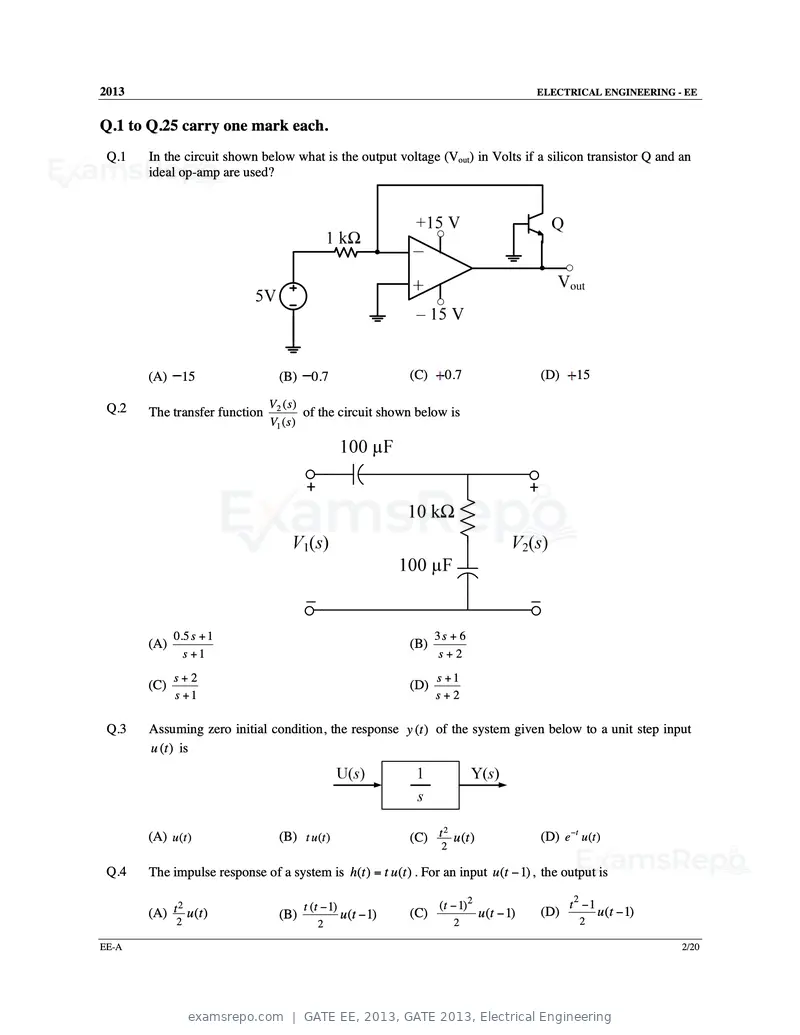
Text of page 3
2013                                                                                         ELECTRICAL ENGINEERING - EE


Q.1 to Q.25 carry one mark each.
 Q.1   In the circuit shown below what is the output voltage (Vout) in Volts if a silicon transistor Q and an
       ideal op-amp are used?


       (A)    15                 (B)     0.7                   (C)     0.7                   (D)     15

 Q.2                           V2 ( s )
       The transfer function            of the circuit shown below is
                               V1 ( s )


             0.5 s + 1                                               3s + 6
       (A)                                                     (B)
               s +1                                                   s+2
             s+2                                                     s +1
       (C)                                                     (D)
             s +1                                                    s+2

 Q.3   Assuming zero initial condition, the response y (t ) of the system given below to a unit step input
       u (t ) is


                                                                                             (D) e −t u (t )
                                                                    2
       (A) u (t )                (B) t u (t )                  (C) t u (t )
                                                                      2

 Q.4   The impulse response of a system is h(t ) = t u (t ) . For an input u (t − 1) , the output is

             2                         t (t − 1)                     (t − 1) 2                      t2 −1
       (A) t u (t )              (B)               u (t − 1)   (C)               u (t − 1)   (D)            u (t − 1)
             2                            2                               2                           2

EE-A                                                                                                                    2/20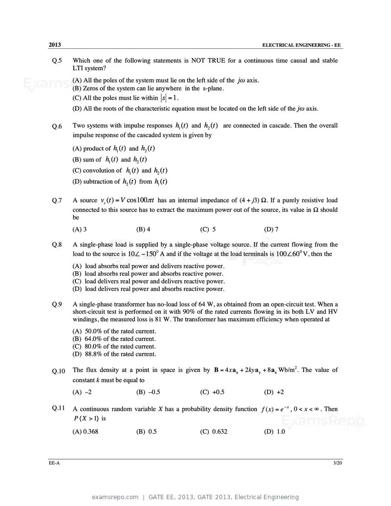
Text of page 4
2013                                                                                ELECTRICAL ENGINEERING - EE


 Q.5    Which one of the following statements is NOT TRUE for a continuous time causal and stable
        LTI system?
        (A) All the poles of the system must lie on the left side of the jω axis.
        (B) Zeros of the system can lie anywhere in the s-plane.
        (C) All the poles must lie within s = 1.
        (D) All the roots of the characteristic equation must be located on the left side of the jω axis.

 Q.6    Two systems with impulse responses h1 (t ) and h2 (t ) are connected in cascade. Then the overall
        impulse response of the cascaded system is given by

        (A) product of h1 (t ) and h2 (t )
        (B) sum of h1 (t ) and h2 (t )
        (C) convolution of h1 (t ) and h2 (t )
        (D) subtraction of h2 (t ) from h1 (t )

 Q.7    A source vs (t ) = V cos100π t has an internal impedance of (4 + j3) Ω. If a purely resistive load
        connected to this source has to extract the maximum power out of the source, its value in Ω should
        be
        (A) 3                     (B) 4                   (C) 5                     (D) 7

 Q.8    A single-phase load is supplied by a single-phase voltage source. If the current flowing from the
        load to the source is 10∠ − 1500 A and if the voltage at the load terminals is 100∠600 V, then the
        (A) load absorbs real power and delivers reactive power.
        (B) load absorbs real power and absorbs reactive power.
        (C) load delivers real power and delivers reactive power.
        (D) load delivers real power and absorbs reactive power.

 Q.9    A single-phase transformer has no-load loss of 64 W, as obtained from an open-circuit test. When a
        short-circuit test is performed on it with 90% of the rated currents flowing in its both LV and HV
        windings, the measured loss is 81 W. The transformer has maximum efficiency when operated at
        (A) 50.0% of the rated current.
        (B) 64.0% of the rated current.
        (C) 80.0% of the rated current.
        (D) 88.8% of the rated current.

 Q.10   The flux density at a point in space is given by B = 4 x a x + 2ky a y + 8 a z Wb/m2. The value of
        constant k must be equal to
        (A) –2                    (B) –0.5                (C) +0.5                  (D) +2

 Q.11   A continuous random variable X has a probability density function f ( x) = e − x , 0 < x < ∞ . Then
        P { X > 1} is

        (A) 0.368                 (B) 0.5                 (C) 0.632                 (D) 1.0


EE-A                                                                                                        3/20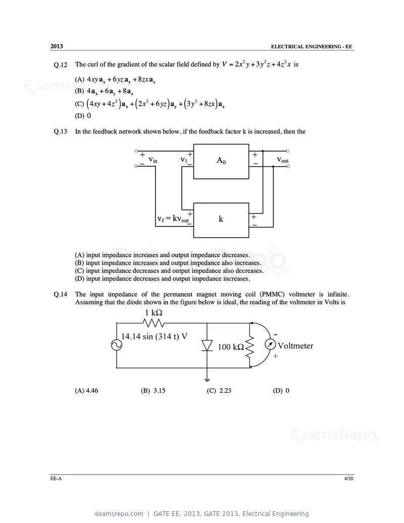
Text of page 5
2013                                                                                  ELECTRICAL ENGINEERING - EE


 Q.12   The curl of the gradient of the scalar field defined by V = 2 x 2 y + 3 y 2 z + 4 z 2 x is

        (A) 4 xy a x + 6 yz a y + 8 zx a z
        (B) 4 a x + 6 a y + 8 a z

             (            )         (                 )    (
        (C) 4 xy + 4 z 2 a x + 2 x 2 + 6 yz a y + 3 y 2 + 8 zx a z   )
        (D) 0

 Q.13   In the feedback network shown below, if the feedback factor k is increased, then the


                                        + v                    +               +         vout
                                              in          v1          A0        –
                                        –                      –


                                                   vf = kvout+           k     +
                                                               –               –


        (A) input impedance increases and output impedance decreases.
        (B) input impedance increases and output impedance also increases.
        (C) input impedance decreases and output impedance also decreases.
        (D) input impedance decreases and output impedance increases.

 Q.14   The input impedance of the permanent magnet moving coil (PMMC) voltmeter is infinite.
        Assuming that the diode shown in the figure below is ideal, the reading of the voltmeter in Volts is


        (A) 4.46                        (B) 3.15                   (C) 2.23            (D) 0


EE-A                                                                                                          4/20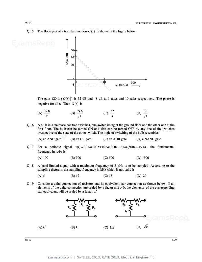
Text of page 6
2013                                                                            ELECTRICAL ENGINEERING - EE


 Q.15   The Bode plot of a transfer function G (s ) is shown in the figure below.


                            Gain (dB)


        The gain (20 log G ( s ) ) is 32 dB and –8 dB at 1 rad/s and 10 rad/s respectively. The phase is
        negative for all ω. Then G (s) is

              39.8                            39.8                  32                    32
        (A)                             (B)                   (C)                   (D)
               s                                s2                   s                    s2

 Q.16   A bulb in a staircase has two switches, one switch being at the ground floor and the other one at the
        first floor. The bulb can be turned ON and also can be turned OFF by any one of the switches
        irrespective of the state of the other switch. The logic of switching of the bulb resembles
        (A) an AND gate                 (B) an OR gate        (C) an XOR gate       (D) a NAND gate

 Q.17   For a periodic signal v(t ) = 30 sin 100 t + 10 cos 300 t + 6 sin (500 t + π / 4) , the fundamental
        frequency in rad/s is
        (A) 100                         (B) 300               (C) 500               (D) 1500

 Q.18   A band-limited signal with a maximum frequency of 5 kHz is to be sampled. According to the
        sampling theorem, the sampling frequency in kHz which is not valid is
        (A) 5                           (B) 12                (C) 15                (D) 20

 Q.19   Consider a delta connection of resistors and its equivalent star connection as shown below. If all
        elements of the delta connection are scaled by a factor k, k > 0, the elements of the corresponding
        star equivalent will be scaled by a factor of


                                                 Ra                      RC     RB
                                 Rb                      Rc
                                                                           RA


        (A) k2                          (B) k                 (C) 1/k               (D)    k


EE-A                                                                                                       5/20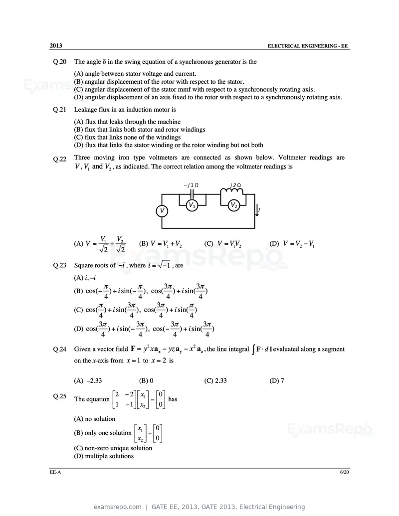
Text of page 7
2013 ELECTRICAL ENGINEERING - EE
Q.20 The angle δ in the swing equation of a synchronous generator is the
(A) angle between stator voltage and current.
(B) angular displacement of the rotor with respect to the stator.
(C) angular displacement of the stator mmf with respect to a synchronously rotating axis.
(D) angular displacement of an axis fixed to the rotor with respect to a synchronously rotating axis.
Q.21 Leakage flux in an induction motor is
(A) flux that leaks through the machine
(B) flux that links both stator and rotor windings
(C) flux that links none of the windings
(D) flux that links the stator winding or the rotor winding but not both
Q.22 Three moving iron type voltmeters are connected as shown below. Voltmeter readings are
V , V1 and V2 , as indicated. The correct relation among the voltmeter readings is
V1 V2
(A) V = + (B) V = V1 + V2 (C) V = VV
1 2 (D) V = V2 − V1
2 2
Q.23 Square roots of −i , where i = −1 , are
(A) i, –i
π π 3π 3π
(B) cos( − ) + i sin( − ), cos( ) + i sin( )
4 4 4 4
π 3π 3π π
(C) cos( ) + i sin( ), cos( ) + i sin( )
4 4 4 4
3π 3π 3π 3π
(D) cos( ) + i sin( − ), cos( − ) + i sin( )
4 4 4 4
Given a vector field F = y x a x − yz a y − x a z , the line integral ∫ F ⋅ d l evaluated along a segment
2 2
Q.24
on the x-axis from x = 1 to x = 2 is
(A) –2.33 (B) 0 (C) 2.33 (D) 7
Q.25 2 − 2 x1 0
The equation = has
1 − 1 x2 0
(A) no solution
x 0
(B) only one solution 1 =
x2 0
(C) non-zero unique solution
(D) multiple solutions
EE-A 6/20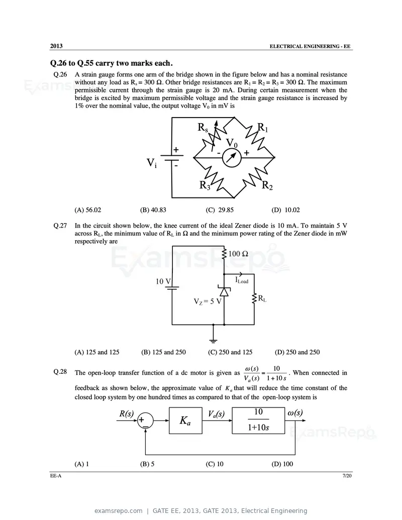
Text of page 8
2013                                                                              ELECTRICAL ENGINEERING - EE


Q.26 to Q.55 carry two marks each.
 Q.26   A strain gauge forms one arm of the bridge shown in the figure below and has a nominal resistance
        without any load as Rs = 300 Ω. Other bridge resistances are R1 = R2 = R3 = 300 Ω. The maximum
        permissible current through the strain gauge is 20 mA. During certain measurement when the
        bridge is excited by maximum permissible voltage and the strain gauge resistance is increased by
        1% over the nominal value, the output voltage V0 in mV is


                                                      Rs                     R1
                                                                 V0
                                             +               ‐         +
                                   Vi        ‐
                                                      R3                      R2

        (A) 56.02                (B) 40.83             (C) 29.85                  (D) 10.02

 Q.27   In the circuit shown below, the knee current of the ideal Zener diode is 10 mA. To maintain 5 V
        across RL, the minimum value of RL in Ω and the minimum power rating of the Zener diode in mW
        respectively are


        (A) 125 and 125          (B) 125 and 250           (C) 250 and 125         (D) 250 and 250

                                                                    ω (s)      10
 Q.28   The open-loop transfer function of a dc motor is given as          =         . When connected in
                                                                    Va ( s) 1 + 10 s
        feedback as shown below, the approximate value of K a that will reduce the time constant of the
        closed loop system by one hundred times as compared to that of the open-loop system is

                          R(s)                         Va(s)                 10        ω(s)
                                 +_              Ka
                                                                        1+10s


        (A) 1                    (B) 5                 (C) 10                     (D) 100
EE-A                                                                                                      7/20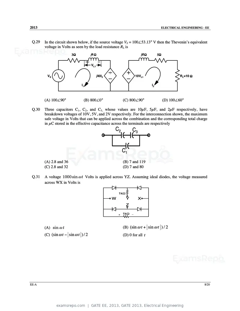
Text of page 9
2013                                                                                   ELECTRICAL ENGINEERING - EE


 Q.29   In the circuit shown below, if the source voltage VS = 100∠53.13° V then the Thevenin’s equivalent
        voltage in Volts as seen by the load resistance RL is
                         3Ω            j4 Ω                               j6 Ω        5Ω


                                       VL1


         VS                                  j40I2                     10VL1                        RL=10 Ω

                                I1                                               I2


        (A) 100∠90°              (B) 800∠0°                  (C) 800∠90°                   (D) 100∠60°

 Q.30   Three capacitors C1, C2, and C3, whose values are 10µF, 5µF, and 2µF respectively, have
        breakdown voltages of 10V, 5V, and 2V respectively. For the interconnection shown, the maximum
        safe voltage in Volts that can be applied across the combination and the corresponding total charge
        in µC stored in the effective capacitance across the terminals are respectively
                                                     C2            C3


                                                             C1
        (A) 2.8 and 36                                       (B) 7 and 119
        (C) 2.8 and 32                                       (D) 7 and 80

 Q.31   A voltage 1000 sin ω t Volts is applied across YZ. Assuming ideal diodes, the voltage measured
        across WX in Volts is

                                                         1kΩ
                                                     W         Y        X
                                                               Z

                                                         +   1kΩ   _


        (A) sin ω t                                          (B) (sin ω t + sin ω t ) / 2
        (C) (sin ω t − sin ω t ) / 2                         (D) 0 for all t


EE-A                                                                                                           8/20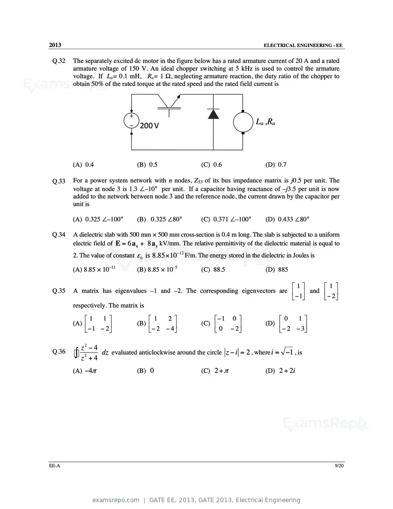
Text of page 10
2013 ELECTRICAL ENGINEERING - EE
Q.32 The separately excited dc motor in the figure below has a rated armature current of 20 A and a rated
armature voltage of 150 V. An ideal chopper switching at 5 kHz is used to control the armature
voltage. If La= 0.1 mH, Ra= 1 Ω, neglecting armature reaction, the duty ratio of the chopper to
obtain 50% of the rated torque at the rated speed and the rated field current is
200 V La ,Ra
(A) 0.4 (B) 0.5 (C) 0.6 (D) 0.7
Q.33 For a power system network with n nodes, Z33 of its bus impedance matrix is j0.5 per unit. The
voltage at node 3 is 1.3 ∠–10° per unit. If a capacitor having reactance of –j3.5 per unit is now
added to the network between node 3 and the reference node, the current drawn by the capacitor per
unit is
(A) 0.325 ∠–100° (B) 0.325 ∠80° (C) 0.371 ∠–100° (D) 0.433 ∠80°
Q.34 A dielectric slab with 500 mm × 500 mm cross-section is 0.4 m long. The slab is subjected to a uniform
electric field of E = 6 a x + 8 a y kV/mm. The relative permittivity of the dielectric material is equal to
2. The value of constant ε 0 is 8.85 × 10⁻¹² F/m. The energy stored in the dielectric in Joules is
(A) 8.85 × 10⁻¹¹ (B) 8.85 × 10⁻⁵ (C) 88.5 (D) 885
1 1
Q.35 A matrix has eigenvalues –1 and –2. The corresponding eigenvectors are and
−1 − 2
respectively. The matrix is
1 1 1 2 − 1 0 0 1
(A) (B) (C) (D)
− 1 − 2 − 2 − 4 0 − 2 − 2 − 3
z2 − 4
Q.36
∫ z 2 + 4 dz evaluated anticlockwise around the circle z − i = 2 , where i = −1 , is
(A) −4π (B) 0 (C) 2 + π (D) 2 + 2i
EE-A 9/20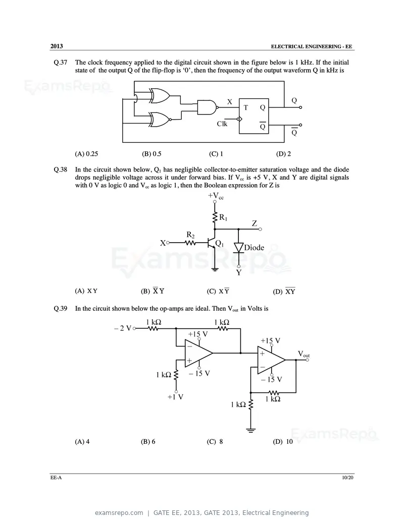
Text of page 11
2013                                                                              ELECTRICAL ENGINEERING - EE


 Q.37   The clock frequency applied to the digital circuit shown in the figure below is 1 kHz. If the initial
        state of the output Q of the flip-flop is ‘0’, then the frequency of the output waveform Q in kHz is


        (A) 0.25                (B) 0.5                  (C) 1                     (D) 2

 Q.38   In the circuit shown below, Q1 has negligible collector-to-emitter saturation voltage and the diode
        drops negligible voltage across it under forward bias. If Vcc is +5 V, X and Y are digital signals
        with 0 V as logic 0 and Vcc as logic 1, then the Boolean expression for Z is


        (A) X Y                 (B) X Y                 (C) X Y                   (D) XY

 Q.39   In the circuit shown below the op-amps are ideal. Then Vout in Volts is


        (A) 4                   (B) 6                   (C) 8                     (D) 10


EE-A                                                                                                      10/20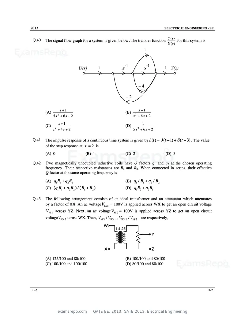
Text of page 12
2013                                                                             ELECTRICAL ENGINEERING - EE


                                                                                   Y (s)
 Q.40   The signal flow graph for a system is given below. The transfer function          for this system is
                                                                                   U ( s)


                       s +1                                         s +1
        (A)                                              (B)
              5s + 6s + 2
                   2
                                                               s + 6s + 2
                                                                2


                   s +1                                                 1
        (C)                                              (D)
              s + 4s + 2
               2
                                                               5s + 6s + 2
                                                                    2


 Q.41   The impulse response of a continuous time system is given by h(t ) = δ (t − 1) + δ (t − 3) . The value
        of the step response at t = 2 is
        (A) 0                     (B) 1                  (C) 2                    (D) 3

 Q.42   Two magnetically uncoupled inductive coils have Q factors q1 and q2 at the chosen operating
        frequency. Their respective resistances are R1 and R2. When connected in series, their effective
        Q factor at the same operating frequency is

        (A) q1 R1 + q2 R2                                (B) q1 / R1 + q2 / R2
        (C) (q1R1 + q2 R2 ) / ( R1 + R2 )                (D) q1R2 + q2 R1

 Q.43   The following arrangement consists of an ideal transformer and an attenuator which attenuates
        by a factor of 0.8. An ac voltage VWX 1 = 100V is applied across WX to get an open circuit voltage
        VYZ 1 across YZ. Next, an ac voltage VYZ 2 = 100V is applied across YZ to get an open circuit
        voltage VWX 2 across WX. Then, VYZ 1 / VWX 1 , VWX 2 / VYZ 2 are respectively,
                                            W
                                                   1:1.25
                                                                            Y


                                            X                               Z

        (A) 125/100 and 80/100                           (B) 100/100 and 80/100
        (C) 100/100 and 100/100                          (D) 80/100 and 80/100


EE-A                                                                                                           11/20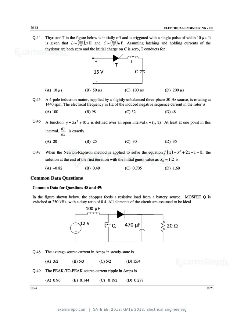
Text of page 13
2013                                                                                ELECTRICAL ENGINEERING - EE


 Q.44   Thyristor T in the figure below is initially off and is triggered with a single pulse of width 10 µs. It
        is given that L = (100π
                                ) µ H and C = (100π )µ F. Assuming latching and holding currents of the
        thyristor are both zero and the initial charge on C is zero, T conducts for


                                        +                      L
                                                      T
                                       15 V                        C
                                        ‐
        (A) 10 µs                  (B) 50 µs               (C) 100 µs                (D) 200 µs

 Q.45   A 4-pole induction motor, supplied by a slightly unbalanced three-phase 50 Hz source, is rotating at
        1440 rpm. The electrical frequency in Hz of the induced negative sequence current in the rotor is
        (A) 100                    (B) 98                  (C) 52                    (D) 48

 Q.46   A function y = 5 x 2 + 10 x is defined over an open interval x = (1, 2) . At least at one point in this
                  dy
        interval,    is exactly
                  dx
        (A) 20                     (B) 25                  (C) 30                    (D) 35

        When the Newton-Raphson method is applied to solve the equation f ( x ) = x + 2 x − 1 = 0, the
                                                                                                 3
 Q.47
        solution at the end of the first iteration with the initial guess value as x0 = 1.2 is

        (A) –0.82                  (B) 0.49                (C) 0.705                 (D) 1.69

Common Data Questions
 Common Data for Questions 48 and 49:

 In the figure shown below, the chopper feeds a resistive load from a battery source. MOSFET Q is
 switched at 250 kHz, with a duty ratio of 0.4. All elements of the circuit are assumed to be ideal.
                                   100 µH


                              12 V                         470 µF
                                                      Q                               20 Ω


 Q.48   The average source current in Amps in steady-state is

        (A) 3/2          (B) 5/3            (C) 5/2         (D) 15/4

 Q.49   The PEAK-TO-PEAK source current ripple in Amps is

        (A) 0.96         (B) 0.144          (C) 0.192       (D) 0.288
EE-A                                                                                                         12/20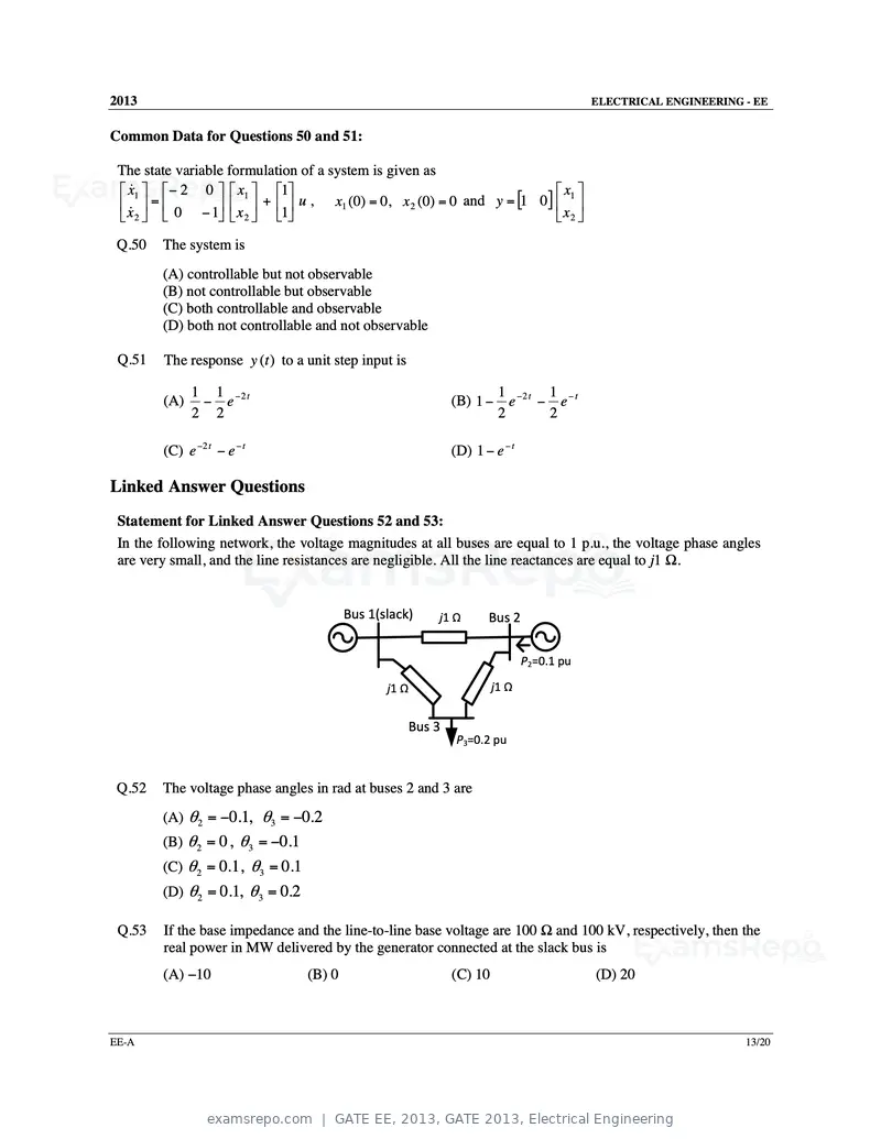
Text of page 14
2013 ELECTRICAL ENGINEERING - EE
Common Data for Questions 50 and 51:
The state variable formulation of a system is given as
x&1 − 2 0 x1 1 x1
x& = 0 − 1 x + 1 u , x1 (0) = 0, x 2 (0) = 0 and y = [1 0] x
2 2 2
Q.50 The system is
(A) controllable but not observable
(B) not controllable but observable
(C) both controllable and observable
(D) both not controllable and not observable
Q.51 The response y (t ) to a unit step input is
1 1 −2 t 1 −2 t 1 − t
(A) − e (B) 1 − e − e
2 2 2 2
(C) e −2 t − e − t (D) 1 − e − t
Linked Answer Questions
Statement for Linked Answer Questions 52 and 53:
In the following network, the voltage magnitudes at all buses are equal to 1 p.u., the voltage phase angles
are very small, and the line resistances are negligible. All the line reactances are equal to j1 Ω.
Bus 1(slack) j1 Ω Bus 2
P2=0.1 pu
j1 Ω j1 Ω
Bus 3
P3=0.2 pu
Q.52 The voltage phase angles in rad at buses 2 and 3 are
(A) θ 2 = −0.1, θ3 = −0.2
(B) θ 2 = 0, θ3 = −0.1
(C) θ 2 = 0.1, θ3 = 0.1
(D) θ 2 = 0.1, θ3 = 0.2
Q.53 If the base impedance and the line-to-line base voltage are 100 Ω and 100 kV, respectively, then the
real power in MW delivered by the generator connected at the slack bus is
(A) −10 (B) 0 (C) 10 (D) 20
EE-A 13/20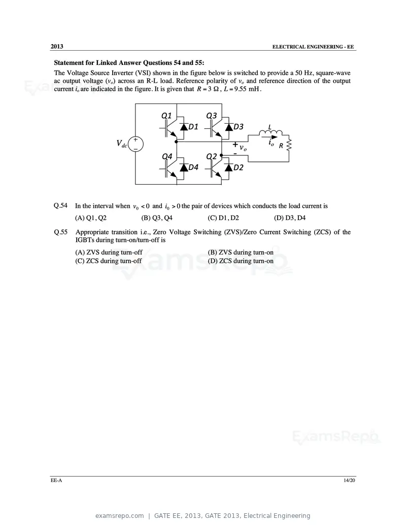
Text of page 15
2013                                                                               ELECTRICAL ENGINEERING - EE


 Statement for Linked Answer Questions 54 and 55:
 The Voltage Source Inverter (VSI) shown in the figure below is switched to provide a 50 Hz, square-wave
 ac output voltage (vo) across an R-L load. Reference polarity of vo and reference direction of the output
 current io are indicated in the figure. It is given that R = 3 Ω , L = 9.55 mH .


                                        Q1              Q3
                                                  D1              D3           L

                       V dc                                       + vo          io R
                                        Q4              Q2        ‐
                                                  D4              D2


 Q.54   In the interval when v 0 < 0 and i0 > 0 the pair of devices which conducts the load current is
        (A) Q1, Q2              (B) Q3, Q4               (C) D1, D2                (D) D3, D4

 Q.55   Appropriate transition i.e., Zero Voltage Switching (ZVS)/Zero Current Switching (ZCS) of the
        IGBTs during turn-on/turn-off is
        (A) ZVS during turn-off                          (B) ZVS during turn-on
        (C) ZCS during turn-off                          (D) ZCS during turn-on


EE-A                                                                                                      14/20
Text of page 16
2013                                                                            ELECTRICAL ENGINEERING - EE


General Aptitude (GA) Questions
Q.56 to Q.60 carry one mark each.
 Q.56   They were requested not to quarrel with others.
        Which one of the following options is the closest in meaning to the word quarrel?
        (A) make out             (B) call out           (C) dig out             (D) fall out

 Q.57   In the summer of 2012, in New Delhi, the mean temperature of Monday to Wednesday was 41°C
        and of Tuesday to Thursday was 43°C. If the temperature on Thursday was 15% higher than that of
        Monday, then the temperature in °C on Thursday was
        (A) 40                   (B) 43                 (C) 46                  (D) 49

 Q.58   Complete the sentence:
        Dare _______________ mistakes.
        (A) commit               (B) to commit          (C) committed           (D) committing

 Q.59   Choose the grammatically CORRECT sentence:
        (A) Two and two add four.
        (B) Two and two become four.
        (C) Two and two are four.
        (D) Two and two make four.

 Q.60   Statement: You can always give me a ring whenever you need.
        Which one of the following is the best inference from the above statement?
        (A) Because I have a nice caller tune.
        (B) Because I have a better telephone facility.
        (C) Because a friend in need is a friend indeed.
        (D) Because you need not pay towards the telephone bills when you give me a ring.


Q.61 to Q.65 carry two marks each.
 Q.61   What is the chance that a leap year, selected at random, will contain 53 Saturdays?
        (A) 2/7                  (B) 3/7                (C) 1/7                 (D) 5/7

 Q.62   Statement: There were different streams of freedom movements in colonial India carried out by the
        moderates, liberals, radicals, socialists, and so on.
        Which one of the following is the best inference from the above statement?
        (A) The emergence of nationalism in colonial India led to our Independence.
        (B) Nationalism in India emerged in the context of colonialism.
        (C) Nationalism in India is homogeneous.
        (D) Nationalism in India is heterogeneous.

 Q.63   The set of values of p for which the roots of the equation 3x2+2x+p(p–1) = 0 are of opposite sign is
        (A) (–∞, 0)              (B) (0, 1)             (C) (1, ∞)              (D) (0, ∞)

EE-A                                                                                                      15/20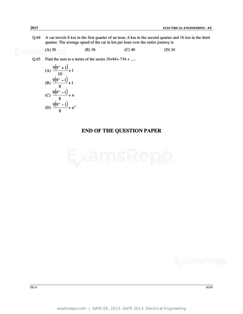
Text of page 17
2013                                                                            ELECTRICAL ENGINEERING - EE


 Q.64   A car travels 8 km in the first quarter of an hour, 6 km in the second quarter and 16 km in the third
        quarter. The average speed of the car in km per hour over the entire journey is
        (A) 30                  (B) 36                   (C) 40                 (D) 24

 Q.65   Find the sum to n terms of the series 10+84+ 734 + .....

        (A)
              (
            9 9n + 1 )
                     +1
               10
        (B)
              (
            9 9n − 1)+1
               8
        (C)
              (
            9 9n −1 )+n
               8
        (D)
              (
            9 9n − 1 )
                     + n2
                8


                              END OF THE QUESTION PAPER


EE-A                                                                                                      16/20
Text of page 18
SESSION - 2
Text of page 19
2013                                                                         Question Booklet Code
                                                                                                            B
                                EE : ELECTRICAL ENGINEERING
Duration: Three Hours                                                                        Maximum Marks: 100

Read the following instructions carefully.

       1. Do not open the seal of the Question Booklet until you are asked to do so by the invigilator.
       2. Take out the Optical Response Sheet (ORS) from this Question Booklet without breaking the seal
           and read the instructions printed on the ORS carefully. If you find that either:
           a. The Question Booklet Code printed at the right hand top corner of this page does not match with
                the Question Booklet Code at the right hand top corner of the ORS or
           b. The Question Paper Code preceding the Registration number on the ORS is not EE,
          then exchange the booklet immediately with a new sealed Question Booklet.
       3. On the right half hand side of the ORS, using ONLY a black ink ballpoint pen, (i) darken the
          appropriate bubble under each digit of your registration number and (ii) write your registration number,
          your name and name of the examination centre and put your signature at the specified location.
       4. This Question Booklet contains 20 pages including blank pages for rough work. After you are
          permitted to open the seal, check all pages and report discrepancies, if any, to the invigilator.
       5. There are a total of 65 questions carrying 100 marks. All these questions are of objective type. Each
          question has only one correct answer. Questions must be answered on the left hand side of the ORS
          by darkening the appropriate bubble (marked A, B, C, D) using ONLY a black ink ballpoint pen
          against the question number. For each question darken the bubble of the correct answer. More
          than one answer bubbled against a question will be treated as an incorrect response.
       6. Since bubbles darkened by the black ink ballpoint pen cannot be erased, candidates should darken the
          bubbles in the ORS very carefully.
       7. Questions Q.1 – Q.25 carry 1 mark each. Questions Q.26 – Q.55 carry 2 marks each. The 2 marks
          questions include two pairs of common data questions and two pairs of linked answer questions. The
          answer to the second question of the linked answer questions depends on the answer to the first
          question of the pair. If the first question in the linked pair is wrongly answered or is not attempted,
          then the answer to the second question in the pair will not be evaluated.
       8. Questions Q.56 – Q.65 belong to General Aptitude (GA) section and carry a total of 15 marks.
          Questions Q.56 – Q.60 carry 1 mark each, and questions Q.61 – Q.65 carry 2 marks each.
       9. Questions not attempted will result in zero mark and wrong answers will result in NEGATIVE
          marks. For all 1 mark questions, ⅓ mark will be deducted for each wrong answer. For all 2 marks
          questions, ⅔ mark will be deducted for each wrong answer. However, in the case of the linked
          answer question pair, there will be negative marks only for wrong answer to the first question and no
          negative marks for wrong answer to the second question.
       10. Calculator is allowed whereas charts, graph sheets or tables are NOT allowed in the examination hall.
       11. Rough work can be done on the Question Booklet itself. Blank pages are provided at the end of the
           Question Booklet for rough work.
       12. Before the start of the examination, write your name and registration number in the space provided
           below using a black ink ballpoint pen.

              Name

              Registration Number       EE

EE-B                                                                                                          1/20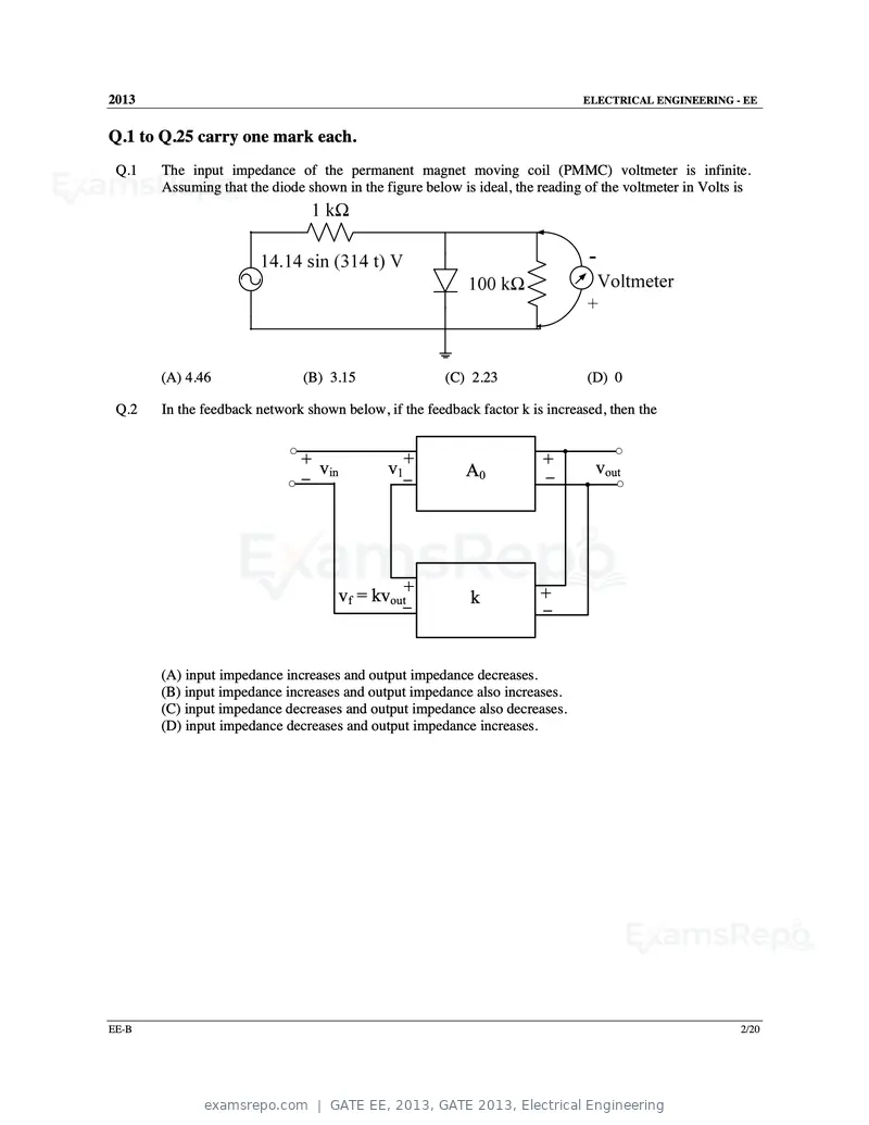
Text of page 20
2013                                                                          ELECTRICAL ENGINEERING - EE


Q.1 to Q.25 carry one mark each.
 Q.1   The input impedance of the permanent magnet moving coil (PMMC) voltmeter is infinite.
       Assuming that the diode shown in the figure below is ideal, the reading of the voltmeter in Volts is


       (A) 4.46                (B) 3.15                  (C) 2.23              (D) 0

 Q.2   In the feedback network shown below, if the feedback factor k is increased, then the


                              + v                    +                 +        vout
                                    in          v1          A0          –
                              –                      –


                                         vf = kvout+        k          +
                                                  –                    –


       (A) input impedance increases and output impedance decreases.
       (B) input impedance increases and output impedance also increases.
       (C) input impedance decreases and output impedance also decreases.
       (D) input impedance decreases and output impedance increases.


EE-B                                                                                                     2/20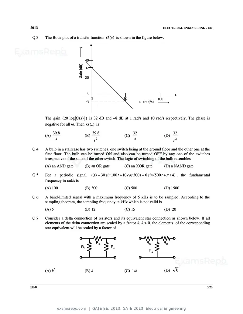
Text of page 21
2013                                                                           ELECTRICAL ENGINEERING - EE


 Q.3   The Bode plot of a transfer function G (s ) is shown in the figure below.


                           Gain (dB)


       The gain (20 log G ( s ) ) is 32 dB and –8 dB at 1 rad/s and 10 rad/s respectively. The phase is
       negative for all ω. Then G (s) is

             39.8                            39.8                  32                    32
       (A)                             (B)                   (C)                   (D)
              s                                s2                   s                    s2

 Q.4   A bulb in a staircase has two switches, one switch being at the ground floor and the other one at the
       first floor. The bulb can be turned ON and also can be turned OFF by any one of the switches
       irrespective of the state of the other switch. The logic of switching of the bulb resembles
       (A) an AND gate                 (B) an OR gate        (C) an XOR gate       (D) a NAND gate

 Q.5   For a periodic signal v(t ) = 30 sin 100 t + 10 cos 300 t + 6 sin (500 t + π / 4) , the fundamental
       frequency in rad/s is
       (A) 100                         (B) 300               (C) 500               (D) 1500

 Q.6   A band-limited signal with a maximum frequency of 5 kHz is to be sampled. According to the
       sampling theorem, the sampling frequency in kHz which is not valid is
       (A) 5                           (B) 12                (C) 15                (D) 20

 Q.7   Consider a delta connection of resistors and its equivalent star connection as shown below. If all
       elements of the delta connection are scaled by a factor k, k > 0, the elements of the corresponding
       star equivalent will be scaled by a factor of


                                                Ra                      RC     RB
                                Rb                      Rc
                                                                          RA


       (A) k2                          (B) k                 (C) 1/k               (D)    k


EE-B                                                                                                      3/20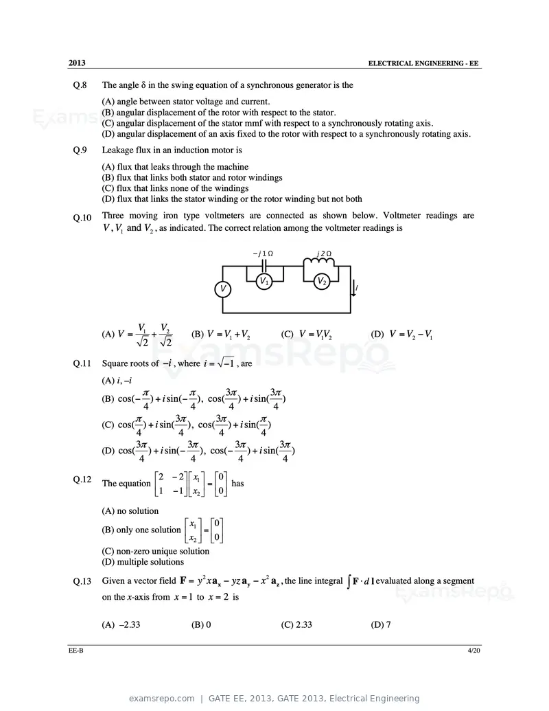
Text of page 22
2013 ELECTRICAL ENGINEERING - EE
Q.8 The angle δ in the swing equation of a synchronous generator is the
(A) angle between stator voltage and current.
(B) angular displacement of the rotor with respect to the stator.
(C) angular displacement of the stator mmf with respect to a synchronously rotating axis.
(D) angular displacement of an axis fixed to the rotor with respect to a synchronously rotating axis.
Q.9 Leakage flux in an induction motor is
(A) flux that leaks through the machine
(B) flux that links both stator and rotor windings
(C) flux that links none of the windings
(D) flux that links the stator winding or the rotor winding but not both
Q.10 Three moving iron type voltmeters are connected as shown below. Voltmeter readings are
V , V1 and V2 , as indicated. The correct relation among the voltmeter readings is
V1 V2
(A) V = + (B) V = V1 + V2 (C) V = VV
1 2 (D) V = V2 − V1
2 2
Q.11 Square roots of −i , where i = −1 , are
(A) i, –i
π π 3π 3π
(B) cos( − ) + i sin( − ), cos( ) + i sin( )
4 4 4 4
π 3π 3π π
(C) cos( ) + i sin( ), cos( ) + i sin( )
4 4 4 4
3π 3π 3π 3π
(D) cos( ) + i sin( − ), cos( − ) + i sin( )
4 4 4 4
Q.12 2 − 2 x1 0
The equation = has
1 − 1 x2 0
(A) no solution
x 0
(B) only one solution 1 =
x2 0
(C) non-zero unique solution
(D) multiple solutions
Given a vector field F = y x a x − yz a y − x a z , the line integral ∫ F ⋅ d l evaluated along a segment
2 2
Q.13
on the x-axis from x = 1 to x = 2 is
(A) –2.33 (B) 0 (C) 2.33 (D) 7
EE-B 4/20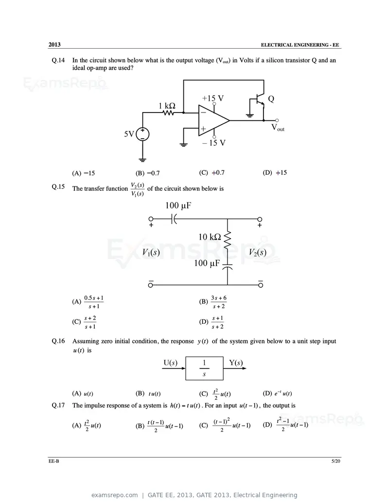
Text of page 23
2013                                                                                          ELECTRICAL ENGINEERING - EE


 Q.14   In the circuit shown below what is the output voltage (Vout) in Volts if a silicon transistor Q and an
        ideal op-amp are used?


        (A)    15                 (B)     0.7                   (C)     0.7                   (D)     15

 Q.15                           V2 ( s )
        The transfer function            of the circuit shown below is
                                V1 ( s )


              0.5 s + 1                                               3s + 6
        (A)                                                     (B)
                s +1                                                   s+2
              s+2                                                     s +1
        (C)                                                     (D)
              s +1                                                    s+2

 Q.16   Assuming zero initial condition, the response y (t ) of the system given below to a unit step input
        u (t ) is


                                                                                              (D) e −t u (t )
                                                                     2
        (A) u (t )                (B) t u (t )                  (C) t u (t )
                                                                       2
 Q.17   The impulse response of a system is h(t ) = t u (t ) . For an input u (t − 1) , the output is

              2                         t (t − 1)                     (t − 1) 2                      t2 −1
        (A) t u (t )              (B)               u (t − 1)   (C)               u (t − 1)   (D)            u (t − 1)
              2                            2                               2                           2


EE-B                                                                                                                     5/20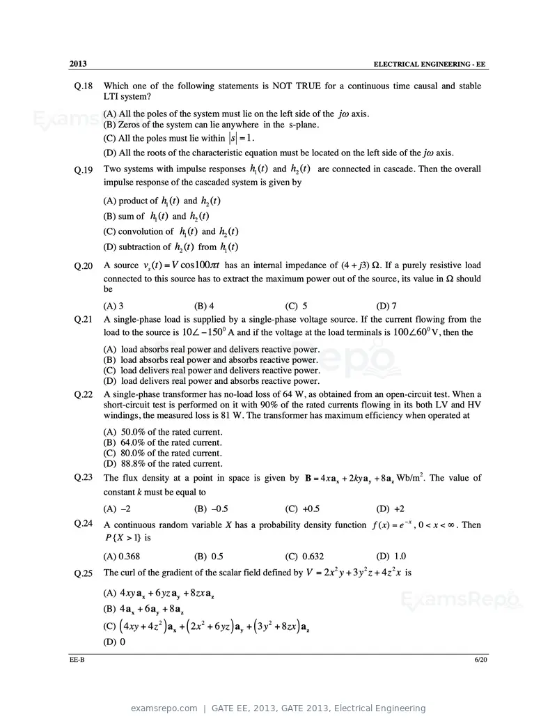
Text of page 24
2013                                                                                ELECTRICAL ENGINEERING - EE


 Q.18   Which one of the following statements is NOT TRUE for a continuous time causal and stable
        LTI system?
        (A) All the poles of the system must lie on the left side of the jω axis.
        (B) Zeros of the system can lie anywhere in the s-plane.
        (C) All the poles must lie within s = 1.
        (D) All the roots of the characteristic equation must be located on the left side of the jω axis.
 Q.19   Two systems with impulse responses h1 (t ) and h2 (t ) are connected in cascade. Then the overall
        impulse response of the cascaded system is given by
        (A) product of h1 (t ) and h2 (t )
        (B) sum of h1 (t ) and h2 (t )
        (C) convolution of h1 (t ) and h2 (t )
        (D) subtraction of h2 (t ) from h1 (t )

 Q.20   A source vs (t ) = V cos100π t has an internal impedance of (4 + j3) Ω. If a purely resistive load
        connected to this source has to extract the maximum power out of the source, its value in Ω should
        be
        (A) 3                   (B) 4                   (C) 5                    (D) 7
 Q.21   A single-phase load is supplied by a single-phase voltage source. If the current flowing from the
        load to the source is 10∠ − 1500 A and if the voltage at the load terminals is 100∠600 V, then the
        (A) load absorbs real power and delivers reactive power.
        (B) load absorbs real power and absorbs reactive power.
        (C) load delivers real power and delivers reactive power.
        (D) load delivers real power and absorbs reactive power.
 Q.22   A single-phase transformer has no-load loss of 64 W, as obtained from an open-circuit test. When a
        short-circuit test is performed on it with 90% of the rated currents flowing in its both LV and HV
        windings, the measured loss is 81 W. The transformer has maximum efficiency when operated at
        (A) 50.0% of the rated current.
        (B) 64.0% of the rated current.
        (C) 80.0% of the rated current.
        (D) 88.8% of the rated current.
 Q.23   The flux density at a point in space is given by B = 4 x a x + 2ky a y + 8 a z Wb/m2. The value of
        constant k must be equal to
        (A) –2                          (B) –0.5           (C) +0.5                 (D) +2
 Q.24   A continuous random variable X has a probability density function f ( x) = e − x , 0 < x < ∞ . Then
        P { X > 1} is
        (A) 0.368                       (B) 0.5            (C) 0.632                (D) 1.0
 Q.25   The curl of the gradient of the scalar field defined by V = 2 x y + 3 y z + 4 z 2 x is
                                                                        2       2


        (A) 4 xy a x + 6 yz a y + 8 zx a z
        (B) 4 a x + 6 a y + 8 a z

             (            )         (              )   (      )
        (C) 4 xy + 4 z 2 a x + 2 x 2 + 6 yz a y + 3 y 2 + 8 zx a z
        (D) 0
EE-B                                                                                                        6/20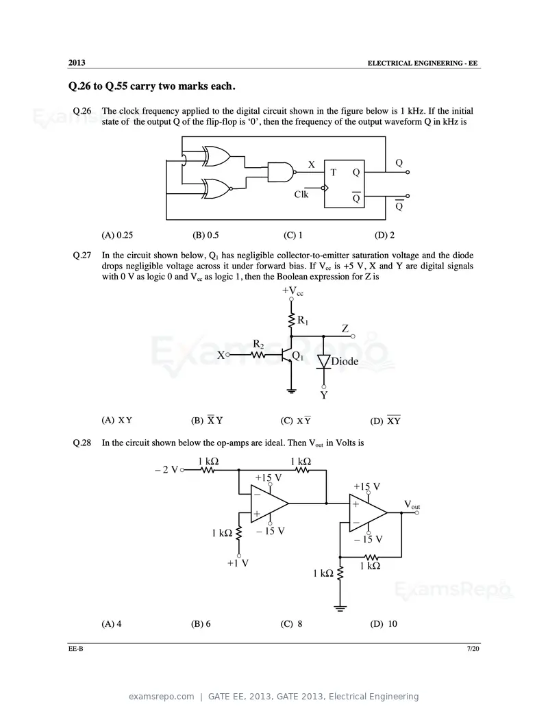
Text of page 25
2013                                                                              ELECTRICAL ENGINEERING - EE


Q.26 to Q.55 carry two marks each.

 Q.26   The clock frequency applied to the digital circuit shown in the figure below is 1 kHz. If the initial
        state of the output Q of the flip-flop is ‘0’, then the frequency of the output waveform Q in kHz is


        (A) 0.25                (B) 0.5                  (C) 1                     (D) 2

 Q.27   In the circuit shown below, Q1 has negligible collector-to-emitter saturation voltage and the diode
        drops negligible voltage across it under forward bias. If Vcc is +5 V, X and Y are digital signals
        with 0 V as logic 0 and Vcc as logic 1, then the Boolean expression for Z is


        (A) X Y                 (B) X Y                 (C) X Y                   (D) XY

 Q.28   In the circuit shown below the op-amps are ideal. Then Vout in Volts is


        (A) 4                   (B) 6                   (C) 8                     (D) 10

EE-B                                                                                                       7/20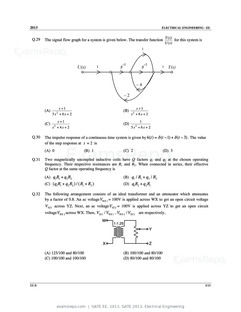
Text of page 26
2013                                                                               ELECTRICAL ENGINEERING - EE


                                                                                     Y (s)
 Q.29   The signal flow graph for a system is given below. The transfer function            for this system is
                                                                                     U ( s)


                       s +1                                          s +1
        (A)                                               (B)
              5s + 6s + 2
                   2
                                                                s + 6s + 2
                                                                 2


                   s +1                                                  1
        (C)                                               (D)
              s + 4s + 2
               2
                                                                5s + 6s + 2
                                                                     2


 Q.30   The impulse response of a continuous time system is given by h(t ) = δ (t − 1) + δ (t − 3) . The value
        of the step response at t = 2 is
        (A) 0                     (B) 1                   (C) 2                     (D) 3

 Q.31   Two magnetically uncoupled inductive coils have Q factors q1 and q2 at the chosen operating
        frequency. Their respective resistances are R1 and R2. When connected in series, their effective
        Q factor at the same operating frequency is

        (A) q1 R1 + q2 R2                                 (B) q1 / R1 + q2 / R2
        (C) (q1R1 + q2 R2 ) / ( R1 + R2 )                 (D) q1R2 + q2 R1

 Q.32   The following arrangement consists of an ideal transformer and an attenuator which attenuates
        by a factor of 0.8. An ac voltage VWX 1 = 100V is applied across WX to get an open circuit voltage
        VYZ 1 across YZ. Next, an ac voltage VYZ 2 = 100V is applied across YZ to get an open circuit
        voltage VWX 2 across WX. Then, VYZ 1 / VWX 1 , VWX 2 / VYZ 2 are respectively,
                                             W
                                                    1:1.25
                                                                             Y


                                             X                               Z

        (A) 125/100 and 80/100                            (B) 100/100 and 80/100
        (C) 100/100 and 100/100                           (D) 80/100 and 80/100


EE-B                                                                                                             8/20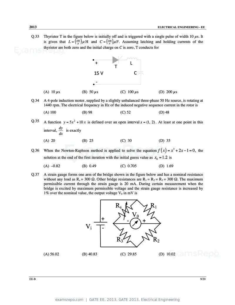
Text of page 27
2013                                                                                ELECTRICAL ENGINEERING - EE


 Q.33   Thyristor T in the figure below is initially off and is triggered with a single pulse of width 10 µs. It
        is given that L = (100π
                                ) µ H and C = (100π )µ F. Assuming latching and holding currents of the
        thyristor are both zero and the initial charge on C is zero, T conducts for


                                          +                        L
                                                       T
                                          15 V                         C
                                          ‐
        (A) 10 µs                (B) 50 µs                 (C) 100 µs                (D) 200 µs

 Q.34   A 4-pole induction motor, supplied by a slightly unbalanced three-phase 50 Hz source, is rotating at
        1440 rpm. The electrical frequency in Hz of the induced negative sequence current in the rotor is
        (A) 100                  (B) 98                    (C) 52                    (D) 48

 Q.35   A function y = 5 x 2 + 10 x is defined over an open interval x = (1, 2) . At least at one point in this
                  dy
        interval,    is exactly
                  dx
        (A) 20                   (B) 25                    (C) 30                    (D) 35

        When the Newton-Raphson method is applied to solve the equation f ( x ) = x + 2 x − 1 = 0, the
                                                                                                 3
 Q.36
        solution at the end of the first iteration with the initial guess value as x0 = 1.2 is

        (A) –0.82                (B) 0.49                  (C) 0.705                 (D) 1.69

 Q.37   A strain gauge forms one arm of the bridge shown in the figure below and has a nominal resistance
        without any load as Rs = 300 Ω. Other bridge resistances are R1 = R2 = R3 = 300 Ω. The maximum
        permissible current through the strain gauge is 20 mA. During certain measurement when the
        bridge is excited by maximum permissible voltage and the strain gauge resistance is increased by
        1% over the nominal value, the output voltage V0 in mV is


                                                        Rs                     R1
                                                                    V0
                                              +                ‐           +
                                    Vi        ‐
                                                        R3                       R2

        (A) 56.02                (B) 40.83                 (C) 29.85                 (D) 10.02


EE-B                                                                                                          9/20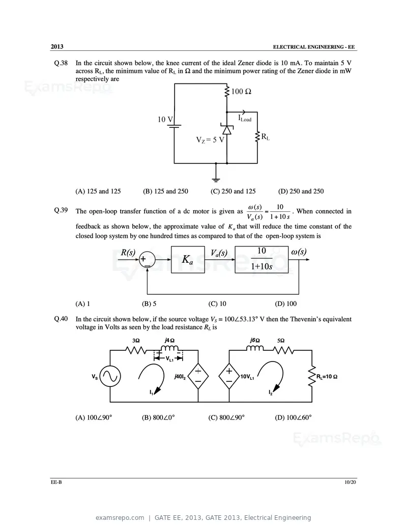
Text of page 28
2013                                                                                   ELECTRICAL ENGINEERING - EE


 Q.38   In the circuit shown below, the knee current of the ideal Zener diode is 10 mA. To maintain 5 V
        across RL, the minimum value of RL in Ω and the minimum power rating of the Zener diode in mW
        respectively are


        (A) 125 and 125           (B) 125 and 250       (C) 250 and 125                 (D) 250 and 250

                                                                      ω (s)      10
 Q.39   The open-loop transfer function of a dc motor is given as             =        . When connected in
                                                                    V a ( s ) 1 + 10 s
        feedback as shown below, the approximate value of K a that will reduce the time constant of the
        closed loop system by one hundred times as compared to that of the open-loop system is

                          R(s)                          Va(s)             10                 ω(s)
                                  +_               Ka
                                                                       1+10s


        (A) 1                     (B) 5                 (C) 10                         (D) 100

 Q.40   In the circuit shown below, if the source voltage VS = 100∠53.13° V then the Thevenin’s equivalent
        voltage in Volts as seen by the load resistance RL is
                             3Ω           j4 Ω                        j6 Ω              5Ω


                                          VL1


                VS                              j40I2             10VL1                              RL=10 Ω

                                    I1                                            I2


        (A) 100∠90°               (B) 800∠0°            (C) 800∠90°                    (D) 100∠60°


EE-B                                                                                                           10/20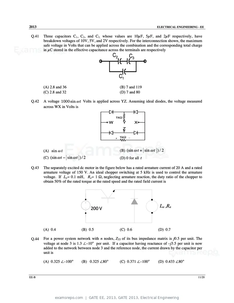
Text of page 29
2013                                                                             ELECTRICAL ENGINEERING - EE


 Q.41   Three capacitors C1, C2, and C3, whose values are 10µF, 5µF, and 2µF respectively, have
        breakdown voltages of 10V, 5V, and 2V respectively. For the interconnection shown, the maximum
        safe voltage in Volts that can be applied across the combination and the corresponding total charge
        in µC stored in the effective capacitance across the terminals are respectively
                                                   C2           C3


                                                          C1
        (A) 2.8 and 36                                    (B) 7 and 119
        (C) 2.8 and 32                                    (D) 7 and 80

 Q.42   A voltage 1000 sin ω t Volts is applied across YZ. Assuming ideal diodes, the voltage measured
        across WX in Volts is

                                                      1kΩ
                                                  W         Y        X
                                                            Z

                                                      +   1kΩ   _


        (A) sin ω t                                       (B) (sin ω t + sin ω t ) / 2
        (C) (sin ω t − sin ω t ) / 2                      (D) 0 for all t

 Q.43   The separately excited dc motor in the figure below has a rated armature current of 20 A and a rated
        armature voltage of 150 V. An ideal chopper switching at 5 kHz is used to control the armature
        voltage. If La= 0.1 mH, Ra= 1 Ω, neglecting armature reaction, the duty ratio of the chopper to
        obtain 50% of the rated torque at the rated speed and the rated field current is


                                       200 V                                       La ,Ra


        (A) 0.4                  (B) 0.5                  (C) 0.6                 (D) 0.7

 Q.44   For a power system network with n nodes, Z33 of its bus impedance matrix is j0.5 per unit. The
        voltage at node 3 is 1.3 ∠–10° per unit. If a capacitor having reactance of –j3.5 per unit is now
        added to the network between node 3 and the reference node, the current drawn by the capacitor per
        unit is

        (A) 0.325 ∠–100°         (B) 0.325 ∠80°           (C) 0.371 ∠–100°        (D) 0.433 ∠80°


EE-B                                                                                                     11/20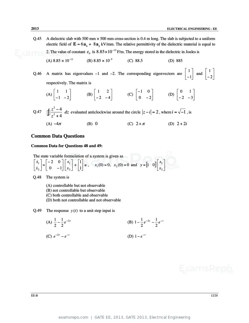
Text of page 30
2013 ELECTRICAL ENGINEERING - EE
Q.45 A dielectric slab with 500 mm × 500 mm cross-section is 0.4 m long. The slab is subjected to a uniform
electric field of E = 6 a x + 8 a y kV/mm. The relative permittivity of the dielectric material is equal to
2. The value of constant ε 0 is 8.85 × 10 −12 F/m. The energy stored in the dielectric in Joules is
(A) 8.85 × 10⁻¹¹ (B) 8.85 × 10⁻⁵ (C) 88.5 (D) 885
1 1
Q.46 A matrix has eigenvalues –1 and –2. The corresponding eigenvectors are and
−1
− 2
respectively. The matrix is
1 1 1 2 − 1 0 0 1
(A) (B) (C) (D)
− 1 − 2 − 2 − 4 0 − 2 − 2 − 3
z2 − 4
Q.47
∫ z 2 + 4 dz evaluated anticlockwise around the circle z − i = 2 , where i = −1 , is
(A) −4π (B) 0 (C) 2 + π (D) 2 + 2i
Common Data Questions
Common Data for Questions 48 and 49:
The state variable formulation of a system is given as
x&1 − 2 0 x1 1 x1
x& = 0 − 1 x + 1 u , x1 (0) = 0, x 2 (0) = 0 and y = [1 0] x
2 2 2
Q.48 The system is
(A) controllable but not observable
(B) not controllable but observable
(C) both controllable and observable
(D) both not controllable and not observable
Q.49 The response y (t ) to a unit step input is
1 1 −2 t 1 −2 t 1 − t
(A) − e (B) 1 − e − e
2 2 2 2
(C) e −2 t − e − t (D) 1 − e − t
EE-B 12/20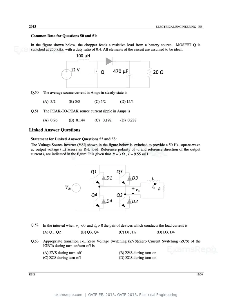
Text of page 31
2013                                                                              ELECTRICAL ENGINEERING - EE


 Common Data for Questions 50 and 51:

 In the figure shown below, the chopper feeds a resistive load from a battery source. MOSFET Q is
 switched at 250 kHz, with a duty ratio of 0.4. All elements of the circuit are assumed to be ideal.
                             100 µH


                          12 V                          470 µF
                                               Q                               20 Ω


 Q.50   The average source current in Amps in steady-state is

        (A) 3/2         (B) 5/3          (C) 5/2          (D) 15/4

 Q.51   The PEAK-TO-PEAK source current ripple in Amps is

        (A) 0.96        (B) 0.144        (C) 0.192        (D) 0.288

Linked Answer Questions
 Statement for Linked Answer Questions 52 and 53:
 The Voltage Source Inverter (VSI) shown in the figure below is switched to provide a 50 Hz, square-wave
 ac output voltage (vo) across an R-L load. Reference polarity of vo and reference direction of the output
 current io are indicated in the figure. It is given that R = 3 Ω , L = 9.55 mH .


                                       Q1                Q3
                                                   D1             D3          L

                      Vdc                                        + vo          io R
                                       Q4                Q2      ‐
                                                   D4             D2


 Q.52   In the interval when v 0 < 0 and i0 > 0 the pair of devices which conducts the load current is
        (A) Q1, Q2                (B) Q3, Q4              (C) D1, D2               (D) D3, D4

 Q.53   Appropriate transition i.e., Zero Voltage Switching (ZVS)/Zero Current Switching (ZCS) of the
        IGBTs during turn-on/turn-off is
        (A) ZVS during turn-off                           (B) ZVS during turn-on
        (C) ZCS during turn-off                           (D) ZCS during turn-on


EE-B                                                                                                     13/20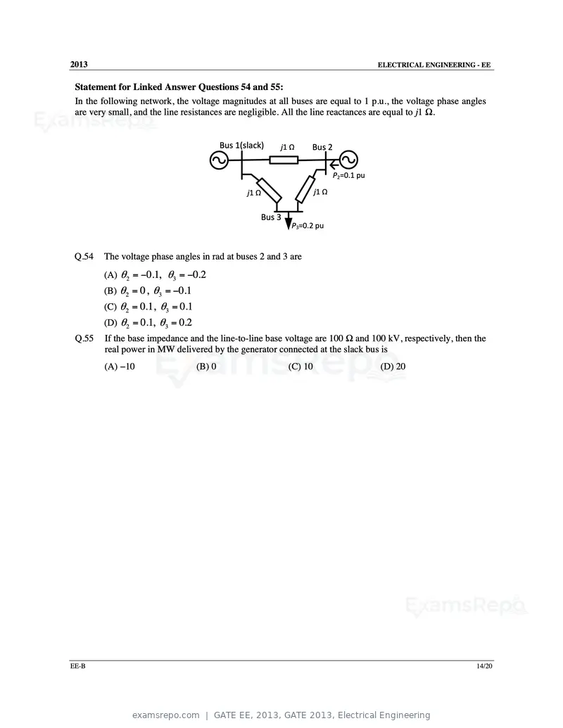
Text of page 32
2013                                                                                        ELECTRICAL ENGINEERING - EE


 Statement for Linked Answer Questions 54 and 55:
 In the following network, the voltage magnitudes at all buses are equal to 1 p.u., the voltage phase angles
 are very small, and the line resistances are negligible. All the line reactances are equal to j1 Ω.


                                          Bus 1(slack)      j1 Ω     Bus 2

                                                                                P2=0.1 pu

                                                 j1 Ω                    j1 Ω


                                                        Bus 3
                                                                P3=0.2 pu


 Q.54   The voltage phase angles in rad at buses 2 and 3 are
        (A) θ 2 = −0.1, θ3 = −0.2
        (B) θ 2 = 0, θ3 = −0.1
        (C) θ 2 = 0.1, θ3 = 0.1
        (D) θ 2 = 0.1, θ3 = 0.2
 Q.55   If the base impedance and the line-to-line base voltage are 100 Ω and 100 kV, respectively, then the
        real power in MW delivered by the generator connected at the slack bus is
        (A) −10                   (B) 0                         (C) 10                      (D) 20


EE-B                                                                                                               14/20
Text of page 33
2013                                                                            ELECTRICAL ENGINEERING - EE


General Aptitude (GA) Questions
Q.56 to Q.60 carry one mark each.
 Q.56   Complete the sentence:
        Dare _______________ mistakes.
        (A) commit              (B) to commit            (C) committed          (D) committing

 Q.57   They were requested not to quarrel with others.
        Which one of the following options is the closest in meaning to the word quarrel?
        (A) make out            (B) call out             (C) dig out            (D) fall out

 Q.58   Statement: You can always give me a ring whenever you need.
        Which one of the following is the best inference from the above statement?
        (A) Because I have a nice caller tune.
        (B) Because I have a better telephone facility.
        (C) Because a friend in need is a friend indeed.
        (D) Because you need not pay towards the telephone bills when you give me a ring.

 Q.59   In the summer of 2012, in New Delhi, the mean temperature of Monday to Wednesday was 41°C
        and of Tuesday to Thursday was 43°C. If the temperature on Thursday was 15% higher than that of
        Monday, then the temperature in °C on Thursday was
        (A) 40                  (B) 43                   (C) 46                 (D) 49

 Q.60   Choose the grammatically CORRECT sentence:
        (A) Two and two add four.
        (B) Two and two become four.
        (C) Two and two are four.
        (D) Two and two make four.
Q.61 to Q.65 carry two marks each.
 Q.61   The set of values of p for which the roots of the equation 3x2+2x+p(p–1) = 0 are of opposite sign is
        (A) (–∞, 0)             (B) (0, 1)               (C) (1, ∞)             (D) (0, ∞)

 Q.62   What is the chance that a leap year, selected at random, will contain 53 Saturdays?
        (A) 2/7                 (B) 3/7                  (C) 1/7                (D) 5/7

 Q.63   Find the sum to n terms of the series 10+84+ 734 + .....

        (A)
              (
            9 9n + 1  )
                     +1
               10
        (B)
              (
            9 9n − 1  )
                     +1
               8
        (C)
              (
            9 9n −1   )
                     +n
               8
        (D)
              (
            9 9n − 1  )
                     + n2
                8

EE-B                                                                                                      15/20
Text of page 34
2013                                                                            ELECTRICAL ENGINEERING - EE


 Q.64   Statement: There were different streams of freedom movements in colonial India carried out by the
        moderates, liberals, radicals, socialists, and so on.
        Which one of the following is the best inference from the above statement?
        (A) The emergence of nationalism in colonial India led to our Independence.
        (B) Nationalism in India emerged in the context of colonialism.
        (C) Nationalism in India is homogeneous.
        (D) Nationalism in India is heterogeneous.

 Q.65   A car travels 8 km in the first quarter of an hour, 6 km in the second quarter and 16 km in the third
        quarter. The average speed of the car in km per hour over the entire journey is
        (A) 30                  (B) 36                  (C) 40                   (D) 24


                              END OF THE QUESTION PAPER


EE-B                                                                                                      16/20
Text of page 35
SESSION - 3
Text of page 36
2013                                                                         Question Booklet Code
                                                                                                            C
                                EE : ELECTRICAL ENGINEERING
Duration: Three Hours                                                                        Maximum Marks: 100

Read the following instructions carefully.

       1. Do not open the seal of the Question Booklet until you are asked to do so by the invigilator.
       2. Take out the Optical Response Sheet (ORS) from this Question Booklet without breaking the seal
           and read the instructions printed on the ORS carefully. If you find that either:
           a. The Question Booklet Code printed at the right hand top corner of this page does not match with
                the Question Booklet Code at the right hand top corner of the ORS or
           b. The Question Paper Code preceding the Registration number on the ORS is not EE,
          then exchange the booklet immediately with a new sealed Question Booklet.
       3. On the right half hand side of the ORS, using ONLY a black ink ballpoint pen, (i) darken the
          appropriate bubble under each digit of your registration number and (ii) write your registration number,
          your name and name of the examination centre and put your signature at the specified location.
       4. This Question Booklet contains 20 pages including blank pages for rough work. After you are
          permitted to open the seal, check all pages and report discrepancies, if any, to the invigilator.
       5. There are a total of 65 questions carrying 100 marks. All these questions are of objective type. Each
          question has only one correct answer. Questions must be answered on the left hand side of the ORS
          by darkening the appropriate bubble (marked A, B, C, D) using ONLY a black ink ballpoint pen
          against the question number. For each question darken the bubble of the correct answer. More
          than one answer bubbled against a question will be treated as an incorrect response.
       6. Since bubbles darkened by the black ink ballpoint pen cannot be erased, candidates should darken the
          bubbles in the ORS very carefully.
       7. Questions Q.1 – Q.25 carry 1 mark each. Questions Q.26 – Q.55 carry 2 marks each. The 2 marks
          questions include two pairs of common data questions and two pairs of linked answer questions. The
          answer to the second question of the linked answer questions depends on the answer to the first
          question of the pair. If the first question in the linked pair is wrongly answered or is not attempted,
          then the answer to the second question in the pair will not be evaluated.
       8. Questions Q.56 – Q.65 belong to General Aptitude (GA) section and carry a total of 15 marks.
          Questions Q.56 – Q.60 carry 1 mark each, and questions Q.61 – Q.65 carry 2 marks each.
       9. Questions not attempted will result in zero mark and wrong answers will result in NEGATIVE
          marks. For all 1 mark questions, ⅓ mark will be deducted for each wrong answer. For all 2 marks
          questions, ⅔ mark will be deducted for each wrong answer. However, in the case of the linked
          answer question pair, there will be negative marks only for wrong answer to the first question and no
          negative marks for wrong answer to the second question.
       10. Calculator is allowed whereas charts, graph sheets or tables are NOT allowed in the examination hall.
       11. Rough work can be done on the Question Booklet itself. Blank pages are provided at the end of the
           Question Booklet for rough work.
       12. Before the start of the examination, write your name and registration number in the space provided
           below using a black ink ballpoint pen.

              Name

              Registration Number       EE

EE-C                                                                                                          1/20
Text of page 37
2013                                                                                 ELECTRICAL ENGINEERING - EE


Q.1 to Q.25 carry one mark each.

 Q.1   The curl of the gradient of the scalar field defined by V = 2 x 2 y + 3 y 2 z + 4 z 2 x is

       (A) 4 xy a x + 6 yz a y + 8 zx a z
       (B) 4 a x + 6 a y + 8 a z

            (            )         (              )   (        )
       (C) 4 xy + 4 z 2 a x + 2 x 2 + 6 yz a y + 3 y 2 + 8 zx a z
       (D) 0

 Q.2   A continuous random variable X has a probability density function f ( x) = e − x , 0 < x < ∞ . Then
       P { X > 1} is
       (A) 0.368                       (B) 0.5              (C) 0.632                 (D) 1.0

 Q.3   The flux density at a point in space is given by B = 4 x a x + 2ky a y + 8 a z Wb/m2. The value of
       constant k must be equal to
       (A) –2                          (B) –0.5             (C) +0.5                  (D) +2

 Q.4   A single-phase transformer has no-load loss of 64 W, as obtained from an open-circuit test. When a
       short-circuit test is performed on it with 90% of the rated currents flowing in its both LV and HV
       windings, the measured loss is 81 W. The transformer has maximum efficiency when operated at
       (A) 50.0% of the rated current.
       (B) 64.0% of the rated current.
       (C) 80.0% of the rated current.
       (D) 88.8% of the rated current.

 Q.5   A single-phase load is supplied by a single-phase voltage source. If the current flowing from the
       load to the source is 10∠ − 1500 A and if the voltage at the load terminals is 100∠600 V, then the
       (A) load absorbs real power and delivers reactive power.
       (B) load absorbs real power and absorbs reactive power.
       (C) load delivers real power and delivers reactive power.
       (D) load delivers real power and absorbs reactive power.

 Q.6   A source vs (t ) = V cos100π t has an internal impedance of (4 + j3) Ω. If a purely resistive load
       connected to this source has to extract the maximum power out of the source, its value in Ω should
       be
       (A) 3                           (B) 4                (C) 5                     (D) 7

 Q.7   Two systems with impulse responses h1 (t ) and h2 (t ) are connected in cascade. Then the overall
       impulse response of the cascaded system is given by

       (A) product of h1 (t ) and h2 (t )
       (B) sum of h1 (t ) and h2 (t )
       (C) convolution of h1 (t ) and h2 (t )
       (D) subtraction of h2 (t ) from h1 (t )
EE-C                                                                                                         2/20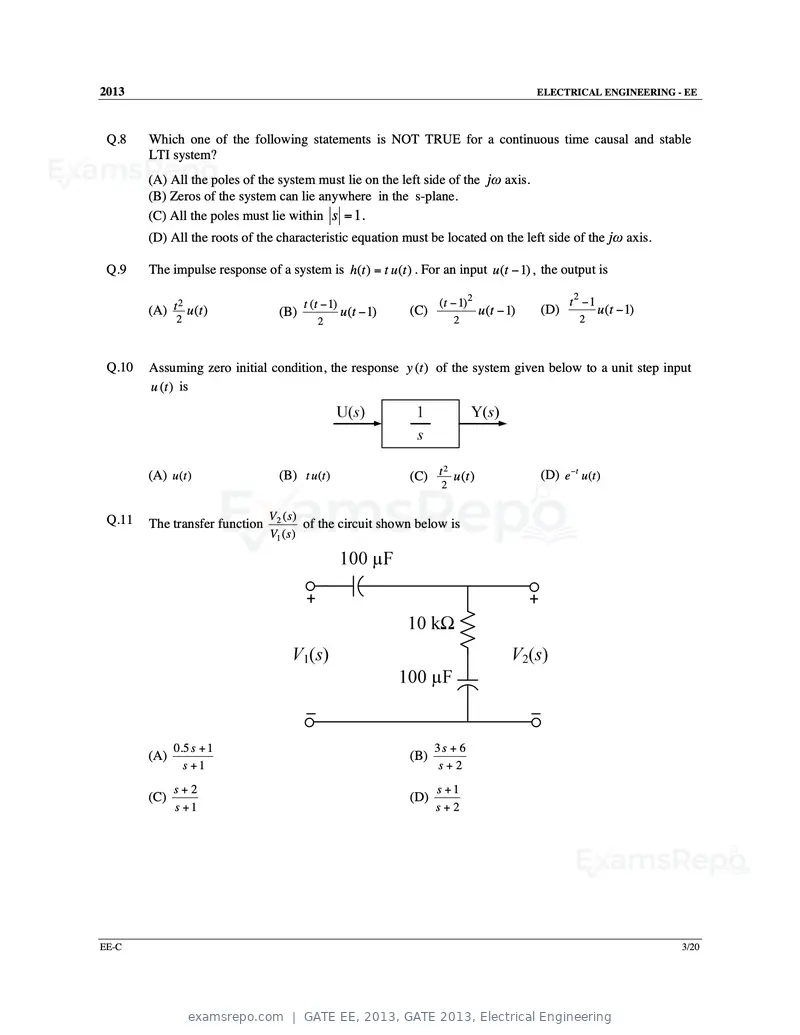
Text of page 38
2013                                                                                          ELECTRICAL ENGINEERING - EE


 Q.8    Which one of the following statements is NOT TRUE for a continuous time causal and stable
        LTI system?
        (A) All the poles of the system must lie on the left side of the jω axis.
        (B) Zeros of the system can lie anywhere in the s-plane.
        (C) All the poles must lie within s = 1.
        (D) All the roots of the characteristic equation must be located on the left side of the jω axis.

 Q.9    The impulse response of a system is h(t ) = t u (t ) . For an input u (t − 1) , the output is

              2                         t (t − 1)                     (t − 1) 2                      t2 −1
        (A) t u (t )              (B)               u (t − 1)   (C)               u (t − 1)   (D)            u (t − 1)
              2                            2                               2                           2


 Q.10   Assuming zero initial condition, the response y (t ) of the system given below to a unit step input
        u (t ) is


                                                                                              (D) e −t u (t )
                                                                     2
        (A) u (t )                (B) t u (t )                  (C) t u (t )
                                                                       2


 Q.11                           V2 ( s )
        The transfer function            of the circuit shown below is
                                V1 ( s )


              0.5 s + 1                                               3s + 6
        (A)                                                     (B)
                s +1                                                   s+2
              s+2                                                     s +1
        (C)                                                     (D)
              s +1                                                    s+2


EE-C                                                                                                                     3/20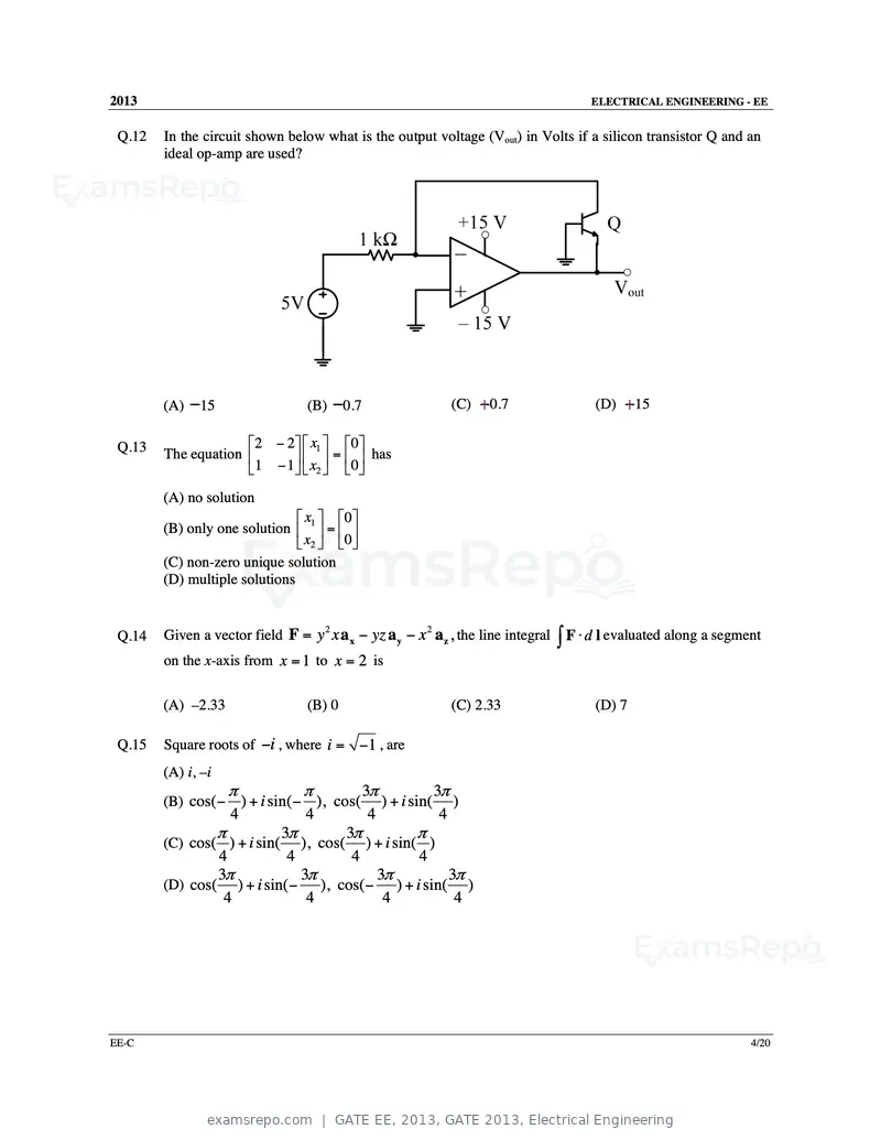
Text of page 39
2013 ELECTRICAL ENGINEERING - EE
Q.12 In the circuit shown below what is the output voltage (Vout) in Volts if a silicon transistor Q and an
ideal op-amp are used?
(A) 15 (B) 0.7 (C) 0.7 (D) 15
Q.13 2 − 2 x1 0
The equation = has
1 − 1 x2 0
(A) no solution
x 0
(B) only one solution 1 =
x2 0
(C) non-zero unique solution
(D) multiple solutions
Given a vector field F = y x a x − yz a y − x a z , the line integral ∫ F ⋅ d l evaluated along a segment
2 2
Q.14
on the x-axis from x = 1 to x = 2 is
(A) –2.33 (B) 0 (C) 2.33 (D) 7
Q.15 Square roots of −i , where i = −1 , are
(A) i, –i
π π 3π 3π
(B) cos( − ) + i sin( − ), cos( ) + i sin( )
4 4 4 4
π 3π 3π π
(C) cos( ) + i sin( ), cos( ) + i sin( )
4 4 4 4
3π 3π 3π 3π
(D) cos( ) + i sin( − ), cos( − ) + i sin( )
4 4 4 4
EE-C 4/20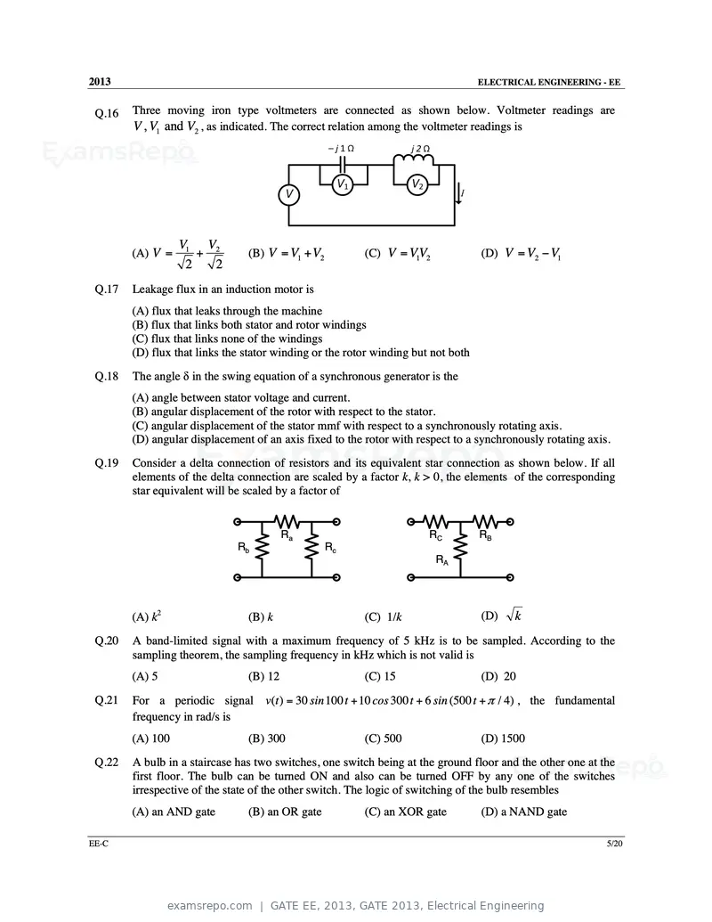
Text of page 40
2013                                                                               ELECTRICAL ENGINEERING - EE


 Q.16   Three moving iron type voltmeters are connected as shown below. Voltmeter readings are
        V , V1 and V2 , as indicated. The correct relation among the voltmeter readings is


                  V1 V2
        (A) V =      +          (B) V = V1 + V2          (C) V = 1
                                                                VV2                (D) V = V2 − V1
                   2   2
 Q.17   Leakage flux in an induction motor is
        (A) flux that leaks through the machine
        (B) flux that links both stator and rotor windings
        (C) flux that links none of the windings
        (D) flux that links the stator winding or the rotor winding but not both
 Q.18   The angle δ in the swing equation of a synchronous generator is the
        (A) angle between stator voltage and current.
        (B) angular displacement of the rotor with respect to the stator.
        (C) angular displacement of the stator mmf with respect to a synchronously rotating axis.
        (D) angular displacement of an axis fixed to the rotor with respect to a synchronously rotating axis.
 Q.19   Consider a delta connection of resistors and its equivalent star connection as shown below. If all
        elements of the delta connection are scaled by a factor k, k > 0, the elements of the corresponding
        star equivalent will be scaled by a factor of


                                         Ra                            RC          RB
                              Rb                  Rc
                                                                        RA


        (A) k2                  (B) k                    (C) 1/k                   (D)    k
 Q.20   A band-limited signal with a maximum frequency of 5 kHz is to be sampled. According to the
        sampling theorem, the sampling frequency in kHz which is not valid is
        (A) 5                   (B) 12                   (C) 15                    (D) 20
 Q.21   For a periodic signal v(t ) = 30 sin 100 t + 10 cos 300 t + 6 sin (500 t + π / 4) , the fundamental
        frequency in rad/s is
        (A) 100                 (B) 300                  (C) 500                   (D) 1500
 Q.22   A bulb in a staircase has two switches, one switch being at the ground floor and the other one at the
        first floor. The bulb can be turned ON and also can be turned OFF by any one of the switches
        irrespective of the state of the other switch. The logic of switching of the bulb resembles
        (A) an AND gate         (B) an OR gate           (C) an XOR gate           (D) a NAND gate

EE-C                                                                                                        5/20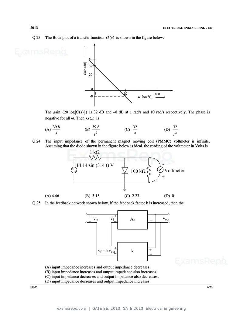
Text of page 41
2013                                                                                 ELECTRICAL ENGINEERING - EE


 Q.23   The Bode plot of a transfer function G (s ) is shown in the figure below.


                                  40

                                  32

                                  20


                                      0
                                          1             10                     100
                                   ‐8                              ω (rad/s)


        The gain (20 log G ( s ) ) is 32 dB and –8 dB at 1 rad/s and 10 rad/s respectively. The phase is
        negative for all ω. Then G (s) is

              39.8                    39.8                    32                           32
        (A)                     (B)                     (C)                          (D)
               s                          s2                   s                           s2
 Q.24   The input impedance of the permanent magnet moving coil (PMMC) voltmeter is infinite.
        Assuming that the diode shown in the figure below is ideal, the reading of the voltmeter in Volts is


        (A) 4.46                (B) 3.15                (C) 2.23                     (D) 0
 Q.25   In the feedback network shown below, if the feedback factor k is increased, then the


        (A) input impedance increases and output impedance decreases.
        (B) input impedance increases and output impedance also increases.
        (C) input impedance decreases and output impedance also decreases.
        (D) input impedance decreases and output impedance increases.
EE-C                                                                                                         6/20
Text of page 42
2013 ELECTRICAL ENGINEERING - EE
Q.26 to Q.55 carry two marks each.
1 1
Q.26 A matrix has eigenvalues –1 and –2. The corresponding eigenvectors are and
−1 − 2
respectively. The matrix is
1 1 1 2 − 1 0 0 1
(A) (B) (C) (D)
− 1 − 2 − 2 − 4 0 − 2 − 2 − 3
z2 − 4
Q.27
∫ z 2 + 4 dz evaluated anticlockwise around the circle z − i = 2 , where i = −1 , is
(A) −4π (B) 0 (C) 2 + π (D) 2 + 2i
Q.28 A dielectric slab with 500 mm × 500 mm cross-section is 0.4 m long. The slab is subjected to a uniform
electric field of E = 6 a x + 8 a y kV/mm. The relative permittivity of the dielectric material is equal to
2. The value of constant ε 0 is 8.85 × 10⁻¹² F/m. The energy stored in the dielectric in Joules is
(A) 8.85 × 10⁻¹¹ (B) 8.85 × 10⁻⁵ (C) 88.5 (D) 885
Q.29 For a power system network with n nodes, Z33 of its bus impedance matrix is j0.5 per unit. The
voltage at node 3 is 1.3 ∠–10° per unit. If a capacitor having reactance of –j3.5 per unit is now
added to the network between node 3 and the reference node, the current drawn by the capacitor per
unit is
(A) 0.325 ∠–100° (B) 0.325 ∠80° (C) 0.371 ∠–100° (D) 0.433 ∠80°
Q.30 The separately excited dc motor in the figure below has a rated armature current of 20 A and a rated
armature voltage of 150 V. An ideal chopper switching at 5 kHz is used to control the armature
voltage. If La= 0.1 mH, Ra= 1 Ω, neglecting armature reaction, the duty ratio of the chopper to
obtain 50% of the rated torque at the rated speed and the rated field current is
200 V La ,Ra
(A) 0.4 (B) 0.5 (C) 0.6 (D) 0.7
EE-C 7/20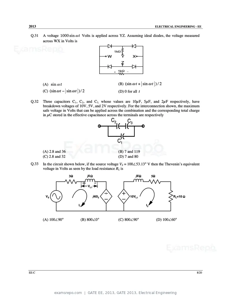
Text of page 43
2013                                                                                   ELECTRICAL ENGINEERING - EE


 Q.31   A voltage 1000 sin ω t Volts is applied across YZ. Assuming ideal diodes, the voltage measured
        across WX in Volts is

                                                         1kΩ
                                                     W         Y        X
                                                               Z

                                                         +   1kΩ   _


        (A) sin ω t                                          (B) (sin ω t + sin ω t ) / 2
        (C) (sin ω t − sin ω t ) / 2                         (D) 0 for all t

 Q.32   Three capacitors C1, C2, and C3, whose values are 10µF, 5µF, and 2µF respectively, have
        breakdown voltages of 10V, 5V, and 2V respectively. For the interconnection shown, the maximum
        safe voltage in Volts that can be applied across the combination and the corresponding total charge
        in µC stored in the effective capacitance across the terminals are respectively
                                                     C2            C3


                                                             C1
        (A) 2.8 and 36                                       (B) 7 and 119
        (C) 2.8 and 32                                       (D) 7 and 80
 Q.33   In the circuit shown below, if the source voltage VS = 100∠53.13° V then the Thevenin’s equivalent
        voltage in Volts as seen by the load resistance RL is
                         3Ω            j4 Ω                               j6 Ω        5Ω


                                       VL1


         VS                                  j40I2                     10VL1                        RL=10 Ω

                                I1                                               I2


        (A) 100∠90°              (B) 800∠0°                  (C) 800∠90°                   (D) 100∠60°


EE-C                                                                                                           8/20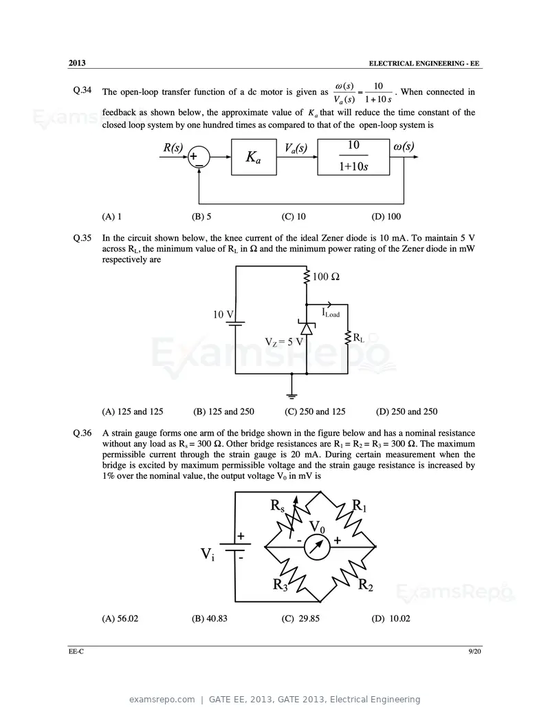
Text of page 44
2013                                                                               ELECTRICAL ENGINEERING - EE


                                                                       ω (s)     10
 Q.34   The open-loop transfer function of a dc motor is given as              =       . When connected in
                                                                    V a ( s ) 1 + 10 s
        feedback as shown below, the approximate value of K a that will reduce the time constant of the
        closed loop system by one hundred times as compared to that of the open-loop system is

                          R(s)                         Va(s)                 10         ω(s)
                                 +_              Ka
                                                                        1+10s


        (A) 1                    (B) 5                 (C) 10                      (D) 100

 Q.35   In the circuit shown below, the knee current of the ideal Zener diode is 10 mA. To maintain 5 V
        across RL, the minimum value of RL in Ω and the minimum power rating of the Zener diode in mW
        respectively are


        (A) 125 and 125          (B) 125 and 250           (C) 250 and 125          (D) 250 and 250

 Q.36   A strain gauge forms one arm of the bridge shown in the figure below and has a nominal resistance
        without any load as Rs = 300 Ω. Other bridge resistances are R1 = R2 = R3 = 300 Ω. The maximum
        permissible current through the strain gauge is 20 mA. During certain measurement when the
        bridge is excited by maximum permissible voltage and the strain gauge resistance is increased by
        1% over the nominal value, the output voltage V0 in mV is


                                                      Rs                     R1
                                                                 V0
                                             +               ‐         +
                                   Vi        ‐
                                                      R3                       R2

        (A) 56.02                (B) 40.83             (C) 29.85                   (D) 10.02


EE-C                                                                                                       9/20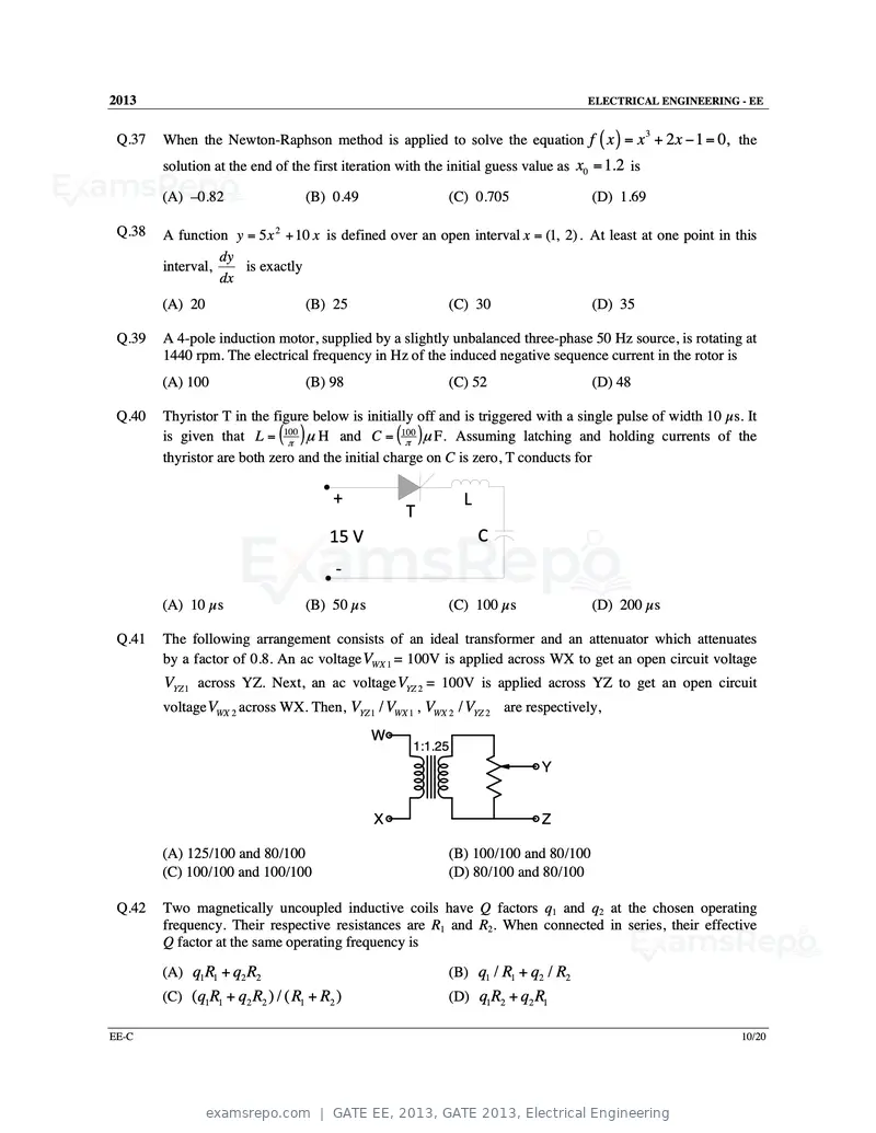
Text of page 45
2013                                                                                ELECTRICAL ENGINEERING - EE


        When the Newton-Raphson method is applied to solve the equation f ( x ) = x + 2 x − 1 = 0, the
                                                                                                 3
 Q.37
        solution at the end of the first iteration with the initial guess value as x0 = 1.2 is

        (A) –0.82                 (B) 0.49                 (C) 0.705                 (D) 1.69

 Q.38   A function y = 5 x 2 + 10 x is defined over an open interval x = (1, 2) . At least at one point in this
                  dy
        interval,    is exactly
                  dx
        (A) 20                    (B) 25                   (C) 30                    (D) 35

 Q.39   A 4-pole induction motor, supplied by a slightly unbalanced three-phase 50 Hz source, is rotating at
        1440 rpm. The electrical frequency in Hz of the induced negative sequence current in the rotor is
        (A) 100                   (B) 98                   (C) 52                    (D) 48

 Q.40   Thyristor T in the figure below is initially off and is triggered with a single pulse of width 10 µs. It
        is given that L = (100π
                                ) µ H and C = (100π )µ F. Assuming latching and holding currents of the
        thyristor are both zero and the initial charge on C is zero, T conducts for

                                       +                      L
                                                   T
                                      15 V                        C
                                       ‐
        (A) 10 µs                 (B) 50 µs                (C) 100 µs                (D) 200 µs

 Q.41   The following arrangement consists of an ideal transformer and an attenuator which attenuates
        by a factor of 0.8. An ac voltage VWX 1 = 100V is applied across WX to get an open circuit voltage
        VYZ 1 across YZ. Next, an ac voltage VYZ 2 = 100V is applied across YZ to get an open circuit
        voltage VWX 2 across WX. Then, VYZ 1 / VWX 1 , VWX 2 / VYZ 2 are respectively,
                                              W
                                                     1:1.25
                                                                            Y


                                              X                             Z

        (A) 125/100 and 80/100                             (B) 100/100 and 80/100
        (C) 100/100 and 100/100                            (D) 80/100 and 80/100

 Q.42   Two magnetically uncoupled inductive coils have Q factors q1 and q2 at the chosen operating
        frequency. Their respective resistances are R1 and R2. When connected in series, their effective
        Q factor at the same operating frequency is

        (A) q1 R1 + q2 R2                                  (B) q1 / R1 + q2 / R2
        (C) (q1R1 + q2 R2 ) / ( R1 + R2 )                  (D) q1R2 + q2 R1

EE-C                                                                                                         10/20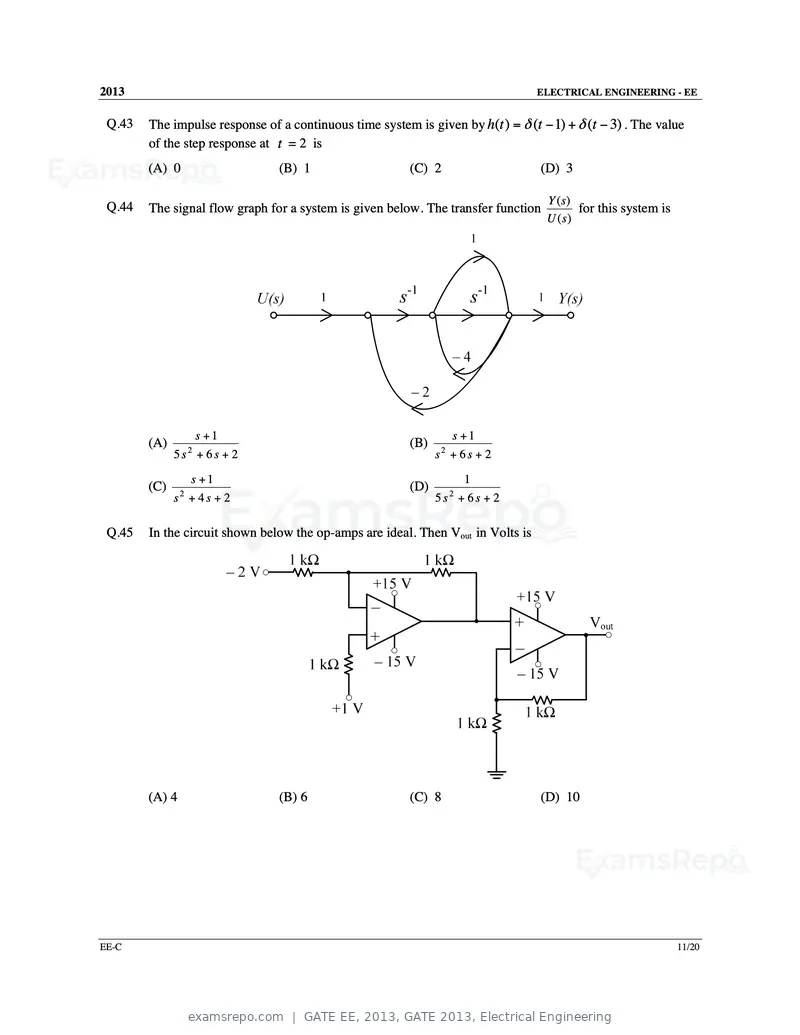
Text of page 46
2013                                                                              ELECTRICAL ENGINEERING - EE


 Q.43   The impulse response of a continuous time system is given by h(t ) = δ (t − 1) + δ (t − 3) . The value
        of the step response at t = 2 is
        (A) 0                   (B) 1                    (C) 2                    (D) 3

                                                                                   Y (s)
 Q.44   The signal flow graph for a system is given below. The transfer function          for this system is
                                                                                   U ( s)


                  s +1                                            s +1
        (A)                                              (B)
              5s2 + 6s + 2                                     s2 + 6 s + 2

                 s +1                                                1
        (C)                                              (D)
              s2 + 4 s + 2                                     5s2 + 6s + 2

 Q.45   In the circuit shown below the op-amps are ideal. Then Vout in Volts is


        (A) 4                   (B) 6                    (C) 8                    (D) 10


EE-C                                                                                                           11/20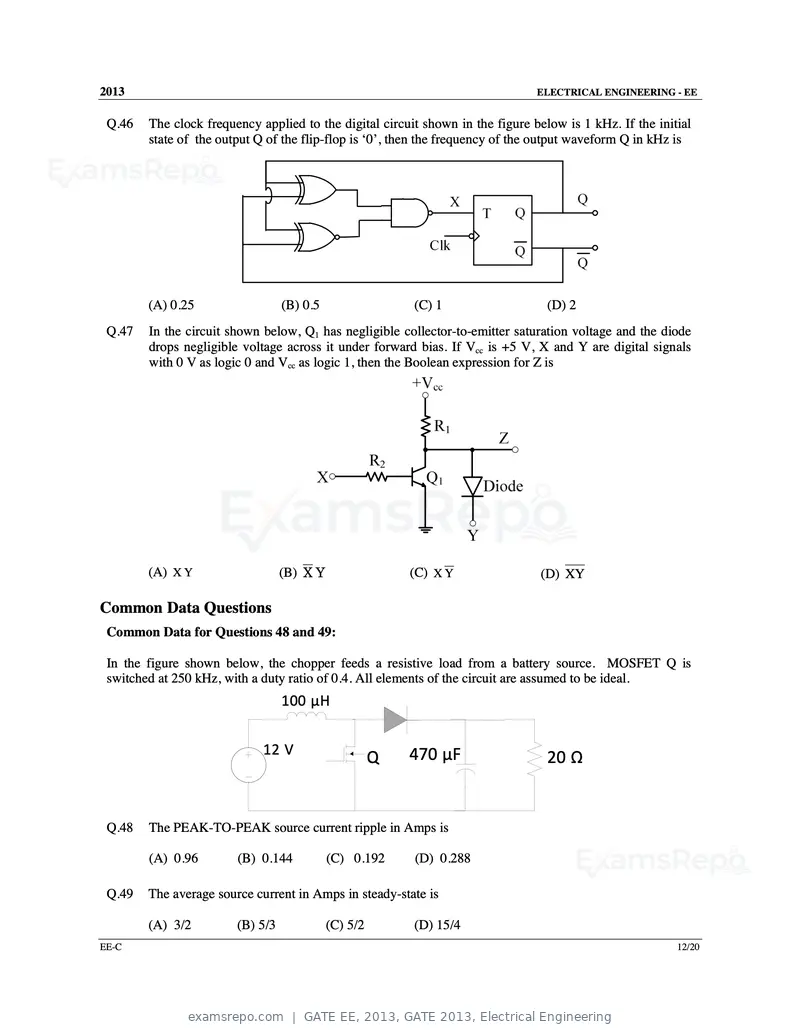
Text of page 47
2013                                                                            ELECTRICAL ENGINEERING - EE


 Q.46   The clock frequency applied to the digital circuit shown in the figure below is 1 kHz. If the initial
        state of the output Q of the flip-flop is ‘0’, then the frequency of the output waveform Q in kHz is


        (A) 0.25                  (B) 0.5                 (C) 1                   (D) 2
 Q.47   In the circuit shown below, Q1 has negligible collector-to-emitter saturation voltage and the diode
        drops negligible voltage across it under forward bias. If Vcc is +5 V, X and Y are digital signals
        with 0 V as logic 0 and Vcc as logic 1, then the Boolean expression for Z is


        (A) X Y                   (B) X Y                 (C) X Y               (D) XY

Common Data Questions
 Common Data for Questions 48 and 49:

 In the figure shown below, the chopper feeds a resistive load from a battery source. MOSFET Q is
 switched at 250 kHz, with a duty ratio of 0.4. All elements of the circuit are assumed to be ideal.
                                  100 µH


                             12 V                         470 µF
                                                      Q                           20 Ω


 Q.48   The PEAK-TO-PEAK source current ripple in Amps is

        (A) 0.96        (B) 0.144           (C) 0.192     (D) 0.288

 Q.49   The average source current in Amps in steady-state is

        (A) 3/2         (B) 5/3             (C) 5/2       (D) 15/4
EE-C                                                                                                      12/20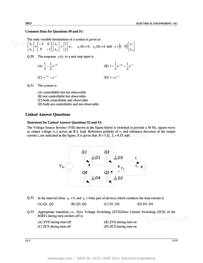
Text of page 48
2013 ELECTRICAL ENGINEERING - EE
Common Data for Questions 50 and 51:
The state variable formulation of a system is given as
x&1 − 2 0 x1 1 x1
x& = 0 − 1 x + 1 u , x1 (0) = 0, x 2 (0) = 0 and y = [1 0] x
2 2 2
Q.50 The response y (t ) to a unit step input is
1 1 −2 t 1 −2 t 1 − t
(A) − e (B) 1 − e − e
2 2 2 2
(C) e −2 t − e − t (D) 1 − e − t
Q.51 The system is
(A) controllable but not observable
(B) not controllable but observable
(C) both controllable and observable
(D) both not controllable and not observable
Linked Answer Questions
Statement for Linked Answer Questions 52 and 53:
The Voltage Source Inverter (VSI) shown in the figure below is switched to provide a 50 Hz, square-wave
ac output voltage (vo) across an R-L load. Reference polarity of vo and reference direction of the output
current io are indicated in the figure. It is given that R = 3 Ω , L = 9.55 mH .
Q1 Q3
D1 D3 L
V dc + vo io R
Q4 Q2 ‐
D4 D2
Q.52 In the interval when v 0 < 0 and i0 > 0 the pair of devices which conducts the load current is
(A) Q1, Q2 (B) Q3, Q4 (C) D1, D2 (D) D3, D4
Q.53 Appropriate transition i.e., Zero Voltage Switching (ZVS)/Zero Current Switching (ZCS) of the
IGBTs during turn-on/turn-off is
(A) ZVS during turn-off (B) ZVS during turn-on
(C) ZCS during turn-off (D) ZCS during turn-on
EE-C 13/20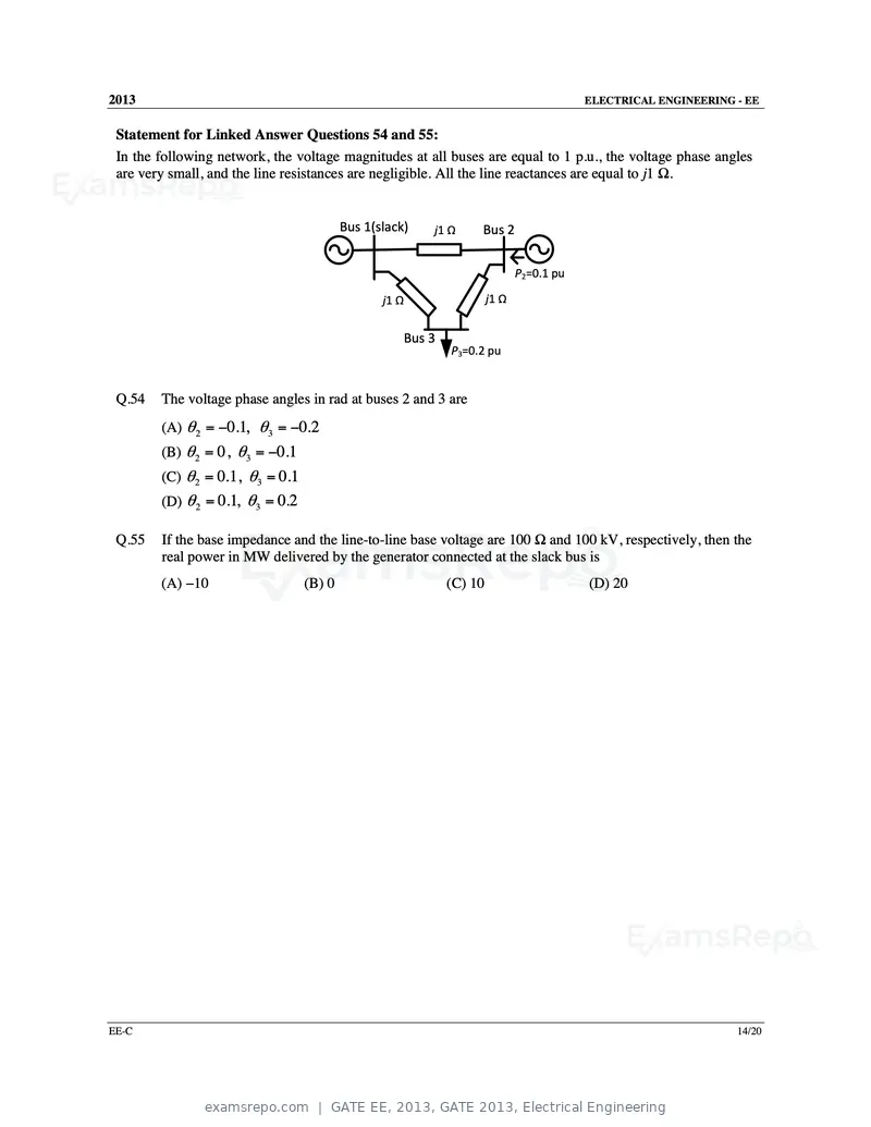
Text of page 49
2013                                                                                        ELECTRICAL ENGINEERING - EE


 Statement for Linked Answer Questions 54 and 55:
 In the following network, the voltage magnitudes at all buses are equal to 1 p.u., the voltage phase angles
 are very small, and the line resistances are negligible. All the line reactances are equal to j1 Ω.


                                          Bus 1(slack)      j1 Ω     Bus 2

                                                                                P2=0.1 pu

                                                 j1 Ω                    j1 Ω


                                                        Bus 3
                                                                P3=0.2 pu


 Q.54   The voltage phase angles in rad at buses 2 and 3 are
        (A) θ 2 = −0.1, θ3 = −0.2
        (B) θ 2 = 0, θ3 = −0.1
        (C) θ 2 = 0.1, θ3 = 0.1
        (D) θ 2 = 0.1, θ3 = 0.2

 Q.55   If the base impedance and the line-to-line base voltage are 100 Ω and 100 kV, respectively, then the
        real power in MW delivered by the generator connected at the slack bus is
        (A) −10                   (B) 0                         (C) 10                      (D) 20


EE-C                                                                                                               14/20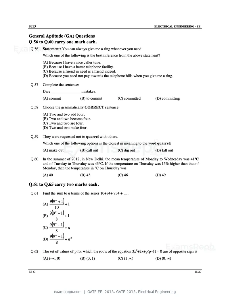
Text of page 50
2013                                                                            ELECTRICAL ENGINEERING - EE


General Aptitude (GA) Questions
Q.56 to Q.60 carry one mark each.
 Q.56   Statement: You can always give me a ring whenever you need.
        Which one of the following is the best inference from the above statement?
        (A) Because I have a nice caller tune.
        (B) Because I have a better telephone facility.
        (C) Because a friend in need is a friend indeed.
        (D) Because you need not pay towards the telephone bills when you give me a ring.

 Q.57   Complete the sentence:
        Dare _______________ mistakes.
        (A) commit               (B) to commit           (C) committed          (D) committing

 Q.58   Choose the grammatically CORRECT sentence:
        (A) Two and two add four.
        (B) Two and two become four.
        (C) Two and two are four.
        (D) Two and two make four.

 Q.59   They were requested not to quarrel with others.
        Which one of the following options is the closest in meaning to the word quarrel?
        (A) make out             (B) call out            (C) dig out            (D) fall out

 Q.60   In the summer of 2012, in New Delhi, the mean temperature of Monday to Wednesday was 41°C
        and of Tuesday to Thursday was 43°C. If the temperature on Thursday was 15% higher than that of
        Monday, then the temperature in °C on Thursday was
        (A) 40                   (B) 43                  (C) 46                 (D) 49

Q.61 to Q.65 carry two marks each.
 Q.61   Find the sum to n terms of the series 10+84+ 734 + .....

        (A)
              (
            9 9n + 1  )
                     +1
               10
        (B)
              (
            9 9n − 1  )
                     +1
               8
        (C)
              (
            9 9n −1   )
                     +n
               8
        (D)
              (
            9 9n − 1  )
                     + n2
                8

 Q.62   The set of values of p for which the roots of the equation 3x2+2x+p(p–1) = 0 are of opposite sign is
        (A) (–∞, 0)              (B) (0, 1)              (C) (1, ∞)             (D) (0, ∞)


EE-C                                                                                                      15/20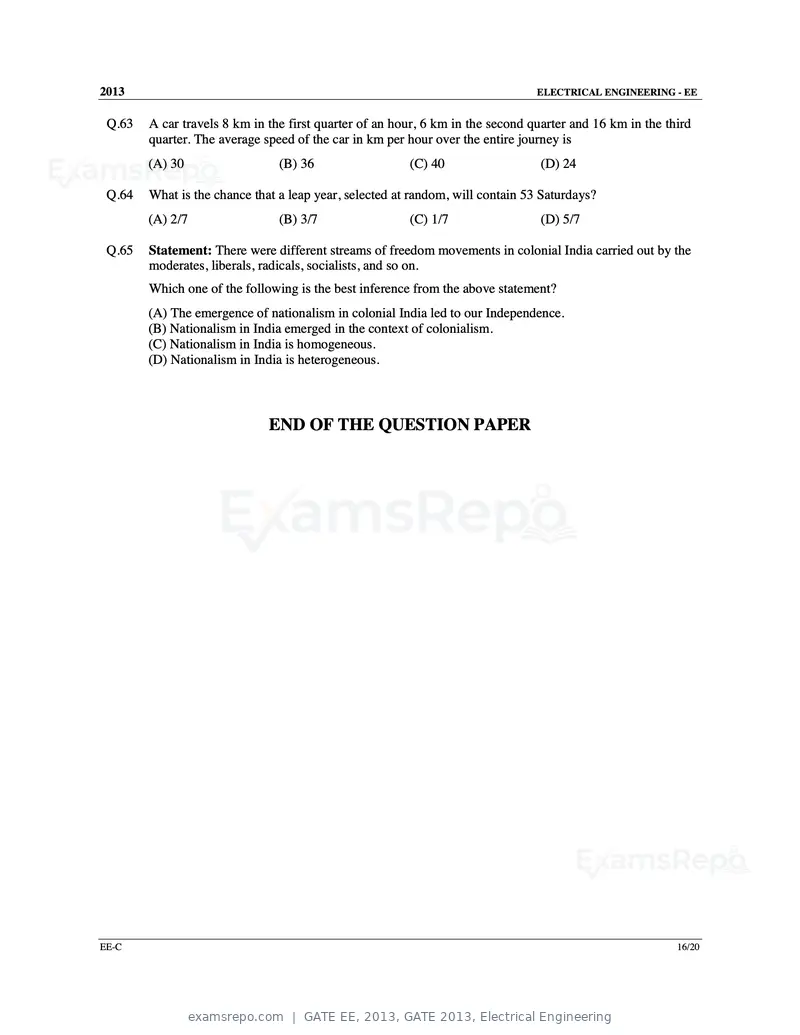
Text of page 51
2013                                                                            ELECTRICAL ENGINEERING - EE


 Q.63   A car travels 8 km in the first quarter of an hour, 6 km in the second quarter and 16 km in the third
        quarter. The average speed of the car in km per hour over the entire journey is
        (A) 30                  (B) 36                  (C) 40                  (D) 24

 Q.64   What is the chance that a leap year, selected at random, will contain 53 Saturdays?
        (A) 2/7                 (B) 3/7                 (C) 1/7                 (D) 5/7

 Q.65   Statement: There were different streams of freedom movements in colonial India carried out by the
        moderates, liberals, radicals, socialists, and so on.
        Which one of the following is the best inference from the above statement?
        (A) The emergence of nationalism in colonial India led to our Independence.
        (B) Nationalism in India emerged in the context of colonialism.
        (C) Nationalism in India is homogeneous.
        (D) Nationalism in India is heterogeneous.


                              END OF THE QUESTION PAPER


EE-C                                                                                                      16/20
Text of page 52
SESSION - 4
Text of page 53
2013                                                                      Question Booklet Code
                                                                                                         D
                               EE : ELECTRICAL ENGINEERING
Duration: Three Hours                                                                     Maximum Marks: 100

Read the following instructions carefully.

    1. Do not open the seal of the Question Booklet until you are asked to do so by the invigilator.
    2. Take out the Optical Response Sheet (ORS) from this Question Booklet without breaking the seal
        and read the instructions printed on the ORS carefully. If you find that either:
        a. The Question Booklet Code printed at the right hand top corner of this page does not match with
             the Question Booklet Code at the right hand top corner of the ORS or
        b. The Question Paper Code preceding the Registration number on the ORS is not EE,
       then exchange the booklet immediately with a new sealed Question Booklet.
    3. On the right half hand side of the ORS, using ONLY a black ink ballpoint pen, (i) darken the
       appropriate bubble under each digit of your registration number and (ii) write your registration number,
       your name and name of the examination centre and put your signature at the specified location.
    4. This Question Booklet contains 20 pages including blank pages for rough work. After you are
       permitted to open the seal, check all pages and report discrepancies, if any, to the invigilator.
    5. There are a total of 65 questions carrying 100 marks. All these questions are of objective type. Each
       question has only one correct answer. Questions must be answered on the left hand side of the ORS
       by darkening the appropriate bubble (marked A, B, C, D) using ONLY a black ink ballpoint pen
       against the question number. For each question darken the bubble of the correct answer. More
       than one answer bubbled against a question will be treated as an incorrect response.
    6. Since bubbles darkened by the black ink ballpoint pen cannot be erased, candidates should darken the
       bubbles in the ORS very carefully.
    7. Questions Q.1 – Q.25 carry 1 mark each. Questions Q.26 – Q.55 carry 2 marks each. The 2 marks
       questions include two pairs of common data questions and two pairs of linked answer questions. The
       answer to the second question of the linked answer questions depends on the answer to the first
       question of the pair. If the first question in the linked pair is wrongly answered or is not attempted,
       then the answer to the second question in the pair will not be evaluated.
    8. Questions Q.56 – Q.65 belong to General Aptitude (GA) section and carry a total of 15 marks.
       Questions Q.56 – Q.60 carry 1 mark each, and questions Q.61 – Q.65 carry 2 marks each.
    9. Questions not attempted will result in zero mark and wrong answers will result in NEGATIVE
       marks. For all 1 mark questions, ⅓ mark will be deducted for each wrong answer. For all 2 marks
       questions, ⅔ mark will be deducted for each wrong answer. However, in the case of the linked
       answer question pair, there will be negative marks only for wrong answer to the first question and no
       negative marks for wrong answer to the second question.
    10. Calculator is allowed whereas charts, graph sheets or tables are NOT allowed in the examination hall.
    11. Rough work can be done on the Question Booklet itself. Blank pages are provided at the end of the
        Question Booklet for rough work.
    12. Before the start of the examination, write your name and registration number in the space provided
        below using a black ink ballpoint pen.

           Name

           Registration Number         EE

EE-D                                                                                                       1/20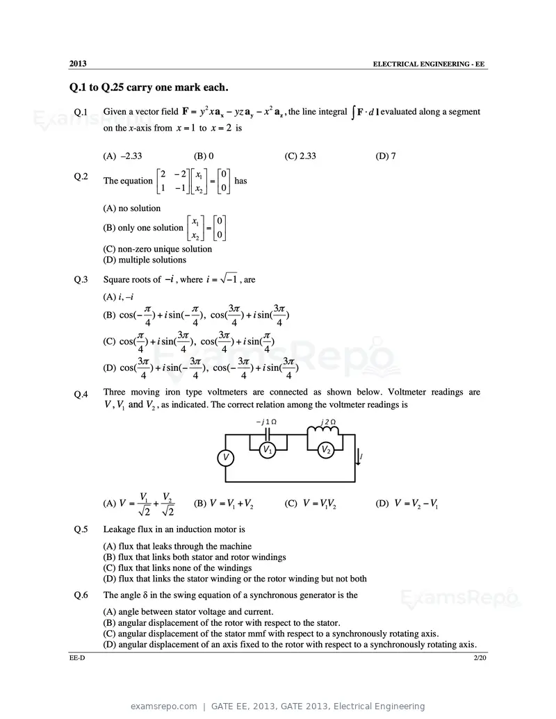
Text of page 54
2013 ELECTRICAL ENGINEERING - EE
Q.1 to Q.25 carry one mark each.
Given a vector field F = y x a x − yz a y − x a z , the line integral ∫ F ⋅ d l evaluated along a segment
2 2
Q.1
on the x-axis from x = 1 to x = 2 is
(A) –2.33 (B) 0 (C) 2.33 (D) 7
Q.2 2 − 2 x1 0
The equation = has
1 − 1 x2 0
(A) no solution
x 0
(B) only one solution 1 =
x2 0
(C) non-zero unique solution
(D) multiple solutions
Q.3 Square roots of −i , where i = −1 , are
(A) i, –i
π π 3π 3π
(B) cos( − ) + i sin( − ), cos( ) + i sin( )
4 4 4 4
π 3π 3π π
(C) cos( ) + i sin( ), cos( ) + i sin( )
4 4 4 4
3π 3π 3π 3π
(D) cos( ) + i sin( − ), cos( − ) + i sin( )
4 4 4 4
Q.4 Three moving iron type voltmeters are connected as shown below. Voltmeter readings are
V , V1 and V2 , as indicated. The correct relation among the voltmeter readings is
V1 V2
(A) V = + (B) V = V1 + V2 (C) V = VV
1 2 (D) V = V2 − V1
2 2
Q.5 Leakage flux in an induction motor is
(A) flux that leaks through the machine
(B) flux that links both stator and rotor windings
(C) flux that links none of the windings
(D) flux that links the stator winding or the rotor winding but not both
Q.6 The angle δ in the swing equation of a synchronous generator is the
(A) angle between stator voltage and current.
(B) angular displacement of the rotor with respect to the stator.
(C) angular displacement of the stator mmf with respect to a synchronously rotating axis.
(D) angular displacement of an axis fixed to the rotor with respect to a synchronously rotating axis.
EE-D 2/20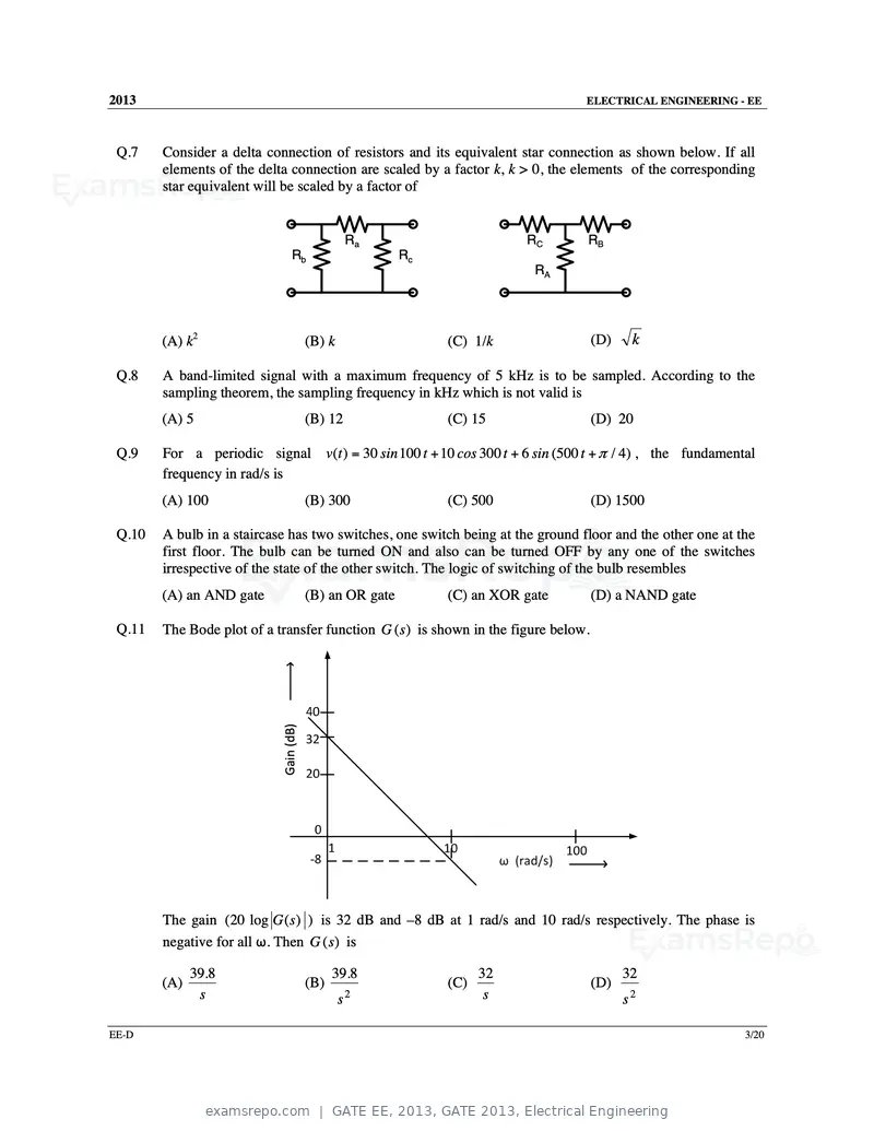
Text of page 55
2013                                                                            ELECTRICAL ENGINEERING - EE


 Q.7    Consider a delta connection of resistors and its equivalent star connection as shown below. If all
        elements of the delta connection are scaled by a factor k, k > 0, the elements of the corresponding
        star equivalent will be scaled by a factor of


                                                    Ra                   RC     RB
                                 Rb                      Rc
                                                                           RA


        (A) k2                          (B) k                 (C) 1/k               (D)    k

 Q.8    A band-limited signal with a maximum frequency of 5 kHz is to be sampled. According to the
        sampling theorem, the sampling frequency in kHz which is not valid is
        (A) 5                           (B) 12                (C) 15                (D) 20

 Q.9    For a periodic signal v(t ) = 30 sin 100 t + 10 cos 300 t + 6 sin (500 t + π / 4) , the fundamental
        frequency in rad/s is
        (A) 100                         (B) 300               (C) 500               (D) 1500

 Q.10   A bulb in a staircase has two switches, one switch being at the ground floor and the other one at the
        first floor. The bulb can be turned ON and also can be turned OFF by any one of the switches
        irrespective of the state of the other switch. The logic of switching of the bulb resembles
        (A) an AND gate                 (B) an OR gate        (C) an XOR gate       (D) a NAND gate

 Q.11   The Bode plot of a transfer function G (s ) is shown in the figure below.


                            Gain (dB)


        The gain (20 log G ( s ) ) is 32 dB and –8 dB at 1 rad/s and 10 rad/s respectively. The phase is
        negative for all ω. Then G (s) is

              39.8                            39.8                  32                    32
        (A)                             (B)                   (C)                   (D)
               s                                s   2                s                    s2

EE-D                                                                                                       3/20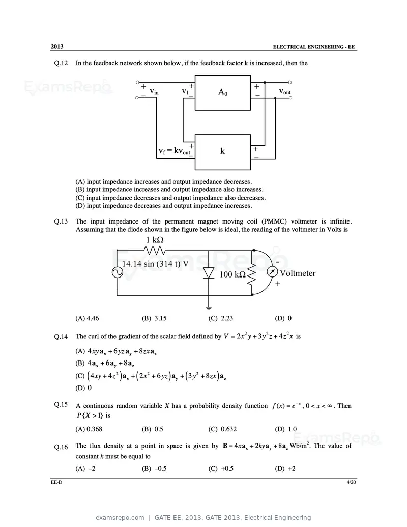
Text of page 56
2013                                                                                  ELECTRICAL ENGINEERING - EE


 Q.12   In the feedback network shown below, if the feedback factor k is increased, then the


                                        + v                    +               +         vout
                                              in          v1          A0        –
                                        –                      –


                                                   vf = kvout+           k     +
                                                               –               –


        (A) input impedance increases and output impedance decreases.
        (B) input impedance increases and output impedance also increases.
        (C) input impedance decreases and output impedance also decreases.
        (D) input impedance decreases and output impedance increases.

 Q.13   The input impedance of the permanent magnet moving coil (PMMC) voltmeter is infinite.
        Assuming that the diode shown in the figure below is ideal, the reading of the voltmeter in Volts is


        (A) 4.46                        (B) 3.15                   (C) 2.23            (D) 0

 Q.14   The curl of the gradient of the scalar field defined by V = 2 x 2 y + 3 y 2 z + 4 z 2 x is

        (A) 4 xy a x + 6 yz a y + 8 zx a z
        (B) 4 a x + 6 a y + 8 a z

             (            )         (                 )    (
        (C) 4 xy + 4 z 2 a x + 2 x 2 + 6 yz a y + 3 y 2 + 8 zx a z   )
        (D) 0

 Q.15   A continuous random variable X has a probability density function f ( x) = e − x , 0 < x < ∞ . Then
        P { X > 1} is

        (A) 0.368                       (B) 0.5                    (C) 0.632           (D) 1.0

 Q.16   The flux density at a point in space is given by B = 4 x a x + 2ky a y + 8 a z Wb/m2. The value of
        constant k must be equal to
        (A) –2                          (B) –0.5                   (C) +0.5            (D) +2
EE-D                                                                                                          4/20
Text of page 57
2013                                                                                           ELECTRICAL ENGINEERING - EE


 Q.17   A single-phase transformer has no-load loss of 64 W, as obtained from an open-circuit test. When a
        short-circuit test is performed on it with 90% of the rated currents flowing in its both LV and HV
        windings, the measured loss is 81 W. The transformer has maximum efficiency when operated at
        (A) 50.0% of the rated current.
        (B) 64.0% of the rated current.
        (C) 80.0% of the rated current.
        (D) 88.8% of the rated current.


 Q.18   A single-phase load is supplied by a single-phase voltage source. If the current flowing from the
        load to the source is 10∠ − 1500 A and if the voltage at the load terminals is 100∠600 V, then the
        (A) load absorbs real power and delivers reactive power.
        (B) load absorbs real power and absorbs reactive power.
        (C) load delivers real power and delivers reactive power.
        (D) load delivers real power and absorbs reactive power.


 Q.19   A source vs (t ) = V cos100π t has an internal impedance of (4 + j3) Ω. If a purely resistive load
        connected to this source has to extract the maximum power out of the source, its value in Ω should
        be
        (A) 3                     (B) 4                          (C) 5                         (D) 7


 Q.20   Two systems with impulse responses h1 (t ) and h2 (t ) are connected in cascade. Then the overall
        impulse response of the cascaded system is given by

        (A) product of h1 (t ) and h2 (t )
        (B) sum of h1 (t ) and h2 (t )
        (C) convolution of h1 (t ) and h2 (t )
        (D) subtraction of h2 (t ) from h1 (t )


 Q.21   Which one of the following statements is NOT TRUE for a continuous time causal and stable
        LTI system?
        (A) All the poles of the system must lie on the left side of the jω axis.
        (B) Zeros of the system can lie anywhere in the s-plane.
        (C) All the poles must lie within s = 1.
        (D) All the roots of the characteristic equation must be located on the left side of the jω axis.


 Q.22   The impulse response of a system is h(t ) = t u (t ) . For an input u (t − 1) , the output is

                2                        t (t − 1)                     (t − 1) 2                     t2 −1
        (A) t u (t )              (B)                u (t − 1)   (C)               u (t − 1)   (D)           u (t − 1)
             2                               2                            2                            2


EE-D                                                                                                                     5/20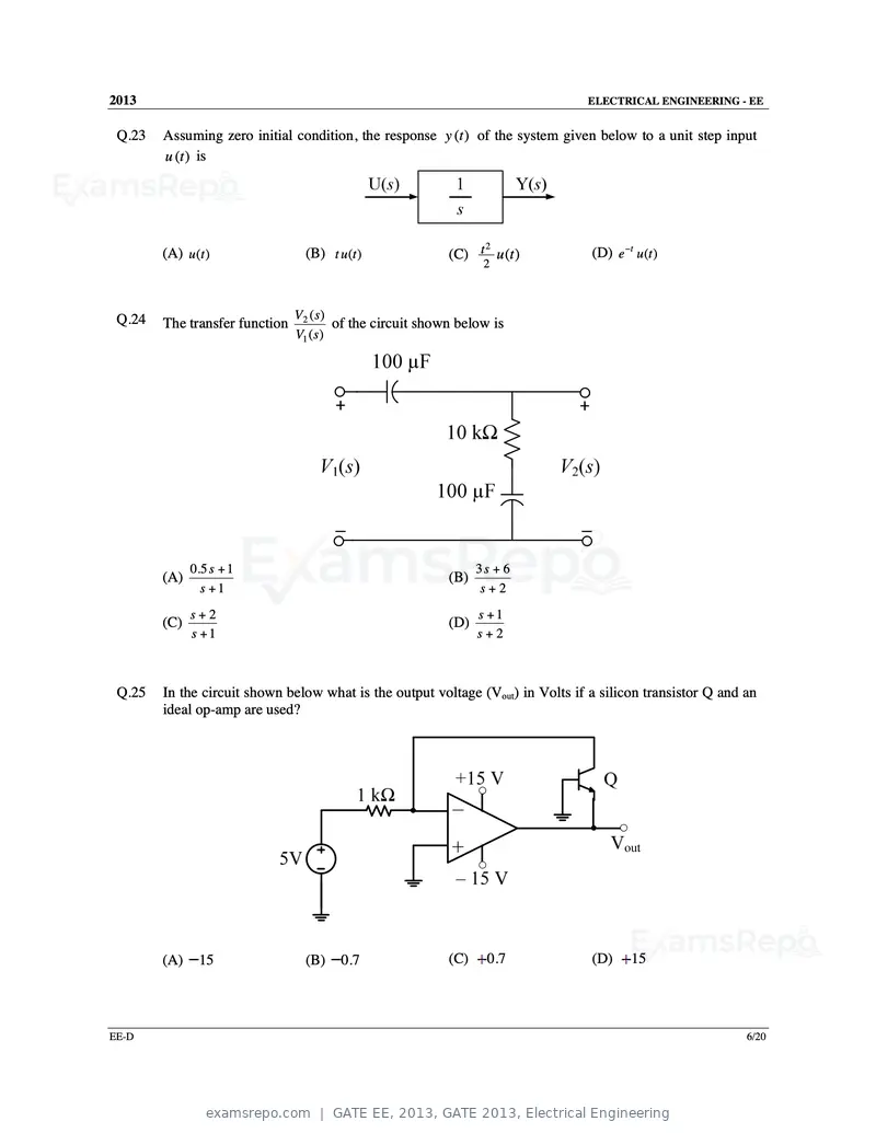
Text of page 58
2013                                                                             ELECTRICAL ENGINEERING - EE


 Q.23   Assuming zero initial condition, the response y (t ) of the system given below to a unit step input
        u (t ) is


                                                                                 (D) e −t u (t )
                                                                 2
        (A) u (t )                (B) t u (t )              (C) t u (t )
                                                                   2


 Q.24                           V2 ( s )
        The transfer function            of the circuit shown below is
                                V1 ( s )


              0.5 s + 1                                           3s + 6
        (A)                                                 (B)
                s +1                                               s+2
              s+2                                                 s +1
        (C)                                                 (D)
              s +1                                                s+2


 Q.25   In the circuit shown below what is the output voltage (Vout) in Volts if a silicon transistor Q and an
        ideal op-amp are used?


        (A)    15                 (B)    0.7                (C)     0.7          (D)     15


EE-D                                                                                                        6/20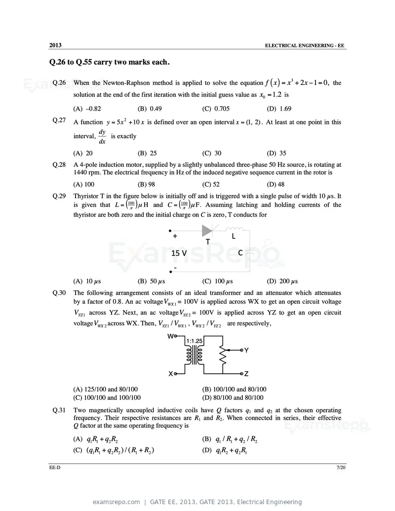
Text of page 59
2013                                                                                ELECTRICAL ENGINEERING - EE


Q.26 to Q.55 carry two marks each.

        When the Newton-Raphson method is applied to solve the equation f ( x ) = x + 2 x − 1 = 0, the
                                                                                                 3
 Q.26
        solution at the end of the first iteration with the initial guess value as x0 = 1.2 is

        (A) –0.82                 (B) 0.49                 (C) 0.705                 (D) 1.69
 Q.27   A function y = 5 x 2 + 10 x is defined over an open interval x = (1, 2) . At least at one point in this
                  dy
        interval,    is exactly
                  dx
        (A) 20                    (B) 25                   (C) 30                    (D) 35
 Q.28   A 4-pole induction motor, supplied by a slightly unbalanced three-phase 50 Hz source, is rotating at
        1440 rpm. The electrical frequency in Hz of the induced negative sequence current in the rotor is
        (A) 100                   (B) 98                   (C) 52                    (D) 48
 Q.29   Thyristor T in the figure below is initially off and is triggered with a single pulse of width 10 µs. It
        is given that L = (100π
                                ) µ H and C = (100π )µ F. Assuming latching and holding currents of the
        thyristor are both zero and the initial charge on C is zero, T conducts for


                                                  +                    L
                                                               T
                                               15 V                        C
                                                  -
        (A) 10 µs                 (B) 50 µs                (C) 100 µs                (D) 200 µs
 Q.30   The following arrangement consists of an ideal transformer and an attenuator which attenuates
        by a factor of 0.8. An ac voltage VWX 1 = 100V is applied across WX to get an open circuit voltage
        VYZ 1 across YZ. Next, an ac voltage VYZ 2 = 100V is applied across YZ to get an open circuit
        voltage VWX 2 across WX. Then, VYZ 1 / VWX 1 , VWX 2 / VYZ 2 are respectively,
                                              W
                                                      1:1.25
                                                                               Y


                                              X                                Z

        (A) 125/100 and 80/100                             (B) 100/100 and 80/100
        (C) 100/100 and 100/100                            (D) 80/100 and 80/100
 Q.31   Two magnetically uncoupled inductive coils have Q factors q1 and q2 at the chosen operating
        frequency. Their respective resistances are R1 and R2. When connected in series, their effective
        Q factor at the same operating frequency is

        (A) q1 R1 + q2 R2                                  (B) q1 / R1 + q2 / R2
        (C) (q1R1 + q2 R2 ) / ( R1 + R2 )                  (D) q1R2 + q2 R1

EE-D                                                                                                          7/20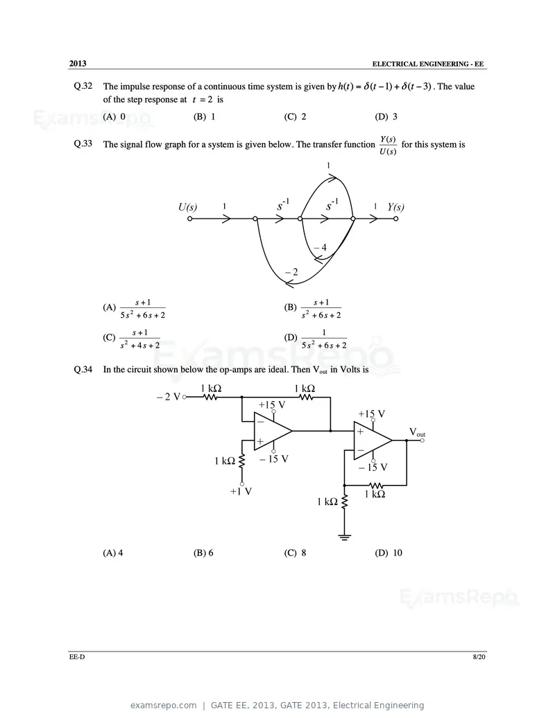
Text of page 60
2013                                                                              ELECTRICAL ENGINEERING - EE


 Q.32   The impulse response of a continuous time system is given by h(t ) = δ (t − 1) + δ (t − 3) . The value
        of the step response at t = 2 is
        (A) 0                   (B) 1                    (C) 2                    (D) 3

                                                                                   Y (s)
 Q.33   The signal flow graph for a system is given below. The transfer function          for this system is
                                                                                   U ( s)


                  s +1                                            s +1
        (A)                                              (B)
              5s2 + 6s + 2                                     s2 + 6 s + 2

                 s +1                                                1
        (C)                                              (D)
              s2 + 4 s + 2                                     5s2 + 6s + 2

 Q.34   In the circuit shown below the op-amps are ideal. Then Vout in Volts is


        (A) 4                   (B) 6                    (C) 8                    (D) 10


EE-D                                                                                                           8/20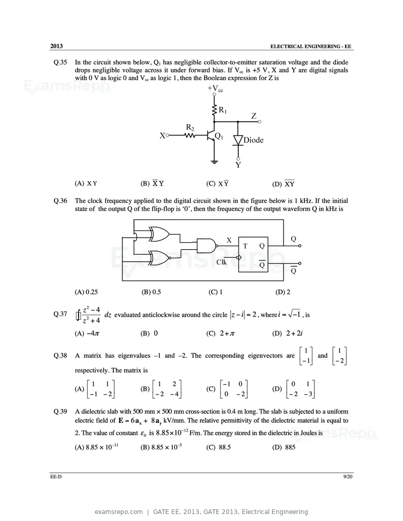
Text of page 61
2013 ELECTRICAL ENGINEERING - EE
Q.35 In the circuit shown below, Q1 has negligible collector-to-emitter saturation voltage and the diode
drops negligible voltage across it under forward bias. If Vcc is +5 V, X and Y are digital signals
with 0 V as logic 0 and Vcc as logic 1, then the Boolean expression for Z is
(A) X Y (B) X Y (C) X Y (D) XY
Q.36 The clock frequency applied to the digital circuit shown in the figure below is 1 kHz. If the initial
state of the output Q of the flip-flop is ‘0’, then the frequency of the output waveform Q in kHz is
(A) 0.25 (B) 0.5 (C) 1 (D) 2
z2 − 4
Q.37
∫ z 2 + 4 dz evaluated anticlockwise around the circle z − i = 2 , where i = −1 , is
(A) −4π (B) 0 (C) 2 + π (D) 2 + 2i
1 1
Q.38 A matrix has eigenvalues –1 and –2. The corresponding eigenvectors are and
−1
− 2
respectively. The matrix is
1 1 1 2 − 1 0 0 1
(A) (B) (C) (D)
− 1 − 2 − 2 − 4 0 − 2 − 2 − 3
Q.39 A dielectric slab with 500 mm × 500 mm cross-section is 0.4 m long. The slab is subjected to a uniform
electric field of E = 6 a x + 8 a y kV/mm. The relative permittivity of the dielectric material is equal to
2. The value of constant ε 0 is 8.85 × 10⁻¹² F/m. The energy stored in the dielectric in Joules is
(A) 8.85 × 10⁻¹¹ (B) 8.85 × 10⁻⁵ (C) 88.5 (D) 885
EE-D 9/20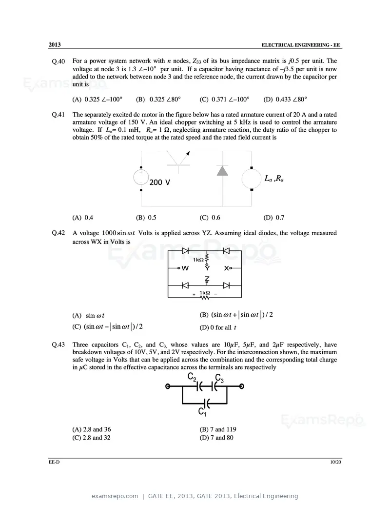
Text of page 62
2013                                                                             ELECTRICAL ENGINEERING - EE


 Q.40   For a power system network with n nodes, Z33 of its bus impedance matrix is j0.5 per unit. The
        voltage at node 3 is 1.3 ∠–10° per unit. If a capacitor having reactance of –j3.5 per unit is now
        added to the network between node 3 and the reference node, the current drawn by the capacitor per
        unit is

        (A) 0.325 ∠–100°         (B) 0.325 ∠80°           (C) 0.371 ∠–100°        (D) 0.433 ∠80°

 Q.41   The separately excited dc motor in the figure below has a rated armature current of 20 A and a rated
        armature voltage of 150 V. An ideal chopper switching at 5 kHz is used to control the armature
        voltage. If La= 0.1 mH, Ra= 1 Ω, neglecting armature reaction, the duty ratio of the chopper to
        obtain 50% of the rated torque at the rated speed and the rated field current is


                                       200 V                                      La ,Ra


        (A) 0.4                  (B) 0.5                  (C) 0.6                 (D) 0.7

 Q.42   A voltage 1000 sin ω t Volts is applied across YZ. Assuming ideal diodes, the voltage measured
        across WX in Volts is

                                                      1kΩ
                                                  W         Y        X
                                                            Z

                                                      +   1kΩ   _


        (A) sin ω t                                       (B) (sin ω t + sin ω t ) / 2
        (C) (sin ω t − sin ω t ) / 2                      (D) 0 for all t

 Q.43   Three capacitors C1, C2, and C3, whose values are 10µF, 5µF, and 2µF respectively, have
        breakdown voltages of 10V, 5V, and 2V respectively. For the interconnection shown, the maximum
        safe voltage in Volts that can be applied across the combination and the corresponding total charge
        in µC stored in the effective capacitance across the terminals are respectively
                                                   C2           C3


                                                          C1
        (A) 2.8 and 36                                    (B) 7 and 119
        (C) 2.8 and 32                                    (D) 7 and 80


EE-D                                                                                                     10/20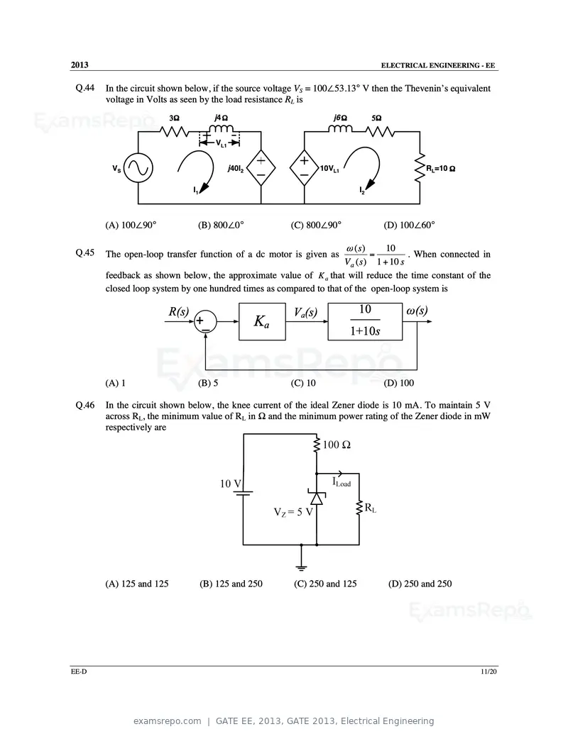
Text of page 63
2013                                                                                     ELECTRICAL ENGINEERING - EE


 Q.44   In the circuit shown below, if the source voltage VS = 100∠53.13° V then the Thevenin’s equivalent
        voltage in Volts as seen by the load resistance RL is
                          3Ω             j4 Ω                           j6 Ω         5Ω


                                         VL1


         VS                                    j40I2                 10VL1                          RL=10 Ω

                                 I1                                             I2


        (A) 100∠90°               (B) 800∠0°                (C) 800∠90°                   (D) 100∠60°

                                                                             ω (s)
                                                                                 10
 Q.45   The open-loop transfer function of a dc motor is given as                    = . When connected in
                                                                    V a ( s ) 1 + 10 s
        feedback as shown below, the approximate value of K a that will reduce the time constant of the
        closed loop system by one hundred times as compared to that of the open-loop system is

                          R(s)                              Va(s)               10             ω(s)
                                 +_                    Ka
                                                                               1+10s


        (A) 1                     (B) 5                     (C) 10                        (D) 100

 Q.46   In the circuit shown below, the knee current of the ideal Zener diode is 10 mA. To maintain 5 V
        across RL, the minimum value of RL in Ω and the minimum power rating of the Zener diode in mW
        respectively are


        (A) 125 and 125               (B) 125 and 250       (C) 250 and 125                (D) 250 and 250


EE-D                                                                                                            11/20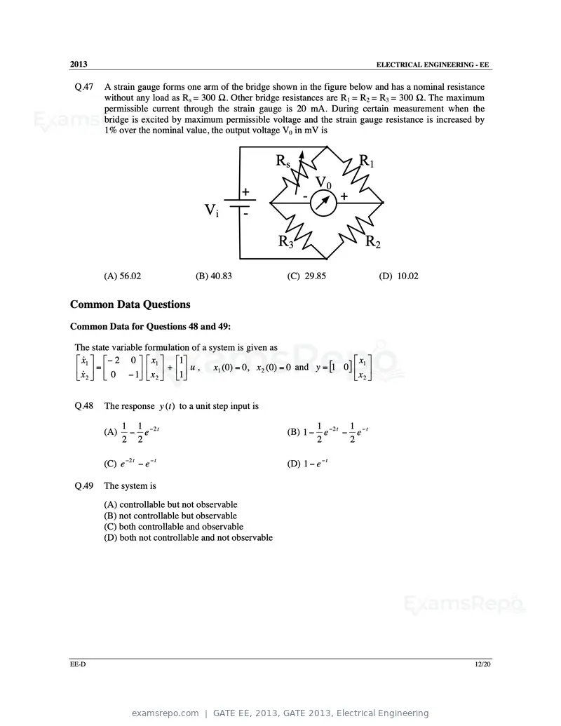
Text of page 64
2013 ELECTRICAL ENGINEERING - EE
Q.47 A strain gauge forms one arm of the bridge shown in the figure below and has a nominal resistance
without any load as Rs = 300 Ω. Other bridge resistances are R1 = R2 = R3 = 300 Ω. The maximum
permissible current through the strain gauge is 20 mA. During certain measurement when the
bridge is excited by maximum permissible voltage and the strain gauge resistance is increased by
1% over the nominal value, the output voltage V0 in mV is
Rs R1
V0
+ - +
Vi -
R3 R2
(A) 56.02 (B) 40.83 (C) 29.85 (D) 10.02
Common Data Questions
Common Data for Questions 48 and 49:
The state variable formulation of a system is given as
x&1 − 2 0 x1 1 x1
x& = 0 − 1 x + 1 u , x1 (0) = 0, x 2 (0) = 0 and y = [1 0] x
2 2 2
Q.48 The response y (t ) to a unit step input is
1 1 −2 t 1 −2 t 1 − t
(A) − e (B) 1 − e − e
2 2 2 2
(C) e −2 t − e − t (D) 1 − e − t
Q.49 The system is
(A) controllable but not observable
(B) not controllable but observable
(C) both controllable and observable
(D) both not controllable and not observable
EE-D 12/20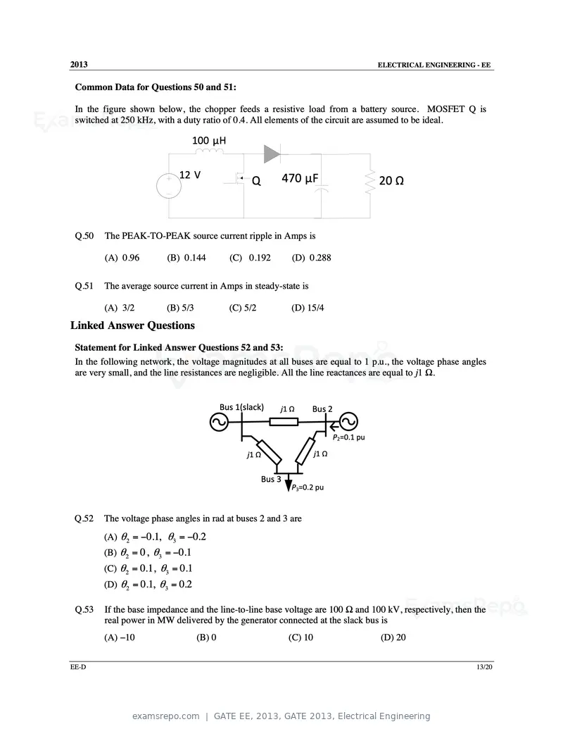
Text of page 65
2013                                                                                         ELECTRICAL ENGINEERING - EE


 Common Data for Questions 50 and 51:

 In the figure shown below, the chopper feeds a resistive load from a battery source. MOSFET Q is
 switched at 250 kHz, with a duty ratio of 0.4. All elements of the circuit are assumed to be ideal.

                                 100 µH


                            12 V                                470 µF
                                                  Q                                          20 Ω


 Q.50   The PEAK-TO-PEAK source current ripple in Amps is

        (A) 0.96        (B) 0.144           (C) 0.192            (D) 0.288

 Q.51   The average source current in Amps in steady-state is

        (A) 3/2         (B) 5/3             (C) 5/2              (D) 15/4
Linked Answer Questions
 Statement for Linked Answer Questions 52 and 53:
 In the following network, the voltage magnitudes at all buses are equal to 1 p.u., the voltage phase angles
 are very small, and the line resistances are negligible. All the line reactances are equal to j1 Ω.


                                          Bus 1(slack)      j1 Ω      Bus 2

                                                                                 P2=0.1 pu

                                                 j1 Ω                     j1 Ω


                                                        Bus 3
                                                                 P3=0.2 pu


 Q.52   The voltage phase angles in rad at buses 2 and 3 are
        (A) θ 2 = −0.1, θ3 = −0.2
        (B) θ 2 = 0, θ3 = −0.1
        (C) θ 2 = 0.1, θ3 = 0.1
        (D) θ 2 = 0.1, θ3 = 0.2

 Q.53   If the base impedance and the line-to-line base voltage are 100 Ω and 100 kV, respectively, then the
        real power in MW delivered by the generator connected at the slack bus is
        (A) −10                   (B) 0                          (C) 10                      (D) 20

EE-D                                                                                                                13/20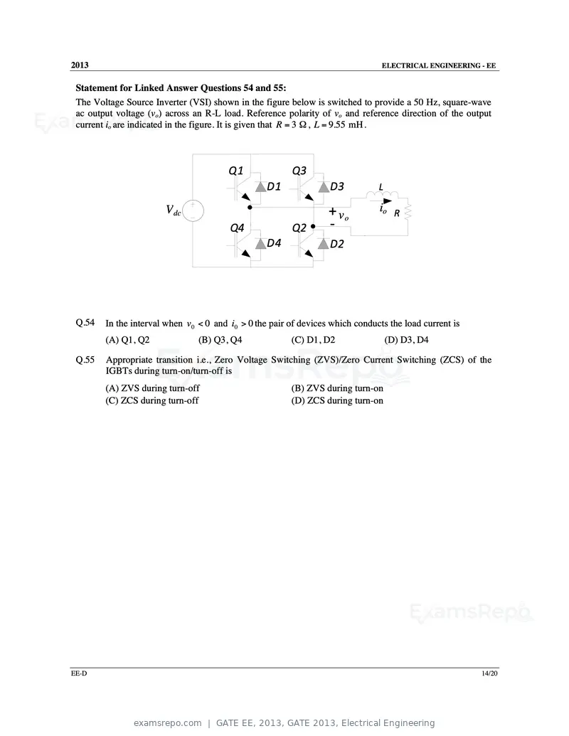
Text of page 66
2013                                                                             ELECTRICAL ENGINEERING - EE


 Statement for Linked Answer Questions 54 and 55:
 The Voltage Source Inverter (VSI) shown in the figure below is switched to provide a 50 Hz, square-wave
 ac output voltage (vo) across an R-L load. Reference polarity of vo and reference direction of the output
 current io are indicated in the figure. It is given that R = 3 Ω , L = 9.55 mH .


                                        Q1               Q3
                                                  D1               D3           L

                       V dc                                        + vo         io R
                                         Q4              Q2        -
                                                  D4               D2


 Q.54   In the interval when v 0 < 0 and i0 > 0 the pair of devices which conducts the load current is
        (A) Q1, Q2              (B) Q3, Q4               (C) D1, D2                 (D) D3, D4

 Q.55   Appropriate transition i.e., Zero Voltage Switching (ZVS)/Zero Current Switching (ZCS) of the
        IGBTs during turn-on/turn-off is
        (A) ZVS during turn-off                          (B) ZVS during turn-on
        (C) ZCS during turn-off                          (D) ZCS during turn-on


EE-D                                                                                                     14/20
Text of page 67
2013                                                                            ELECTRICAL ENGINEERING - EE


General Aptitude (GA) Questions

Q.56 to Q.60 carry one mark each.
 Q.56   Choose the grammatically CORRECT sentence:
        (A) Two and two add four.
        (B) Two and two become four.
        (C) Two and two are four.
        (D) Two and two make four.

 Q.57   Statement: You can always give me a ring whenever you need.
        Which one of the following is the best inference from the above statement?
        (A) Because I have a nice caller tune.
        (B) Because I have a better telephone facility.
        (C) Because a friend in need is a friend indeed.
        (D) Because you need not pay towards the telephone bills when you give me a ring.
 Q.58   In the summer of 2012, in New Delhi, the mean temperature of Monday to Wednesday was 41°C
        and of Tuesday to Thursday was 43°C. If the temperature on Thursday was 15% higher than that of
        Monday, then the temperature in °C on Thursday was
        (A) 40                   (B) 43                  (C) 46                  (D) 49

 Q.59   Complete the sentence:
        Dare _______________ mistakes.
        (A) commit               (B) to commit           (C) committed           (D) committing
 Q.60   They were requested not to quarrel with others.
        Which one of the following options is the closest in meaning to the word quarrel?
        (A) make out             (B) call out            (C) dig out             (D) fall out

Q.61 to Q.65 carry two marks each.

 Q.61   A car travels 8 km in the first quarter of an hour, 6 km in the second quarter and 16 km in the third
        quarter. The average speed of the car in km per hour over the entire journey is
        (A) 30                   (B) 36                  (C) 40                  (D) 24

 Q.62   Find the sum to n terms of the series 10+84+ 734 + .....

        (A)
              (
            9 9n + 1 )
                     +1
               10
        (B)
              (
            9 9n − 1 )
                     +1
               8
        (C)
              (
            9 9n −1  )
                     +n
               8
        (D)
              (
            9 9n − 1 )
                     + n2
                8
EE-D                                                                                                      15/20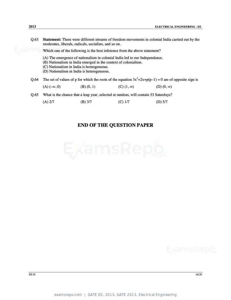
Text of page 68
2013                                                                            ELECTRICAL ENGINEERING - EE


 Q.63   Statement: There were different streams of freedom movements in colonial India carried out by the
        moderates, liberals, radicals, socialists, and so on.
        Which one of the following is the best inference from the above statement?
        (A) The emergence of nationalism in colonial India led to our Independence.
        (B) Nationalism in India emerged in the context of colonialism.
        (C) Nationalism in India is homogeneous.
        (D) Nationalism in India is heterogeneous.

 Q.64   The set of values of p for which the roots of the equation 3x2+2x+p(p–1) = 0 are of opposite sign is
        (A) (–∞, 0)             (B) (0, 1)              (C) (1, ∞)              (D) (0, ∞)

 Q.65   What is the chance that a leap year, selected at random, will contain 53 Saturdays?
        (A) 2/7                 (B) 3/7                 (C) 1/7                 (D) 5/7


                              END OF THE QUESTION PAPER


EE-D                                                                                                      16/20
Official key not published for this paper.
Page 1 of 68
Source: GATE. Question paper published by GATE.