
GATE EE 2014: Electrical Engineering Session 2
Text of page 1
SESSION - 1

Text of page 2
GATE 2014: General Instructions during Examination

   1. Total duration of the GATE examination is 180 minutes.
   2. The clock will be set at the server. The countdown timer at the top right corner of
      screen will display the remaining time available for you to complete the examination.
      When the timer reaches zero, the examination will end by itself. You need not
      terminate the examination or submit your paper.
   3. Any useful data required for your paper can be viewed by clicking on the Useful
      Common Data button that appears on the screen.
   4. Use the scribble pad provided to you for any rough work. Submit the scribble pad at
      the end of the examination.
   5. You are allowed to use a non-programmable type calculator, however, sharing of
      calculators is not allowed.
   6. The Question Palette displayed on the right side of screen will show the status of
      each question using one of the following symbols:


The Marked for Review status for a question simply indicates that you would like to look at
that question again. If a question is answered, but marked for review, then the answer will
be considered for evaluation unless the status is modified by the candidate.

Navigating to a Question :

   7. To answer a question, do the following:
         a. Click on the question number in the Question Palette to go to that question
            directly.
         b. Select an answer for a multiple choice type question by clicking on the bubble
            placed before the 4 choices, namely A, B, C and D. Use the virtual numeric
            keypad to enter a number as answer for a numerical type question.
         c. Click on Save & Next to save your answer for the current question and then go
            to the next question.
         d. Click on Mark for Review & Next to save your answer for the current question
            and also mark it for review, and then go to the next question.
Text of page 3
Caution: Note that your answer for the current question will not be saved, if you navigate
to another question directly by clicking on a question number without saving the answer to
the previous question.

You can view all the questions by clicking on the Question Paper button. This feature is
provided, so that if you want you can just see the entire question paper at a glance.

Answering a Question :

   8. Procedure for answering a multiple choice (MCQ) type question:
         a. Choose one answer from the 4 options (A,B,C,D) given below the question,
            click on the bubble placed before the chosen option.
         b. To deselect your chosen answer, click on the bubble of the chosen option again
            or click on the Clear Response button.
         c. To change your chosen answer, click on the bubble of another option.
         d. To save your answer, you MUST click on the Save & Next button.

   9. Procedure for answering a numerical answer type question:
         a. To enter a number as your answer, use the virtual numerical keypad.
         b. A fraction (e.g. -0.3 or -.3) can be entered as an answer with or without '0'
             before the decimal point. As many as four decimal points, e.g. 12.5435 or
             0.003 or -932.6711 or 12.82 can be entered.
         c. To clear your answer, click on the Clear Response button.
         d. To save your answer, you MUST click on the Save & Next button
   10. To mark a question for review, click on the Mark for Review & Next button. If an
      answer is selected (for MCQ) or entered (for numerical answer type) for a question
      that is Marked for Review, that answer will be considered in the evaluation unless
      the status is modified by the candidate.

   11. To change your answer to a question that has already been answered, first select
      that question for answering and then follow the procedure for answering that type of
      question.
   12. Note that ONLY Questions for which answers are saved or marked for review after
      answering will be considered for evaluation.


      Choosing a Section :

   13. Sections in this question paper are displayed on the top bar of the screen. Questions
      in a Section can be viewed by clicking on the name of that Section. The Section you
      are currently viewing will be highlighted.
   14. A checkbox is displayed for every optional Section, if any, in the Question Paper. To
      select the optional Section for answering, click on the checkbox for that Section.
   15. If the checkbox for an optional Section is not selected, the Save & Next button and
      the Mark for Review & Next button will NOT be enabled for that Section. You will
Text of page 4
only be able to see questions in this Section, but you will not be able to answer
      questions in the Section.
   16. After clicking the Save & Next button for the last question in a Section, you will
      automatically be taken to the first question of the next Section in sequence.
   17. You can move the mouse cursor over the name of a Section to view the answering
      status for that Section.


Changing the Optional Section :

   18. After answering the chosen optional Section, partially or completely, you can change
      the optional Section by selecting the checkbox for a new Section that you want to
      attempt. A warning message will appear along with a table showing the number of
      questions answered in each of the previously chosen optional Sections and a
      checkbox against each of these Sections. Click on a checkbox against a Section that
      you want to reset and then click on the RESET button. Note that RESETTING a Section
      will DELETE all the answers for questions in that Section. Hence, if you think that you
      may want to select this Section again later, you will have to note down your answers
      for questions in that Section. If you do not want to reset the Section and want to
      continue answering the previously chosen optional Section, then click on the BACK
      button.

   19. If you deselect the checkbox for an optional Section in the top bar, the following
      warning message will appear: "Deselecting the checkbox will DELETE all the answers
      for questions in this Section. Do you want to deselect this Section?” If you want to
      deselect, click on the RESET button. If you do not want to deselect, click on the BACK
      button.

   20. You can shuffle between different Sections or change the optional Sections any
      number of times.
Text of page 5
GATE 2014 Examination
                                      EE: Electrical Engineering
Duration: 180 minutes                                                                        Maximum Marks: 100

Read the following instructions carefully.

    1. To login, enter your Registration Number and password provided to you. Kindly go through the various
       symbols used in the test and understand their meaning before you start the examination.
    2. Once you login and after the start of the examination, you can view all the questions in the question
       paper, by clicking on the View All Questions button in the screen.
    3. This question paper consists of 2 sections, General Aptitude (GA) for 15 marks and the subject
       specific GATE paper for 85 marks. Both these sections are compulsory.
       The GA section consists of 10 questions. Question numbers 1 to 5 are of 1-mark each, while question
       numbers 6 to 10 are of 2-mark each.
       The subject specific GATE paper section consists of 55 questions, out of which question numbers 1 to
       25 are of 1-mark each, while question numbers 26 to 55 are of 2-mark each.
    4. Depending upon the GATE paper, there may be useful common data that may be required for
       answering the questions. If the paper has such useful data, the same can be viewed by clicking on the
       Useful Common Data button that appears at the top, right hand side of the screen.
    5. The computer allotted to you at the examination center runs specialized software that permits only one
        answer to be selected for multiple-choice questions using a mouse and to enter a suitable number for
        the numerical answer type questions using the virtual keyboard and mouse.
    6. Your answers shall be updated and saved on a server periodically and also at the end of the
        examination. The examination will stop automatically at the end of 180 minutes.
    7. In each paper a candidate can answer a total of 65 questions carrying 100 marks.
    8. The question paper may consist of questions of multiple choice type (MCQ) and numerical answer
        type.
    9. Multiple choice type questions will have four choices against A, B, C, D, out of which only ONE is the
        correct answer. The candidate has to choose the correct answer by clicking on the bubble (⃝) placed
        before the choice.
    10. For numerical answer type questions, each question will have a numerical answer and there will not be
        any choices. For these questions, the answer should be enteredby using the virtual keyboard that
        appears on the monitor and the mouse.
    11. All questions that are not attempted will result in zero marks. However, wrong answers for multiple
        choice type questions (MCQ) will result in NEGATIVE marks. For all MCQ questions a wrong
        answer will result in deduction of⅓ marks for a 1-mark question and ⅔ marks for a 2-mark question.
    12. There is NO NEGATIVE MARKING for questions of NUMERICAL ANSWER TYPE.
    13. Non-programmable type Calculator is allowed. Charts, graph sheets, and mathematical tables are NOT
        allowed in the Examination Hall. You must use the Scribble pad provided to you at the examination
        centre for all your rough work. The Scribble Pad has to be returned at the end of the examination.

    Declaration by the candidate:

    “I have read and understood all the above instructions. I have also read and understood clearly the
    instructions given on the admit card and shall follow the same. I also understand that in case I am found to
    violate any of these instructions, my candidature is liable to be cancelled. I also confirm that at the start of
    the examination all the computer hardware allotted to me are in proper working condition”.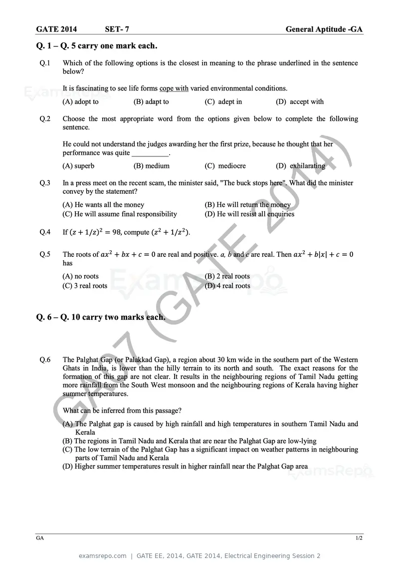
Text of page 6
GATE 2014             SET- 7                                                              General Aptitude -GA

Q. 1 – Q. 5 carry one mark each.
Q.1    Which of the following options is the closest in meaning to the phrase underlined in the sentence
       below?

       It is fascinating to see life forms cope with varied environmental conditions.
      (A) adopt to               (B) adapt to               (C) adept in              (D) accept with

Q.2    Choose the most appropriate word from the options given below to complete the following
       sentence.

       He could not understand the judges awarding her the first prize, because he thought that her
       performance was quite __________.


Q.3
      (A) superb                 (B) medium
                                                                   20
                                                            (C) mediocre


                                                                     14
                                                                                      (D) exhilarating

       In a press meet on the recent scam, the minister said, "The buck stops here". What did the minister
       convey by the statement?


Q.4
      (A) He wants all the money
      (C) He will assume final responsibility

       If (zz + 1/zz)2 = 98, compute (zz 2 + 1/zz 2 ).
                                                                        )
                                                            (B) He will return the money
                                                            (D) He will resist all enquiries


Q.5

                                       AT
       The roots of aaxx 2 + bbbb + cc = 0 are real and positive. a, b and c are real. Then aaxx 2 + bb|xx| + cc = 0
       has
      (A) no roots
      (C) 3 real roots
                                          E                 (B) 2 real roots
                                                            (D) 4 real roots


                          (G
Q. 6 – Q. 10 carry two marks each.


Q.6
                7
       The Palghat Gap (or Palakkad Gap), a region about 30 km wide in the southern part of the Western
       Ghats in India, is lower than the hilly terrain to its north and south. The exact reasons for the

     A0formation of this gap are not clear. It results in the neighbouring regions of Tamil Nadu getting
       more rainfall from the South West monsoon and the neighbouring regions of Kerala having higher
       summer temperatures.

       What can be inferred from this passage?

G     (A) The Palghat gap is caused by high rainfall and high temperatures in southern Tamil Nadu and
          Kerala
      (B) The regions in Tamil Nadu and Kerala that are near the Palghat Gap are low-lying
      (C) The low terrain of the Palghat Gap has a significant impact on weather patterns in neighbouring
          parts of Tamil Nadu and Kerala
      (D) Higher summer temperatures result in higher rainfall near the Palghat Gap area


GA                                                                                                                     1/2
Text of page 7
GATE 2014             SET- 7                                                          General Aptitude -GA
Q.7    Geneticists say that they are very close to confirming the genetic roots of psychiatric illnesses such
       as depression and schizophrenia, and consequently, that doctors will be able to eradicate these
       diseases through early identification and gene therapy.

       On which of the following assumptions does the statement above rely?
       (A) Strategies are now available for eliminating psychiatric illnesses
       (B) Certain psychiatric illnesses have a genetic basis
       (C) All human diseases can be traced back to genes and how they are expressed
       (D) In the future, genetics will become the only relevant field for identifying psychiatric illnesses

Q.8    Round-trip tickets to a tourist destination are eligible for a discount of 10% on the total fare. In
       addition, groups of 4 or more get a discount of 5% on the total fare. If the one way single person
       fare is Rs 100, a group of 5 tourists purchasing round-trip tickets will be charged Rs _________.

Q.9
                                                               20
       In a survey, 300 respondents were asked whether they own a vehicle or not. If yes, they were


                                                                 14
       further asked to mention whether they own a car or scooter or both. Their responses are tabulated
       below. What percent of respondents do not own a scooter?


                                    Own vehicle
                                                        Car
                                                        Scooter
                                                        Both
                                                                    )
                                                                    Men
                                                                     40
                                                                     30
                                                                     60
                                                                             Women
                                                                               34
                                                                               20
                                                                               46


                                      AT
                                     Do not own vehicle               20         50

Q.10

                                         E
       When a point inside of a tetrahedron (a solid with four triangular surfaces) is connected by straight
       lines to its corners, how many (new) internal planes are created with these lines? _____________


                         (G   END OF THE QUESTION PAPER


               7
     A0
G

GA                                                                                                             2/2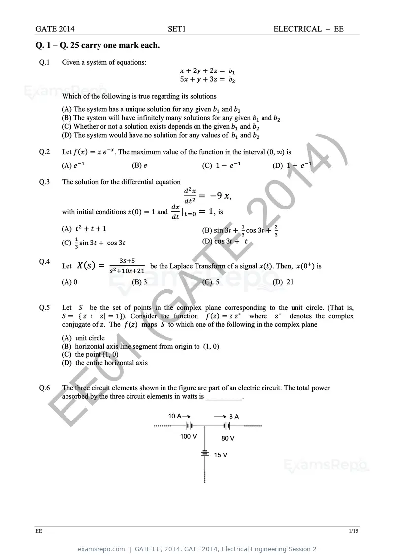
Text of page 8
GATE 2014                                          SET1                                   ELECTRICAL – EE

Q. 1 – Q. 25 carry one mark each.
 Q.1   Given a system of equations:
                                                          2     2
                                                      5         3

       Which of the following is true regarding its solutions
       (A) The system has a unique solution for any given and
       (B) The system will have infinitely many solutions for any given             and
       (C) Whether or not a solution exists depends on the given and
       (D) The system would have no solution for any values of      and

 Q.2   Let                   . The maximum value of the function in the interval (0, ∞) is


 Q.3
       (A)                         (B)

       The solution for the differential equation
                                                              (C) 1
                                                                                  14 )    (D) 1


                                                                    9 ,
       with initial conditions

       (A)             1
                                    0      1 and      |        1, is 20
                                                              (B) sin 3         cos 3
       (C)     sin 3       cos 3                              (D) cos 3

 Q.4
       Let
                                                          E
                                           be the Laplace Transform of a signal           . Then,   0   is


 Q.5
       (A) 0


       Let
                                   (B) 3 AT                   (C) 5                       (D) 21


                be the set of points in the complex plane corresponding to the unit circle. (That is,

                            (G
                ∶ | | 1 ). Consider the function
       conjugate of . The
       (A) unit circle
                                maps
                                                                   ∗
                                                                     where      ∗
                                                                                   denotes the complex
                                          to which one of the following in the complex plane

       (B) horizontal axis line segment from origin to (1, 0)
       (C) the point (1, 0)


 Q.6
        01
       (D) the entire horizontal axis


       The three circuit elements shown in the figure are part of an electric circuit. The total power

EE     absorbed by the three circuit elements in watts is __________.

                                                   10 A                    8A


                                                      100 V           80 V

                                                                    15 V


EE                                                                                                           1/15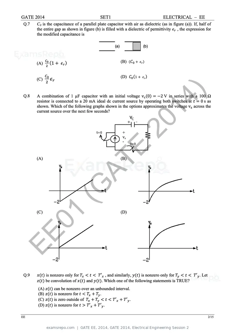
Text of page 9
GATE 2014                                    SET1                                  ELECTRICAL – EE
 Q.7   C0 is the capacitance of a parallel plate capacitor with air as dielectric (as in figure (a)). If, half of
       the entire gap as shown in figure (b) is filled with a dielectric of permittivity , the expression for
       the modified capacitance is

                                                      (a)                 (b)


       (A)      1                                           (B)   0


                                                            (D)       1
       (C)


 Q.8   A combination of 1 µF capacitor with an initial voltage v 0
                                                                                14
                                                                            2 V in series with a 100 Ω
       resistor is connected to a 20 mA ideal dc current source by operating both switches at

                                                                                   )              0 s as
       shown. Which of the following graphs shown in the options approximates the voltage v across the
       current source over the next few seconds?


                                                            +
                                                            vs
                                                            -
                                                                  20
       (A)
                                                    E       (B)

                                     AT
                        (G
        01
       (C)                                                  (D)


EE
 Q.9         is nonzero only for             ′ , and similarly,      is nonzero only for                ′ . Let
             be convolution of       and      . Which one of the following statements is TRUE?
       (A)       can be nonzero over an unbounded interval.
       (B)       is nonzero for           .
       (C)       is zero outside of               ′     ′ .
       (D)       is nonzero for     ′     ′ .

EE                                                                                                                2/15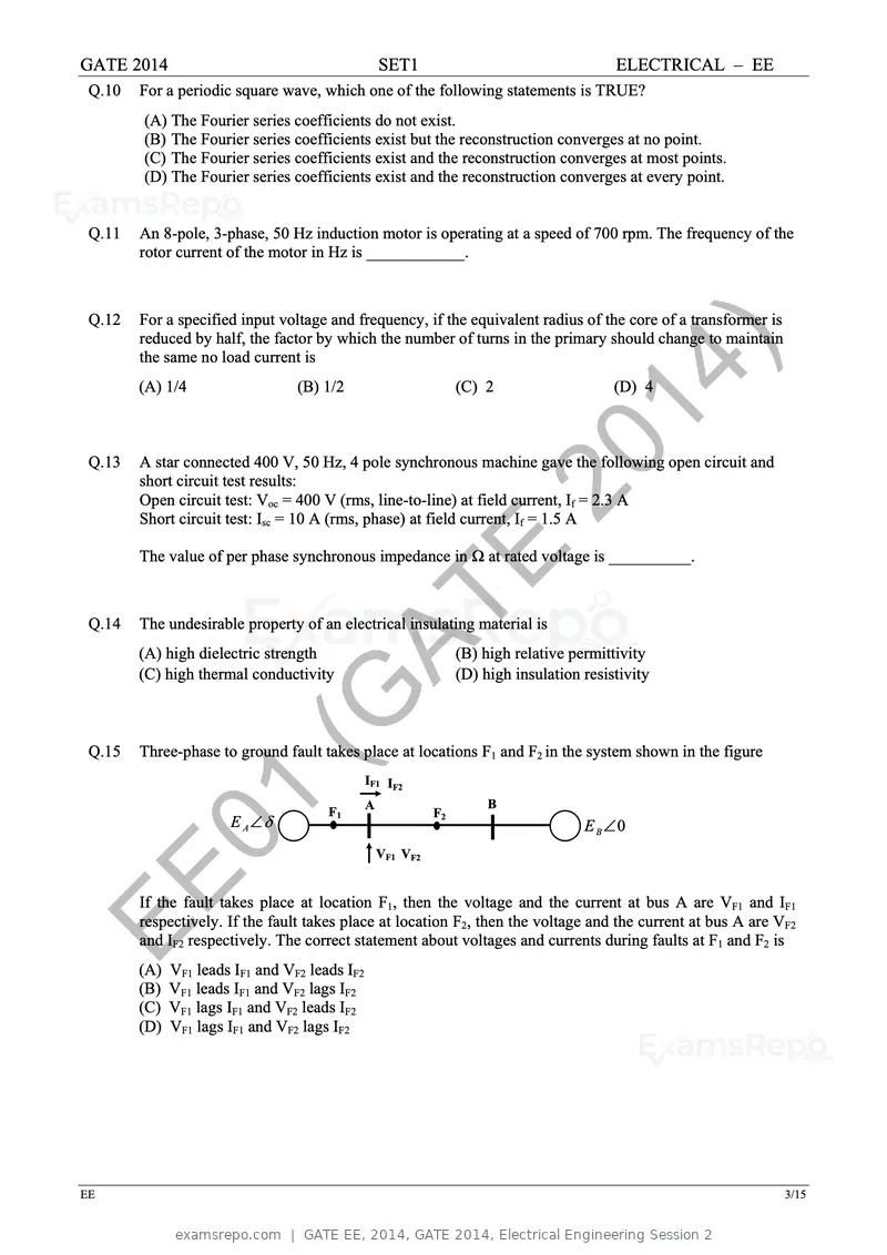
Text of page 10
GATE 2014 SET1 ELECTRICAL – EE
Q.10 For a periodic square wave, which one of the following statements is TRUE?
(A) The Fourier series coefficients do not exist.
(B) The Fourier series coefficients exist but the reconstruction converges at no point.
(C) The Fourier series coefficients exist and the reconstruction converges at most points.
(D) The Fourier series coefficients exist and the reconstruction converges at every point.
Q.11 An 8-pole, 3-phase, 50 Hz induction motor is operating at a speed of 700 rpm. The frequency of the
rotor current of the motor in Hz is ____________.
Q.12 For a specified input voltage and frequency, if the equivalent radius of the core of a transformer is
reduced by half, the factor by which the number of turns in the primary should change to maintain
the same no load current is
(A) 1/4 (B) 1/2 (C) 2 14 ) (D) 4
Q.13
20
A star connected 400 V, 50 Hz, 4 pole synchronous machine gave the following open circuit and
short circuit test results:
Open circuit test: Voc = 400 V (rms, line-to-line) at field current, If = 2.3 A
Short circuit test: Isc = 10 A (rms, phase) at field current, If = 1.5 A
E
The value of per phase synchronous impedance in Ω at rated voltage is __________.
Q.14
AT
The undesirable property of an electrical insulating material is
(A) high dielectric strength
(C) high thermal conductivity
(B) high relative permittivity
(D) high insulation resistivity
Q.15
(G
Three-phase to ground fault takes place at locations F1 and F2 in the system shown in the figure
IF1 IF2
01 E A ~
F1
A
VF1 VF2
F2
B
~ E 0B
EE If the fault takes place at location F1, then the voltage and the current at bus A are VF1 and IF1
respectively. If the fault takes place at location F2, then the voltage and the current at bus A are VF2
and IF2 respectively. The correct statement about voltages and currents during faults at F1 and F2 is
(A) VF1 leads IF1 and VF2 leads IF2
(B) VF1 leads IF1 and VF2 lags IF2
(C) VF1 lags IF1 and VF2 leads IF2
(D) VF1 lags IF1 and VF2 lags IF2
EE 3/15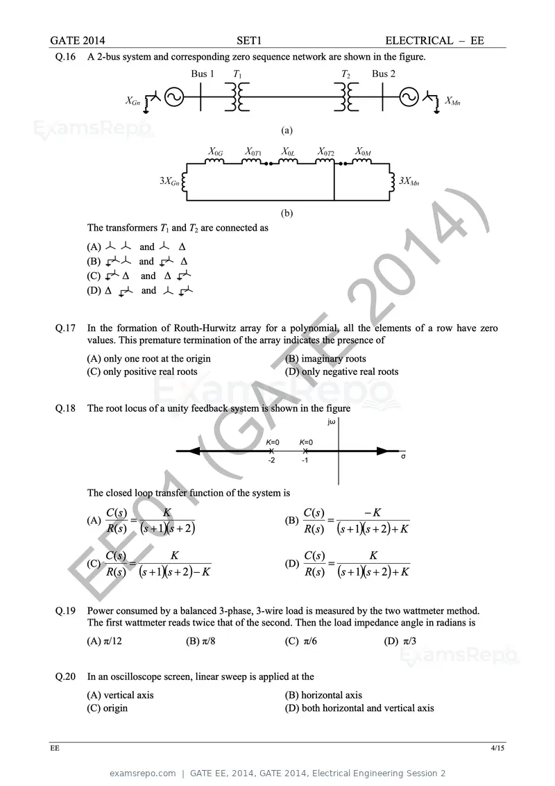
Text of page 11
GATE 2014 SET1 ELECTRICAL – EE
Q.16 A 2-bus system and corresponding zero sequence network are shown in the figure.
The transformers T1 and T2 are connected as
(A)
(B)
and
and
14 )
(C) and
Q.17
(D) and
20
In the formation of Routh-Hurwitz array for a polynomial, all the elements of a row have zero
values. This premature termination of the array indicates the presence of
(A) only one root at the origin
(C) only positive real roots
E (B) imaginary roots
(D) only negative real roots
Q.18
AT
The root locus of a unity feedback system is shown in the figure
(G
The closed loop transfer function of the system is
01
(A)
C (s)
K
R( s) s 1s 2
(B)
C (s)
K
R( s) s 1s 2 K
EE (C)
C (s)
K
R( s) s 1s 2 K
(D)
C (s)
K
R( s) s 1s 2 K
Q.19 Power consumed by a balanced 3-phase, 3-wire load is measured by the two wattmeter method.
The first wattmeter reads twice that of the second. Then the load impedance angle in radians is
(A) π/12 (B) π/8 (C) π/6 (D) π/3
Q.20 In an oscilloscope screen, linear sweep is applied at the
(A) vertical axis (B) horizontal axis
(C) origin (D) both horizontal and vertical axis
EE 4/15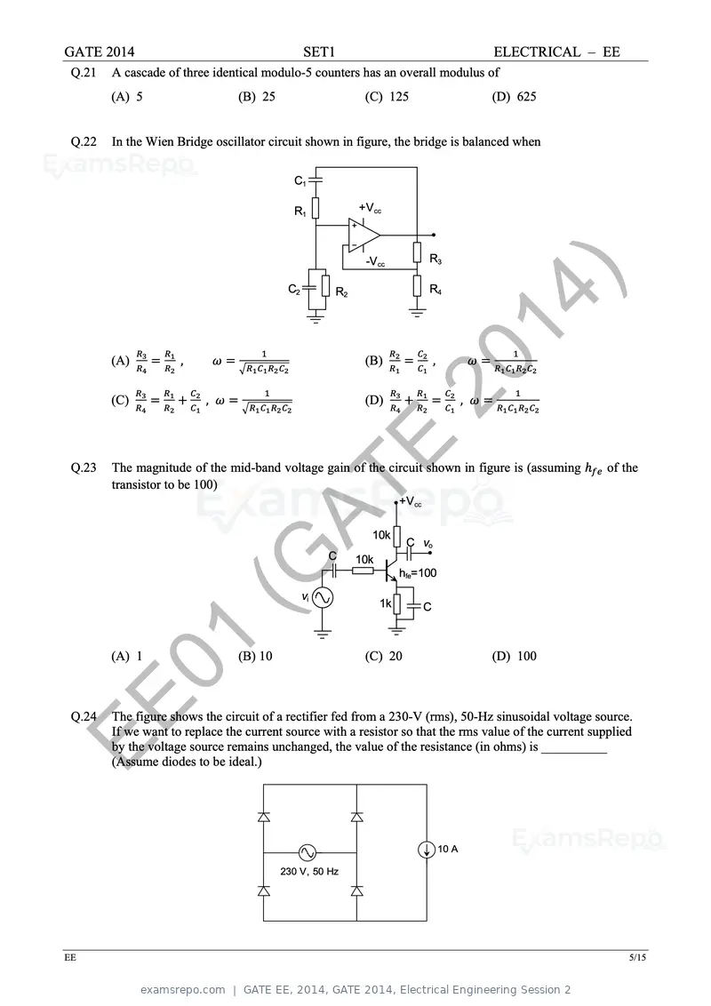
Text of page 12
GATE 2014                                      SET1                                           ELECTRICAL – EE
 Q.21   A cascade of three identical modulo-5 counters has an overall modulus of
        (A) 5                   (B) 25                    (C) 125                             (D) 625


 Q.22   In the Wien Bridge oscillator circuit shown in figure, the bridge is balanced when

                                           C1

                                           R1            +Vcc


                                                          -Vcc             R3

                                          C2        R2                     R4
                                                                                          14 )
        (A)          ,                                    (B)                  ,


        (C)               ,                               (D)
                                                                    20                    ,


 Q.23                                                   E
        The magnitude of the mid-band voltage gain of the circuit shown in figure is (assuming             of the
        transistor to be 100)

                                     AT                    10k
                                                                    +Vcc


                                                                     C vo


                         (G                    vi
                                                    C    10k


                                                               1k
                                                                    hfe=100

                                                                           C


         01
        (A) 1                   (B) 10                    (C) 20                              (D) 100


EE
 Q.24   The figure shows the circuit of a rectifier fed from a 230-V (rms), 50-Hz sinusoidal voltage source.
        If we want to replace the current source with a resistor so that the rms value of the current supplied
        by the voltage source remains unchanged, the value of the resistance (in ohms) is __________
        (Assume diodes to be ideal.)


                                                                                   10 A

                                         230 V, 50 Hz


EE                                                                                                              5/15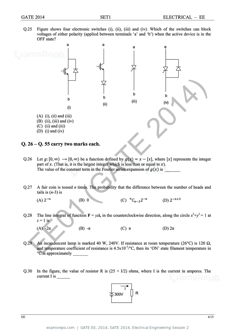
Text of page 13
GATE 2014                                     SET1                                  ELECTRICAL – EE

 Q.25   Figure shows four electronic switches (i), (ii), (iii) and (iv). Which of the switches can block
        voltages of either polarity (applied between terminals ‘a’ and ‘b’) when the active device is in the
        OFF state?
                           a                   a
                                                                   a                a


                            b

                           (i)
                                               b
                                               (ii)
                                                                   b
                                                                  (iii)        14 )
                                                                                     b
                                                                                    (iv)


        (A) (i), (ii) and (iii)
        (B) (ii), (iii) and (iv)
        (C) (ii) and (iii)
        (D) (i) and (iv)                                         20
Q. 26 – Q. 55 carry two marks each.

 Q.26   Let : 0, ∞ ⟶ 0, ∞ be a function defined by
                                                      E                        , where     represents the integer

                                       AT
        part of . (That is, it is the largest integer which is less than or equal to ).
        The value of the constant term in the Fourier series expansion of           is _______


 Q.27
                           (G
        A fair coin is tossed n times. The probability that the difference between the number of heads and
        tails is (n-3) is
        (A) 2                      (B) 0                  (C)              2       (D) 2


 Q.28
         01
        The line integral of function F = yzi, in the counterclockwise direction, along the circle x2+y2 = 1 at
        z = 1 is
        (A) -2π                    (B) -π                 (C) π                    (D) 2π


EE
 Q.29   An incandescent lamp is marked 40 W, 240V. If resistance at room temperature (26°C) is 120 Ω,
        and temperature coefficient of resistance is 4.5x10⁻³/°C, then its ‘ON’ state filament temperature in
        °C is approximately _______


 Q.30   In the figure, the value of resistor R is (25 + I/2) ohms, where I is the current in amperes. The
        current I is ______

                                                             I
                                                      300V             R


EE                                                                                                             6/15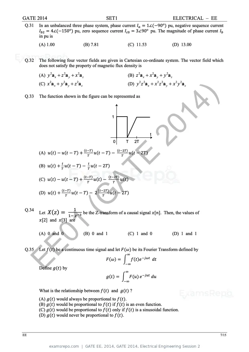
Text of page 14
GATE 2014 SET1 ELECTRICAL – EE
Q.31 In an unbalanced three phase system, phase current 1∠ 90o pu, negative sequence current
o o
4∠ 150 pu, zero sequence current 3∠90 pu. The magnitude of phase current
in pu is
(A) 1.00 (B) 7.81 (C) 11.53 (D) 13.00
Q.32 The following four vector fields are given in Cartesian co-ordinate system. The vector field which
does not satisfy the property of magnetic flux density is
(A) y a x z a y x a z (B) z a x x a y y a z
2 2 2 2 2 2
(C) x a x y a y z a z (D) y z a x x z a y x y a z
2 2 2 2 2 2 2 2 2
Q.33 The function shown in the figure can be represented as
1
14 )
0 T 2T
20 t
(A) 2
(B) 2
E
(C)
(D)
AT
2 2
Q.34
Let
2 and 3 are
(G be the Z-transform of a causal signal . Then, the values of
01
(A) 0 and 0 (B) 0 and 1 (C) 1 and 0 (D) 1 and 1
EE
Q.35 Let
Define
be a continuous time signal and let
by
be its Fourier Transform defined by
What is the relationship between and ?
(A) would always be proportional to .
(B) would be proportional to if is an even function.
(C) would be proportional to only if is a sinusoidal function.
(D) would never be proportional to .
EE 7/15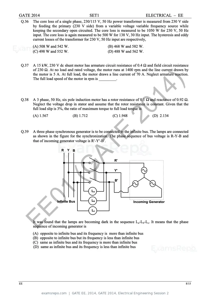
Text of page 15
GATE 2014 SET1 ELECTRICAL – EE
Q.36 The core loss of a single phase, 230/115 V, 50 Hz power transformer is measured from 230 V side
by feeding the primary (230 V side) from a variable voltage variable frequency source while
keeping the secondary open circuited. The core loss is measured to be 1050 W for 230 V, 50 Hz
input. The core loss is again measured to be 500 W for 138 V, 30 Hz input. The hysteresis and eddy
current losses of the transformer for 230 V, 50 Hz input are respectively,
(A) 508 W and 542 W. (B) 468 W and 582 W.
(C) 498 W and 552 W. (D) 488 W and 562 W.
Q.37 A 15 kW, 230 V dc shunt motor has armature circuit resistance of 0.4 Ω and field circuit resistance
of 230 Ω. At no load and rated voltage, the motor runs at 1400 rpm and the line current drawn by
the motor is 5 A. At full load, the motor draws a line current of 70 A. Neglect armature reaction.
The full load speed of the motor in rpm is _________.
Q.38
14 )
A 3 phase, 50 Hz, six pole induction motor has a rotor resistance of 0.1 Ω and reactance of 0.92 Ω.
Neglect the voltage drop in stator and assume that the rotor resistance is constant. Given that the
20
full load slip is 3%, the ratio of maximum torque to full load torque is
(A) 1.567 (B) 1.712 (C) 1.948 (D) 2.134
Q.39 A three phase synchronous generator is to be connected to the infinite bus. The lamps are connected
E
as shown in the figure for the synchronization. The phase sequence of bus voltage is R-Y-B and
that of incoming generator voltage is R-Y-B.
R Y B
AT R'
(G Y'
B'
01 Infinite Bus
La
Lb Incoming Generator
EE Lc
It was found that the lamps are becoming dark in the sequence La-Lb-Lc. It means that the phase
sequence of incoming generator is
(A) opposite to infinite bus and its frequency is more than infinite bus
(B) opposite to infinite bus but its frequency is less than infinite bus
(C) same as infinite bus and its frequency is more than infinite bus
(D) same as infinite bus and its frequency is less than infinite bus
EE 8/15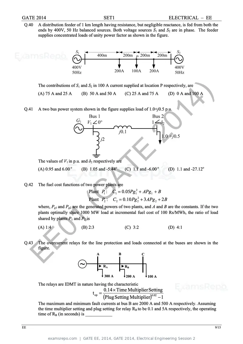
Text of page 16
GATE 2014 SET1 ELECTRICAL – EE
Q.40 A distribution feeder of 1 km length having resistance, but negligible reactance, is fed from both the
ends by 400V, 50 Hz balanced sources. Both voltage sources S1 and S2 are in phase. The feeder
supplies concentrated loads of unity power factor as shown in the figure.
The contributions of S1 and S2 in 100 A current supplied at location P respectively, are
(A) 75 A and 25 A (B) 50 A and 50 A (C) 25 A and 75 A (D) 0 A and 100 A
Q.41 A two bus power system shown in the figure supplies load of 1.0+j0.5 p.u.
14 )
20
The values of V1 in p.u. and δ2 respectively are
E
Q.42
(A) 0.95 and 6.00 o
AT
(B) 1.05 and -5.44o
The fuel cost functions of two power plants are
(C) 1.1 and -6.00 o (D) 1.1 and -27.12o
C1 0.05Pg12 APg1 B
(G Plant P1 :
Plant P2 : C2 0.10 Pg 22 3 APg 2 2 B
where, Pg1 and Pg2 are the generated powers of two plants, and A and B are the constants. If the two
plants optimally share 1000 MW load at incremental fuel cost of 100 Rs/MWh, the ratio of load
shared by plants P1 and P2 is
01
(A) 1:4 (B) 2:3 (C) 3:2 (D) 4:1
EE
Q.43 The overcurrent relays for the line protection and loads connected at the buses are shown in the
figure.
~
A B C
RA RB
300 A 200 A 100 A
The relays are IDMT in nature having the characteristic
0.14 Time Multiplier Setting
t op
Plug Setting Multiplier0.02 1
The maximum and minimum fault currents at bus B are 2000 A and 500 A respectively. Assuming
the time multiplier setting and plug setting for relay RB to be 0.1 and 5A respectively, the operating
time of RB (in seconds) is ____________
EE 9/15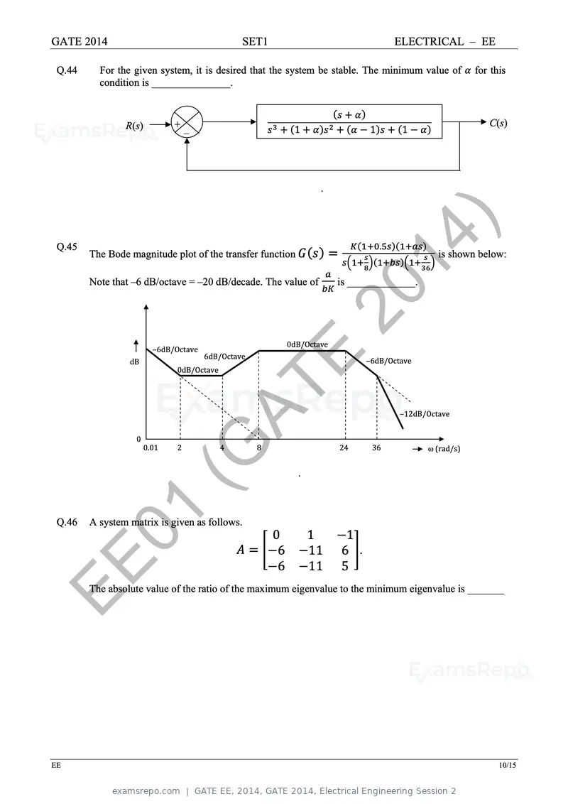
Text of page 17
GATE 2014 SET1 ELECTRICAL – EE
Q.44 For the given system, it is desired that the system be stable. The minimum value of for this
condition is _______________.
R(s) + C(s)
‒ 1 1 1
.
Q.45
The Bode magnitude plot of the transfer function
14 ).
is shown below:
Note that ‒6 dB/octave = ‒20 dB/decade. The value of is _____________.
20
0dB/Octave
‒6dB/Octave
dB
6dB/Octave
0dB/Octave E ‒6dB/Octave
0
AT ‒12dB/Octave
0.01
(G
2 4 8
.
24 36 (rad/s)
Q.46
01
A system matrix is given as follows.
0
6
1
11
1
6 .
EE 6 11 5
The absolute value of the ratio of the maximum eigenvalue to the minimum eigenvalue is _______
EE 10/15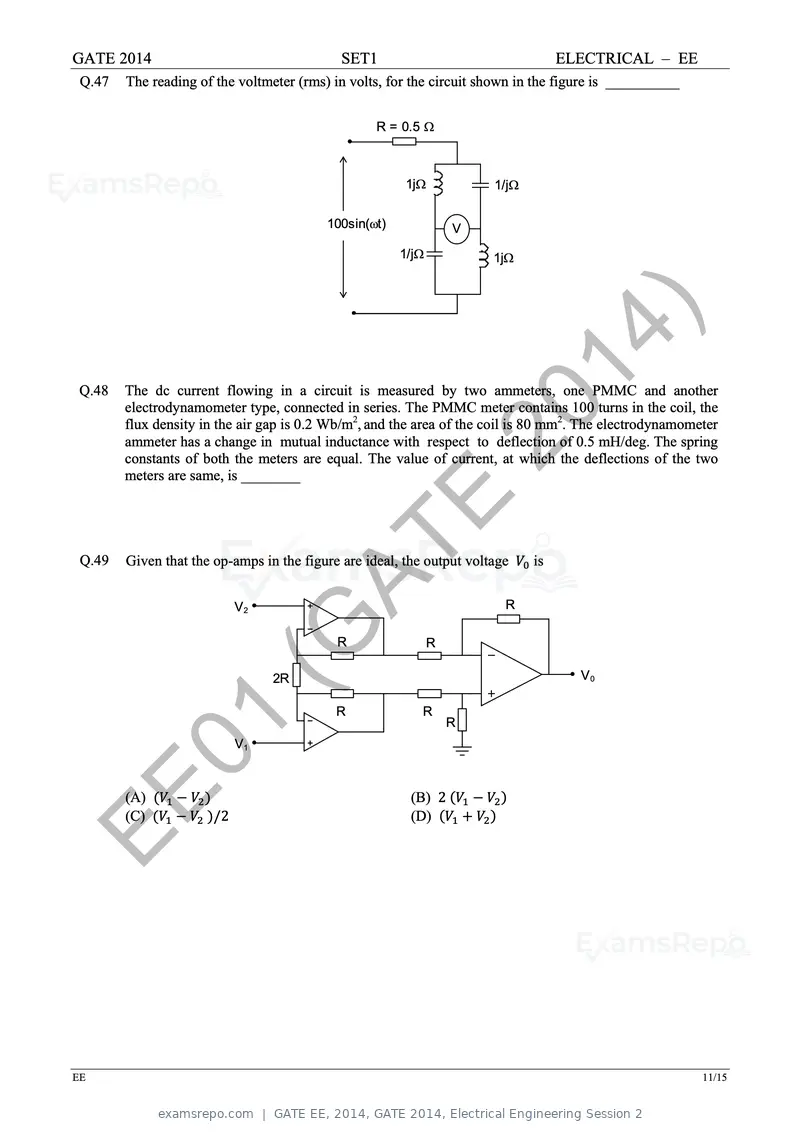
Text of page 18
GATE 2014 SET1 ELECTRICAL – EE
Q.47 The reading of the voltmeter (rms) in volts, for the circuit shown in the figure is __________
R = 0.5
1j 1/j
100sin(t) V
1/j 1j
Q.48
14 )
The dc current flowing in a circuit is measured by two ammeters, one PMMC and another
electrodynamometer type, connected in series. The PMMC meter contains 100 turns in the coil, the
20
flux density in the air gap is 0.2 Wb/m2, and the area of the coil is 80 mm2. The electrodynamometer
ammeter has a change in mutual inductance with respect to deflection of 0.5 mH/deg. The spring
constants of both the meters are equal. The value of current, at which the deflections of the two
meters are same, is ________
E
Q.49
AT
Given that the op-amps in the figure are ideal, the output voltage
V2 R
is
(G 2R
R R
V0
R R
01 V1
R
EE (A)
(C) /2
(B) 2
(D)
EE 11/15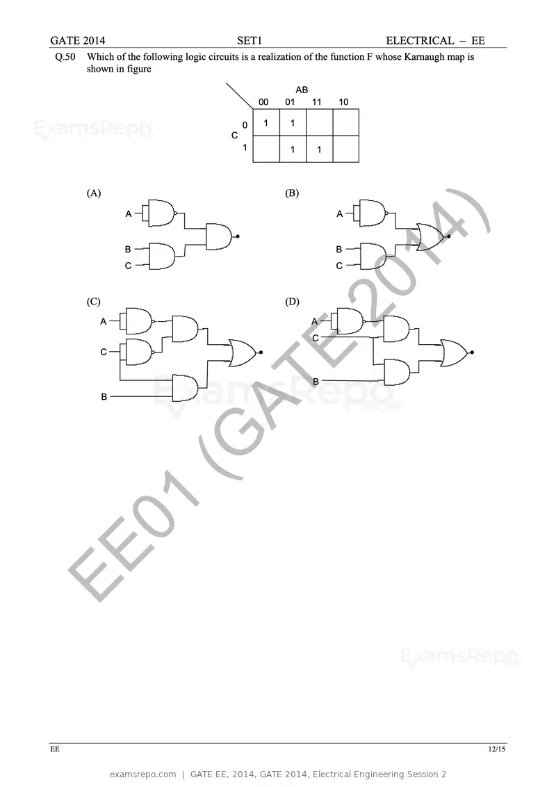
Text of page 19
GATE 2014                                   SET1                                ELECTRICAL – EE
 Q.50   Which of the following logic circuits is a realization of the function F whose Karnaugh map is
        shown in figure

                                                             AB
                                                   00   01        11   10

                                               0   1     1
                                           C
                                               1         1        1


        (A)                                             (B)

                  A                                                    A


                  B
                  C
                                                                       B
                                                                       C
                                                                            14 )
        (C)
           A
                                                        (D)       20
                                                                  A
                                                                  C
           C
                                                    E
              B
                                     AT                           B


                        (G
         01
EE

EE                                                                                                       12/15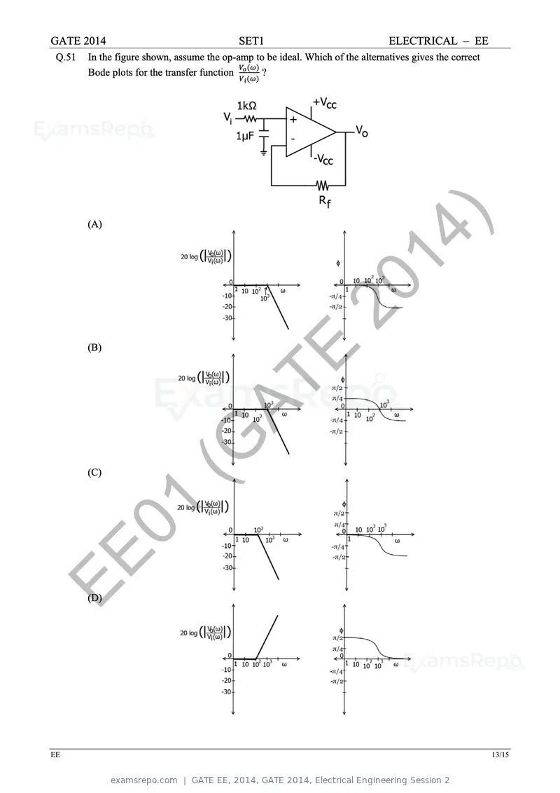
Text of page 20
GATE 2014                                   SET1                                ELECTRICAL – EE
 Q.51   In the figure shown, assume the op-amp to be ideal. Which of the alternatives gives the correct
        Bode plots for the transfer function     ?


        (A)
                                                                          14 )
                                                             20
        (B)
                                                   E
                                     AT
        (C)
                        (G
         01
EE      (D)


EE                                                                                                        13/15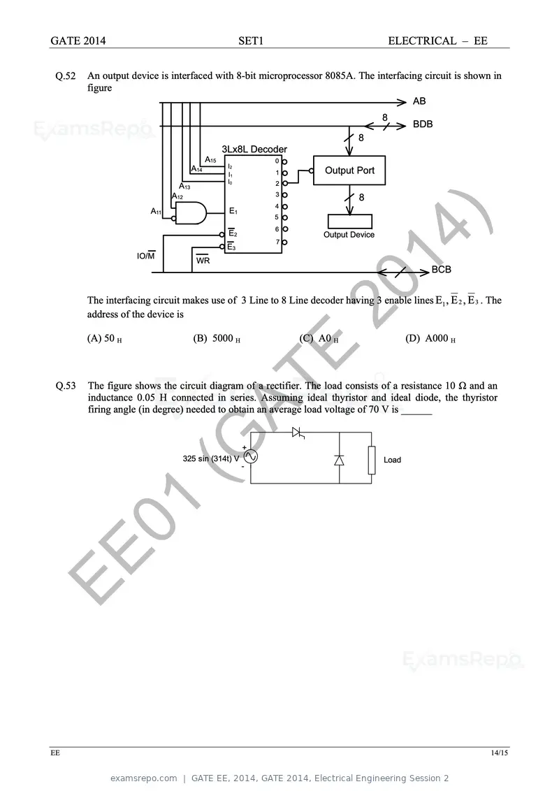
Text of page 21
GATE 2014                                              SET1                               ELECTRICAL – EE


 Q.52   An output device is interfaced with 8-bit microprocessor 8085A. The interfacing circuit is shown in
        figure
                                                                                              AB
                                                                                      8
                                                                                              BDB
                                                                              8
                                                 3Lx8L Decoder
                                           A15                0
                                     A14          I2
                                                  I1          1        Output Port
                                                  I0          2
                               A13
                             A12                              3
                                                                              8
                                                              4
                       A11                        E1


                    IO/M
                                      WR
                                                  E2
                                                  E3
                                                              5
                                                              6

                                                              7                14
                                                                      Output Device


                                                                                  )                BCB


                                                                    20
        The interfacing circuit makes use of 3 Line to 8 Line decoder having 3 enable lines E1 , E 2 , E 3 . The
        address of the device is

        (A) 50 H                     (B) 5000 H                   (C) A0 H                   (D) A000 H

                                                              E
 Q.53
                                           AT
        The figure shows the circuit diagram of a rectifier. The load consists of a resistance 10 Ω and an
        inductance 0.05 H connected in series. Assuming ideal thyristor and ideal diode, the thyristor
        firing angle (in degree) needed to obtain an average load voltage of 70 V is ______


                           (G   325 sin (314t) V
                                                       +

                                                       -
                                                                                      Load


         01
EE

EE                                                                                                           14/15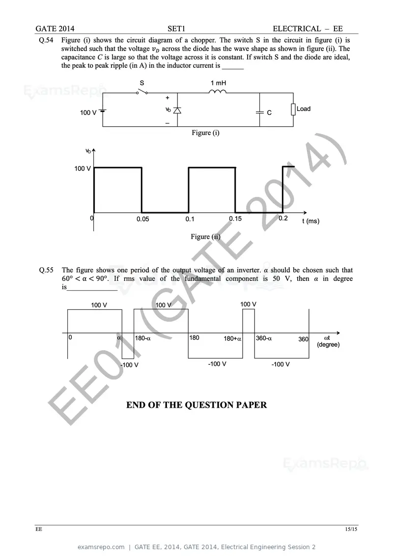
Text of page 22
GATE 2014 SET1 ELECTRICAL – EE
Q.54 Figure (i) shows the circuit diagram of a chopper. The switch S in the circuit in figure (i) is
switched such that the voltage across the diode has the wave shape as shown in figure (ii). The
capacitance C is large so that the voltage across it is constant. If switch S and the diode are ideal,
the peak to peak ripple (in A) in the inductor current is ______
S 1 mH
+
vD Load
100 V C
_
Figure (i)
vD
100 V 14 )
0 0.05 0.1
20
Figure (ii)
0.15 0.2 t (ms)
E
Q.55
AT
The figure shows one period of the output voltage of an inverter. α should be chosen such that
60o α 90o . If rms value of the fundamental component is 50 V, then α in degree
is______________
100 V 100 V 100 V
0
(G
180- 180 180+ 360- 360 t
(degree)
01 -100 V -100 V -100 V
EE END OF THE QUESTION PAPER
EE 15/15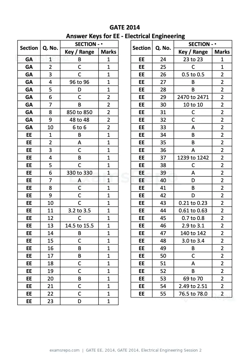
Text of page 23
GATE 2014
                 Answer Keys for EE ‐ Electrical Engineering
                      SECTION ‐ ϭ                              SECTION ‐ ϭ
Section Q. No.                           Section Q. No.
                 Key / Range Marks                        Key / Range Marks
 GA        1           B          1        EE      24        23 to 23      1
 GA        2           C          1        EE      25           C          1
 GA        3           C          1        EE      26       0.5 to 0.5     2
 GA        4       96 to 96       1        EE      27           B          2
 GA        5           D          1        EE      28           B          2
 GA        6           C          2        EE      29     2470 to 2471     2
 GA        7           B          2        EE      30        10 to 10      2
 GA       8       850 to 850      2        EE      31           C          2
 GA       9        48 to 48       2        EE      32           C          2
 GA       10         6 to 6       2        EE      33           A          2
 EE        1           B          1        EE      34           B          2
 EE        2           A          1        EE      35           B          2
 EE        3           C          1        EE      36           A          2
 EE        4           B          1        EE      37     1239 to 1242     2
 EE        5           C          1        EE      38           C          2
 EE        6      330 to 330      1        EE      39           A          2
 EE        7           A          1        EE      40           D          2
 EE        8           C          1        EE      41           B          2
 EE        9           C          1        EE      42           D          2
 EE       10           C          1        EE      43     0.21 to 0.23     2
 EE       11       3.2 to 3.5     1        EE      44     0.61 to 0.63     2
 EE       12           C          1        EE      45       0.7 to 0.8     2
 EE       13     14.5 to 15.5     1        EE      46       2.9 to 3.1     2
 EE       14           B          1        EE      47      140 to 142      2
 EE       15           C          1        EE      48       3.0 to 3.4     2
 EE       16           B          1        EE      49           B          2
 EE       17           B          1        EE      50           C          2
 EE       18           C          1        EE      51           A          2
 EE       19           C          1        EE      52           B          2
 EE       20           B          1        EE      53        69 to 70      2
 EE       21           C          1        EE      54      2.49 to 2.51    2
 EE       22           C          1        EE      55      76.5 to 78.0    2
 EE       23           D          1
Text of page 24
SESSION - 2

Text of page 25
GATE 2014: General Instructions during Examination

   1. Total duration of the GATE examination is 180 minutes.
   2. The clock will be set at the server. The countdown timer at the top right corner of
      screen will display the remaining time available for you to complete the examination.
      When the timer reaches zero, the examination will end by itself. You need not
      terminate the examination or submit your paper.
   3. Any useful data required for your paper can be viewed by clicking on the Useful
      Common Data button that appears on the screen.
   4. Use the scribble pad provided to you for any rough work. Submit the scribble pad at
      the end of the examination.
   5. You are allowed to use a non-programmable type calculator, however, sharing of
      calculators is not allowed.
   6. The Question Palette displayed on the right side of screen will show the status of
      each question using one of the following symbols:


The Marked for Review status for a question simply indicates that you would like to look at
that question again. If a question is answered, but marked for review, then the answer will
be considered for evaluation unless the status is modified by the candidate.

Navigating to a Question :

   7. To answer a question, do the following:
         a. Click on the question number in the Question Palette to go to that question
            directly.
         b. Select an answer for a multiple choice type question by clicking on the bubble
            placed before the 4 choices, namely A, B, C and D. Use the virtual numeric
            keypad to enter a number as answer for a numerical type question.
         c. Click on Save & Next to save your answer for the current question and then go
            to the next question.
         d. Click on Mark for Review & Next to save your answer for the current question
            and also mark it for review, and then go to the next question.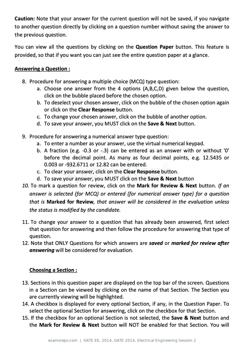
Text of page 26
Caution: Note that your answer for the current question will not be saved, if you navigate
to another question directly by clicking on a question number without saving the answer to
the previous question.

You can view all the questions by clicking on the Question Paper button. This feature is
provided, so that if you want you can just see the entire question paper at a glance.

Answering a Question :

   8. Procedure for answering a multiple choice (MCQ) type question:
         a. Choose one answer from the 4 options (A,B,C,D) given below the question,
            click on the bubble placed before the chosen option.
         b. To deselect your chosen answer, click on the bubble of the chosen option again
            or click on the Clear Response button.
         c. To change your chosen answer, click on the bubble of another option.
         d. To save your answer, you MUST click on the Save & Next button.

   9. Procedure for answering a numerical answer type question:
         a. To enter a number as your answer, use the virtual numerical keypad.
         b. A fraction (e.g. -0.3 or -.3) can be entered as an answer with or without '0'
             before the decimal point. As many as four decimal points, e.g. 12.5435 or
             0.003 or -932.6711 or 12.82 can be entered.
         c. To clear your answer, click on the Clear Response button.
         d. To save your answer, you MUST click on the Save & Next button
   10. To mark a question for review, click on the Mark for Review & Next button. If an
      answer is selected (for MCQ) or entered (for numerical answer type) for a question
      that is Marked for Review, that answer will be considered in the evaluation unless
      the status is modified by the candidate.

   11. To change your answer to a question that has already been answered, first select
      that question for answering and then follow the procedure for answering that type of
      question.
   12. Note that ONLY Questions for which answers are saved or marked for review after
      answering will be considered for evaluation.


      Choosing a Section :

   13. Sections in this question paper are displayed on the top bar of the screen. Questions
      in a Section can be viewed by clicking on the name of that Section. The Section you
      are currently viewing will be highlighted.
   14. A checkbox is displayed for every optional Section, if any, in the Question Paper. To
      select the optional Section for answering, click on the checkbox for that Section.
   15. If the checkbox for an optional Section is not selected, the Save & Next button and
      the Mark for Review & Next button will NOT be enabled for that Section. You will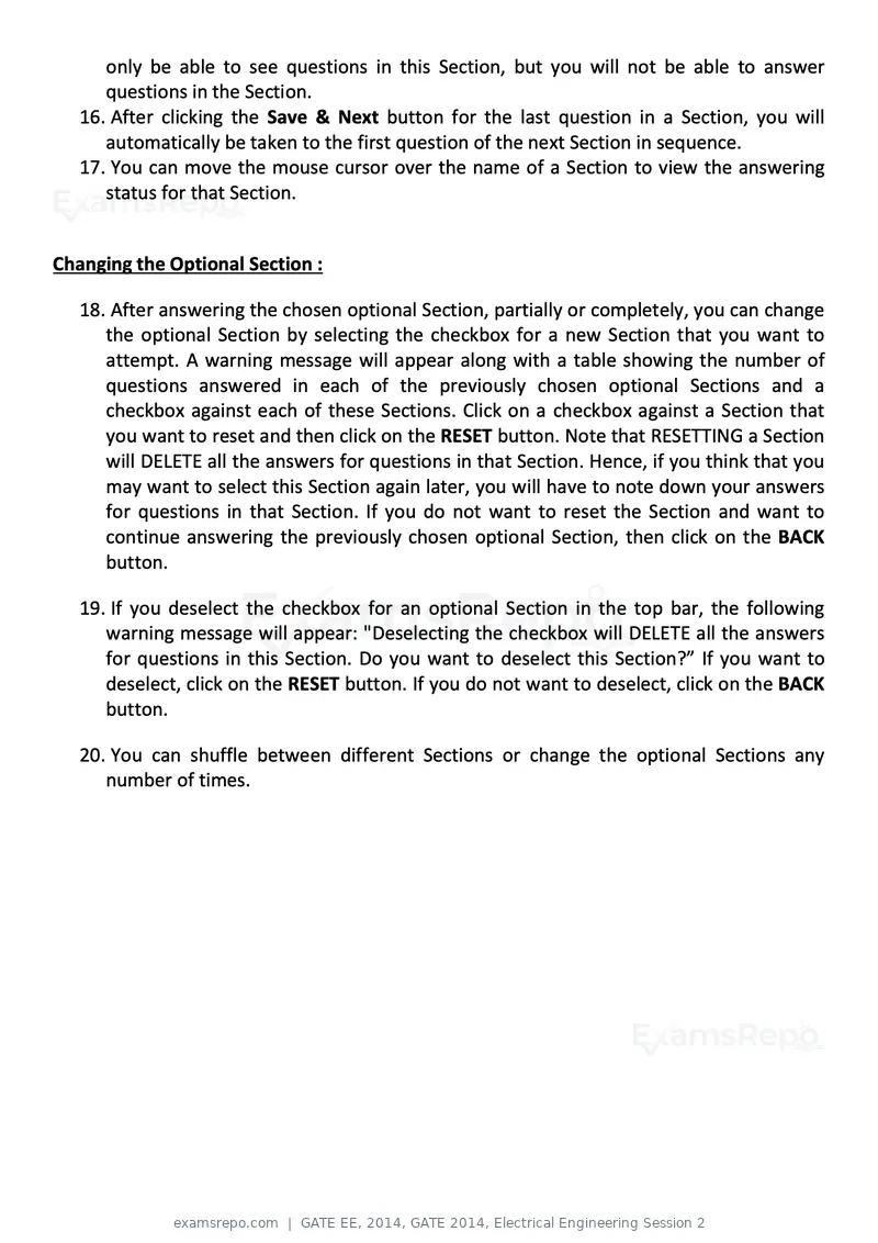
Text of page 27
only be able to see questions in this Section, but you will not be able to answer
      questions in the Section.
   16. After clicking the Save & Next button for the last question in a Section, you will
      automatically be taken to the first question of the next Section in sequence.
   17. You can move the mouse cursor over the name of a Section to view the answering
      status for that Section.


Changing the Optional Section :

   18. After answering the chosen optional Section, partially or completely, you can change
      the optional Section by selecting the checkbox for a new Section that you want to
      attempt. A warning message will appear along with a table showing the number of
      questions answered in each of the previously chosen optional Sections and a
      checkbox against each of these Sections. Click on a checkbox against a Section that
      you want to reset and then click on the RESET button. Note that RESETTING a Section
      will DELETE all the answers for questions in that Section. Hence, if you think that you
      may want to select this Section again later, you will have to note down your answers
      for questions in that Section. If you do not want to reset the Section and want to
      continue answering the previously chosen optional Section, then click on the BACK
      button.

   19. If you deselect the checkbox for an optional Section in the top bar, the following
      warning message will appear: "Deselecting the checkbox will DELETE all the answers
      for questions in this Section. Do you want to deselect this Section?” If you want to
      deselect, click on the RESET button. If you do not want to deselect, click on the BACK
      button.

   20. You can shuffle between different Sections or change the optional Sections any
      number of times.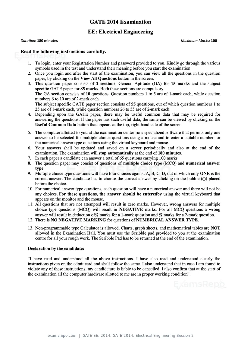
Text of page 28
GATE 2014 Examination
                                      EE: Electrical Engineering
Duration: 180 minutes                                                                        Maximum Marks: 100

Read the following instructions carefully.

    1. To login, enter your Registration Number and password provided to you. Kindly go through the various
       symbols used in the test and understand their meaning before you start the examination.
    2. Once you login and after the start of the examination, you can view all the questions in the question
       paper, by clicking on the View All Questions button in the screen.
    3. This question paper consists of 2 sections, General Aptitude (GA) for 15 marks and the subject
       specific GATE paper for 85 marks. Both these sections are compulsory.
       The GA section consists of 10 questions. Question numbers 1 to 5 are of 1-mark each, while question
       numbers 6 to 10 are of 2-mark each.
       The subject specific GATE paper section consists of 55 questions, out of which question numbers 1 to
       25 are of 1-mark each, while question numbers 26 to 55 are of 2-mark each.
    4. Depending upon the GATE paper, there may be useful common data that may be required for
       answering the questions. If the paper has such useful data, the same can be viewed by clicking on the
       Useful Common Data button that appears at the top, right hand side of the screen.
    5. The computer allotted to you at the examination center runs specialized software that permits only one
        answer to be selected for multiple-choice questions using a mouse and to enter a suitable number for
        the numerical answer type questions using the virtual keyboard and mouse.
    6. Your answers shall be updated and saved on a server periodically and also at the end of the
        examination. The examination will stop automatically at the end of 180 minutes.
    7. In each paper a candidate can answer a total of 65 questions carrying 100 marks.
    8. The question paper may consist of questions of multiple choice type (MCQ) and numerical answer
        type.
    9. Multiple choice type questions will have four choices against A, B, C, D, out of which only ONE is the
        correct answer. The candidate has to choose the correct answer by clicking on the bubble (⃝) placed
        before the choice.
    10. For numerical answer type questions, each question will have a numerical answer and there will not be
        any choices. For these questions, the answer should be enteredby using the virtual keyboard that
        appears on the monitor and the mouse.
    11. All questions that are not attempted will result in zero marks. However, wrong answers for multiple
        choice type questions (MCQ) will result in NEGATIVE marks. For all MCQ questions a wrong
        answer will result in deduction of⅓ marks for a 1-mark question and ⅔ marks for a 2-mark question.
    12. There is NO NEGATIVE MARKING for questions of NUMERICAL ANSWER TYPE.
    13. Non-programmable type Calculator is allowed. Charts, graph sheets, and mathematical tables are NOT
        allowed in the Examination Hall. You must use the Scribble pad provided to you at the examination
        centre for all your rough work. The Scribble Pad has to be returned at the end of the examination.

    Declaration by the candidate:

    “I have read and understood all the above instructions. I have also read and understood clearly the
    instructions given on the admit card and shall follow the same. I also understand that in case I am found to
    violate any of these instructions, my candidature is liable to be cancelled. I also confirm that at the start of
    the examination all the computer hardware allotted to me are in proper working condition”.
Text of page 29
GATE 2014            SET- 8                                                        General Aptitude -GA

Q. 1 – Q. 5 carry one mark each.
Q.1    Choose the most appropriate phrase from the options given below to complete the following
       sentence.

       India is a post-colonial country because
      (A) it was a former British colony
      (B) Indian Information Technology professionals have colonized the world
      (C) India does not follow any colonial practices
      (D) India has helped other countries gain freedom

Q.2    Who ___________ was coming to see us this evening?


Q.3
       (A) you said
       (C) did you say that

       Match the columns.
       Column 1
                                                              20
                                                        (B) did you say
                                                        (D) had you said


                                                  Column 2
                                                                14
       1) eradicate
       2) distort
       3) saturate
       4) utilize
                                                  P) misrepresent

                                                                   )
                                                  Q) soak completely
                                                  R) use
                                                  S) destroy utterly

      (A) 1:S, 2:P, 3:Q, 4:R
      (C) 1:Q, 2:R, 3:S, 4:P
                                     AT                 (B) 1:P, 2:Q, 3:R, 4:S
                                                        (D) 1:S, 2:P, 3:R, 4:Q

Q.4


Q.5
                                        E
       What is the average of all multiples of 10 from 2 to 198?
      (A) 90                   (B) 100                  (C) 110                  (D) 120


                        (G
       The value of �12 + �12 + √12 + ⋯ is

      (A) 3.464                (B) 3.932                (C) 4.000                (D) 4.444


               8
Q. 6 – Q. 10 carry two marks each.

Q.6
     A0The old city of Koenigsberg, which had a German majority population before World War 2, is now
       called Kaliningrad. After the events of the war, Kaliningrad is now a Russian territory and has a
       predominantly Russian population. It is bordered by the Baltic Sea on the north and the countries of
       Poland to the south and west and Lithuania to the east respectively. Which of the statements below

G      can be inferred from this passage?
      (A) Kaliningrad was historically Russian in its ethnic make up
      (B) Kaliningrad is a part of Russia despite it not being contiguous with the rest of Russia
      (C) Koenigsberg was renamed Kaliningrad, as that was its original Russian name
      (D) Poland and Lithuania are on the route from Kaliningrad to the rest of Russia


GA                                                                                                        1/2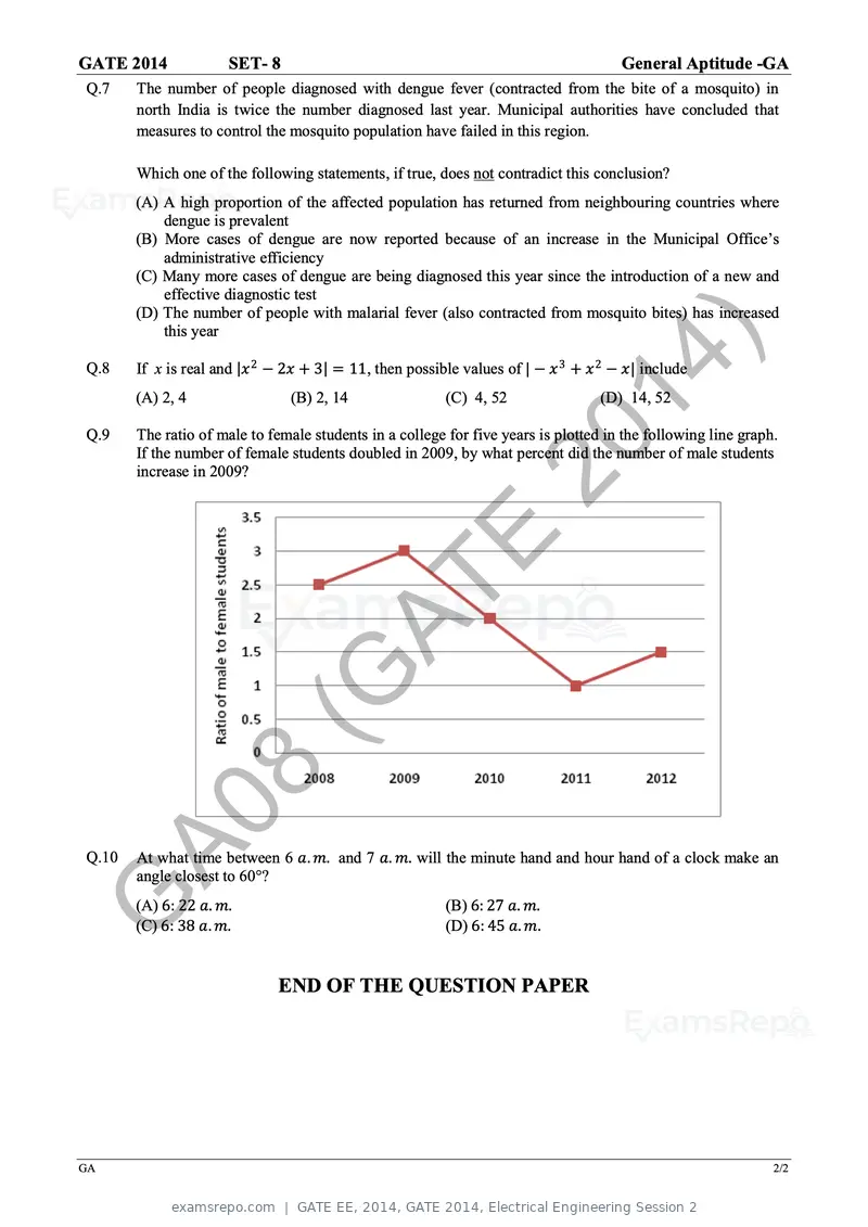
Text of page 30
GATE 2014              SET- 8                                                            General Aptitude -GA
Q.7    The number of people diagnosed with dengue fever (contracted from the bite of a mosquito) in
       north India is twice the number diagnosed last year. Municipal authorities have concluded that
       measures to control the mosquito population have failed in this region.

       Which one of the following statements, if true, does not contradict this conclusion?
       (A) A high proportion of the affected population has returned from neighbouring countries where
           dengue is prevalent
       (B) More cases of dengue are now reported because of an increase in the Municipal Office’s
           administrative efficiency
       (C) Many more cases of dengue are being diagnosed this year since the introduction of a new and
           effective diagnostic test
       (D) The number of people with malarial fever (also contracted from mosquito bites) has increased
           this year

Q.8
                                                                 20
       If x is real and |xx 2 − 2xx + 3| = 11, then possible values of | − xx 3 + xx 2 − xx| include
       (A) 2, 4                  (B) 2, 14

                                                                   14
                                                           (C) 4, 52                 (D) 14, 52


                                                                      )
Q.9    The ratio of male to female students in a college for five years is plotted in the following line graph.
       If the number of female students doubled in 2009, by what percent did the number of male students
       increase in 2009?


                                       AT
                                          E
                           (G
                  8
Q.10
     A0At what time between 6 aa. mm. and 7 aa. mm. will the minute hand and hour hand of a clock make an
       angle closest to 60°?


G      (A) 6: 22 aa. mm.
       (C) 6: 38 aa. mm.
                                                           (B) 6: 27 aa. mm.
                                                           (D) 6: 45 aa. mm.


                              END OF THE QUESTION PAPER


GA                                                                                                            2/2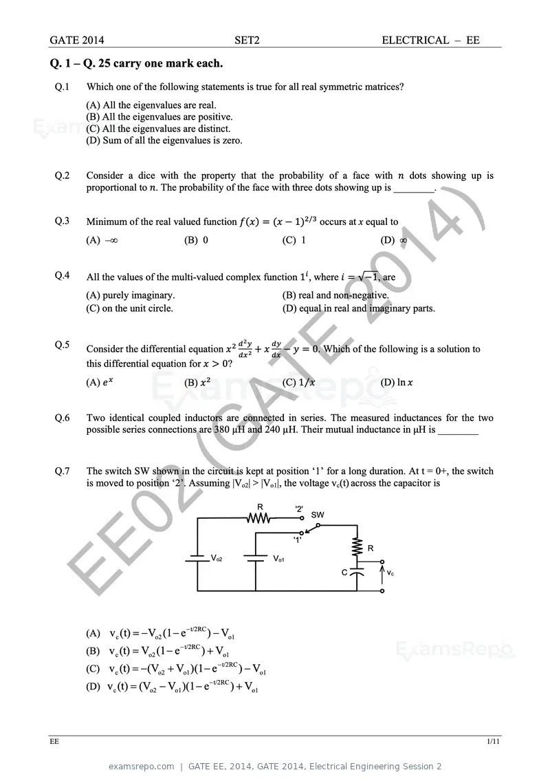
Text of page 31
GATE 2014 SET2 ELECTRICAL – EE
Q. 1 – Q. 25 carry one mark each.
Q.1 Which one of the following statements is true for all real symmetric matrices?
(A) All the eigenvalues are real.
(B) All the eigenvalues are positive.
(C) All the eigenvalues are distinct.
(D) Sum of all the eigenvalues is zero.
Q.2 Consider a dice with the property that the probability of a face with dots showing up is
proportional to . The probability of the face with three dots showing up is ________.
Q.3 Minimum of the real valued function
(A) ‒∞ (B) 0
1
(C) 1
/
14
occurs at x equal to
) (D) ∞
Q.4 All the values of the multi-valued complex function 1 , where √ 1, are
(A) purely imaginary.
(C) on the unit circle.
20
(B) real and non-negative.
(D) equal in real and imaginary parts.
Q.5 Consider the differential equation
this differential equation for 0?
E 0. Which of the following is a solution to
Q.6
(A) (B)
AT (C) 1⁄ (D) ln
Two identical coupled inductors are connected in series. The measured inductances for the two
possible series connections are 380 µH and 240 µH. Their mutual inductance in μH is ________
Q.7
(G
The switch SW shown in the circuit is kept at position ‘1’ for a long duration. At t = 0+, the switch
is moved to position ‘2’. Assuming |Vo2| > |Vo1|, the voltage vc(t) across the capacitor is
02 R '2'
'1'
SW
EE Vo2 Vo1
C
R
vc
t/2RC
(A) v c (t) Vo2 (1 e ) Vo1
t/2RC
(B) v c (t) Vo2 (1 e ) Vo1
t/2RC
(C) v c (t) (Vo2 Vo1 )(1 e ) Vo1
t/2RC
(D) v c (t) (Vo2 Vo1 )(1 e ) Vo1
EE 1/11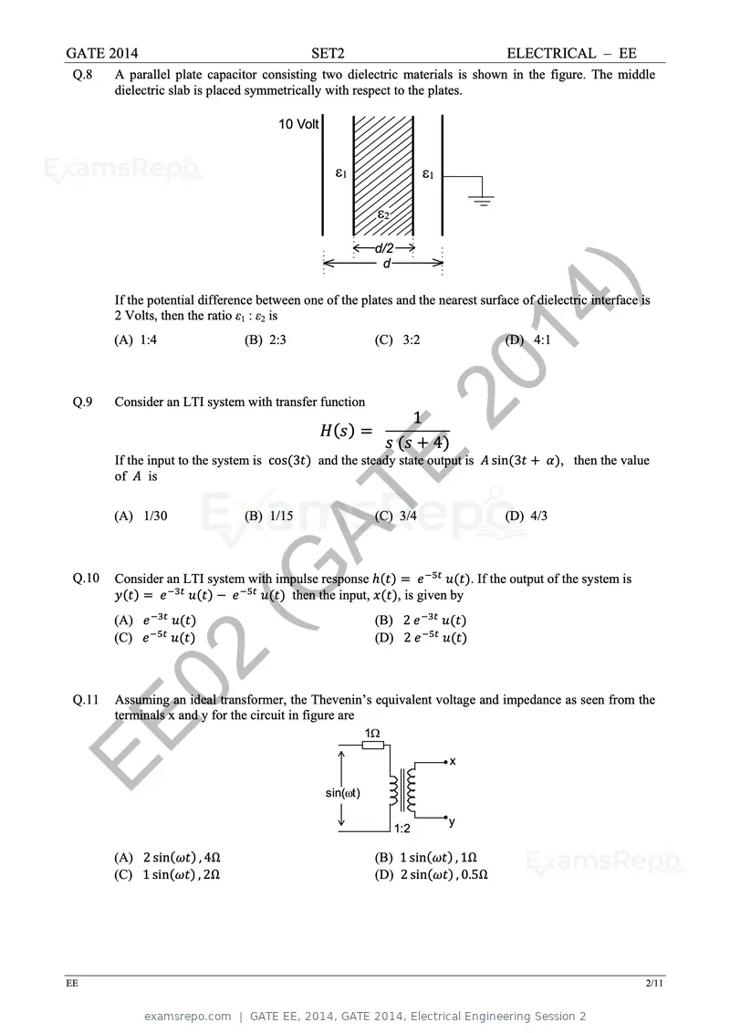
Text of page 32
GATE 2014 SET2 ELECTRICAL – EE
Q.8 A parallel plate capacitor consisting two dielectric materials is shown in the figure. The middle
dielectric slab is placed symmetrically with respect to the plates.
10 Volt
d/2
d
14
If the potential difference between one of the plates and the nearest surface of dielectric interface is
2 Volts, then the ratio ε1 : ε2 is
(A) 1:4 (B) 2:3 (C) 3:2
) (D) 4:1
Q.9 Consider an LTI system with transfer function 20 1
4
If the input to the system is cos 3
of is E
and the steady state output is sin 3 , then the value
(A) 1/30
AT
(B) 1/15 (C) 3/4 (D) 4/3
Q.10
(G
Consider an LTI system with impulse response
(A)
(C)
then the input,
(B) 2
(D) 2
, is given by
. If the output of the system is
Q.11
02
Assuming an ideal transformer, the Thevenin’s equivalent voltage and impedance as seen from the
terminals x and y for the circuit in figure are
EE sin(t)
1
x
y
1:2
(A) 2 sin , 4Ω (B) 1 sin , 1Ω
(C) 1 sin , 2Ω (D) 2 sin , 0.5Ω
EE 2/11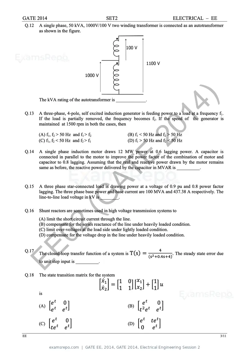
Text of page 33
GATE 2014                                    SET2                                ELECTRICAL – EE
 Q.12   A single phase, 50 kVA, 1000V/100 V two winding transformer is connected as an autotransformer
        as shown in the figure.


 Q.13
        The kVA rating of the autotransformer is _____________.
                                                                              14 )
        A three-phase, 4-pole, self excited induction generator is feeding power to a load at a frequency f1.
        If the load is partially removed, the frequency becomes f2. If the speed of the generator is
        maintained at 1500 rpm in both the cases, then

        (A) f1, f2 > 50 Hz and f1 > f2
        (C) f1, f2 < 50 Hz and f2 > f1
                                                               20
                                                         (B) f1 < 50 Hz and f2 > 50 Hz
                                                         (D) f1 > 50 Hz and f2 < 50 Hz

 Q.14   A single phase induction motor draws 12 MW power at 0.6 lagging power. A capacitor is

                                                     E
        connected in parallel to the motor to improve the power factor of the combination of motor and
        capacitor to 0.8 lagging. Assuming that the real and reactive power drawn by the motor remains
        same as before, the reactive power delivered by the capacitor in MVAR is __________.


 Q.15
                                         AT
        A three phase star-connected load is drawing power at a voltage of 0.9 pu and 0.8 power factor
        lagging. The three phase base power and base current are 100 MVA and 437.38 A respectively. The


 Q.16
                           (G
        line-to-line load voltage in kV is ________.

        Shunt reactors are sometimes used in high voltage transmission systems to
        (A) limit the short circuit current through the line.
        (B) compensate for the series reactance of the line under heavily loaded condition.

         02
        (C) limit over-voltages at the load side under lightly loaded condition.
        (D) compensate for the voltage drop in the line under heavily loaded condition.


EE
 Q.17
        The closed-loop transfer function of a system is T s
        to unit step input is __________.
                                                                          .
                                                                                . The steady state error due


 Q.18   The state transition matrix for the system
                                                     1   0            1
                                                     1   1            1
        is

        (A)
                      0                                  (B)
                                                                          0


        (C)
                       0                                 (D)
                                                                0
EE                                                                                                         3/11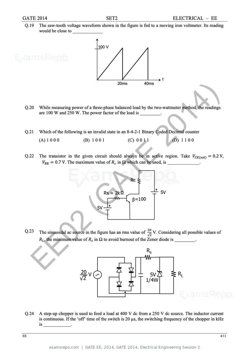
Text of page 34
GATE 2014                                     SET2                                 ELECTRICAL – EE
 Q.19   The saw-tooth voltage waveform shown in the figure is fed to a moving iron voltmeter. Its reading
        would be close to _____________


                                        100 V


                                                                              t
                                                   20ms           40ms


 Q.20                                                                        14
        While measuring power of a three-phase balanced load by the two-wattmeter method, the readings
        are 100 W and 250 W. The power factor of the load is _________.
                                                                                )
 Q.21
                                                               20
        Which of the following is an invalid state in an 8-4-2-1 Binary Coded Decimal counter
        (A) 1 0 0 0             (B) 1 0 0 1               (C) 0 0 1 1              (D) 1 1 0 0


 Q.22
                                                     E
        The transistor in the given circuit should always be in active region. Take
                0.7 V. The maximum value of     in Ω which can be used, is ______________.
                                                                                                         0.2 V,


                                     AT
                        (G
 Q.23
         02
        The sinusoidal ac source in the figure has an rms value of
          , the minimum value of
                                                                     √
                                                                         V. Considering all possible values of
                                      in Ω to avoid burnout of the Zener diode is _________.


EE
 Q.24   A step-up chopper is used to feed a load at 400 V dc from a 250 V dc source. The inductor current
        is continuous. If the ‘off’ time of the switch is 20 µs, the switching frequency of the chopper in kHz
        is ____________.

EE                                                                                                           4/11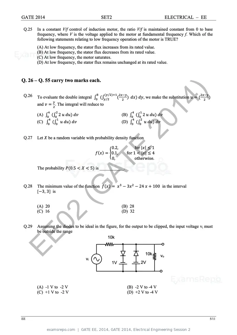
Text of page 35
GATE 2014                                     SET2                                            ELECTRICAL – EE

 Q.25   In a constant V/f control of induction motor, the ratio V/f is maintained constant from 0 to base
        frequency, where V is the voltage applied to the motor at fundamental frequency f. Which of the
        following statements relating to low frequency operation of the motor is TRUE?
        (A) At low frequency, the stator flux increases from its rated value.
        (B) At low frequency, the stator flux decreases from its rated value.
        (C) At low frequency, the motor saturates.
        (D) At low frequency, the stator flux remains unchanged at its rated value.


Q. 26 – Q. 55 carry two marks each.

 Q.26   To evaluate the double integral
        and

        (A)
                  . The integral will reduce to

                    2
                                                  ⁄
                                                      ⁄


                                                                 (B)
                                                                                     14
                                                                           , we make the substitution


                                                                           2            )
 Q.27
        (C)


        Let
                                                                 (D)


              be a random variable with probability density function
                                                                       20
                                                          E
                                                          0.2,
                                                          0.1,
                                                          0,
                                                                        for | | 1
                                                                   for 1 | | 4
                                                                        otherwise.

        The probability    0.5
                                     AT  5 is ___________.


 Q.28

                          (G
        The minimum value of the function
        [ 3, 3] is


        (A) 20
                                                                   3


                                                                 (B) 28
                                                                          24         100 in the interval


        (C) 16                                                   (D) 32


 Q.29
         02
        Assuming the diodes to be ideal in the figure, for the output to be clipped, the input voltage vi must
        be outside the range


EE                                  vi
                                                10k


                                                                               10k       vo
                                                          1V              2V


        (A) -1 V to -2 V                                           (B) -2 V to -4 V
        (C) +1 V to -2 V                                           (D) +2 V to -4 V


EE                                                                                                              5/11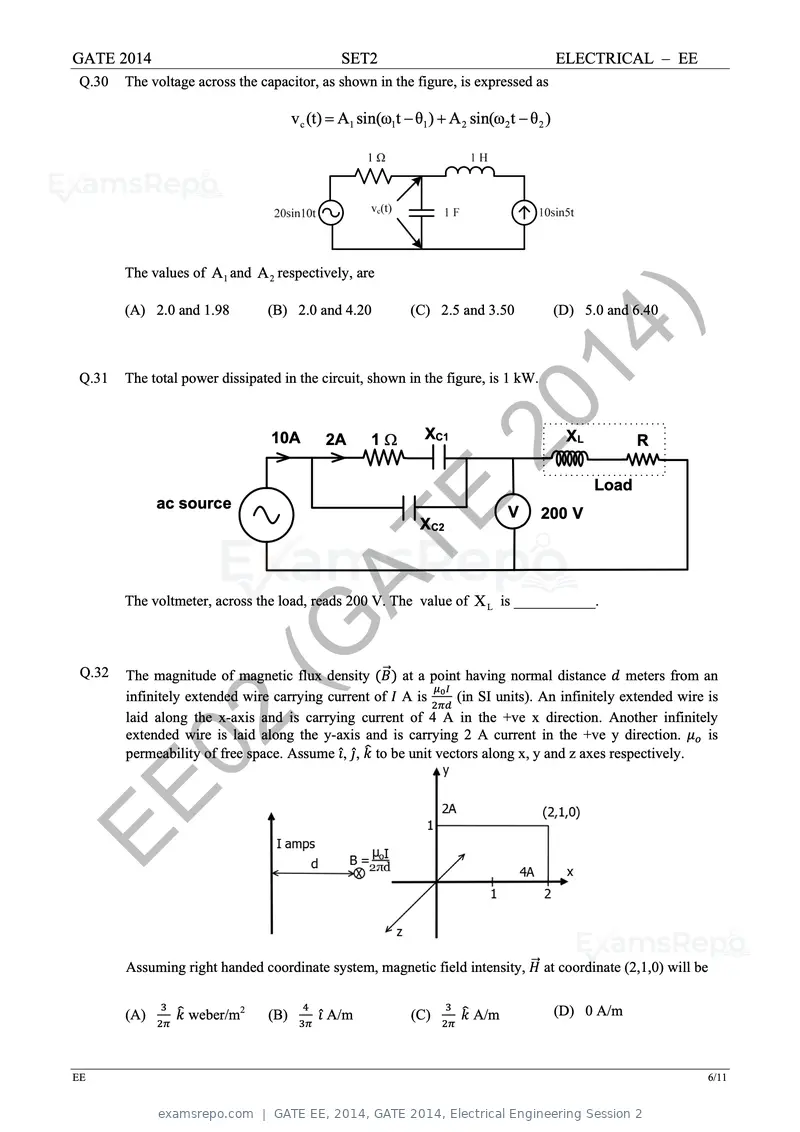
Text of page 36
GATE 2014 SET2 ELECTRICAL – EE
Q.30 The voltage across the capacitor, as shown in the figure, is expressed as
vc (t) A1 sin(ω1t θ1 ) A 2 sin(ω2 t θ 2 )
The values of A1 and A 2 respectively, are
(A) 2.0 and 1.98 (B) 2.0 and 4.20 (C) 2.5 and 3.50 (D) 5.0 and 6.40
Q.31 The total power dissipated in the circuit, shown in the figure, is 1 kW.
14 )
10A 2A 1 XC120 XL R
Load
ac source
E XC2
V 200 V
AT
The voltmeter, across the load, reads 200 V. The value of X L is ___________.
Q.32
(G
The magnitude of magnetic flux density at a point having normal distance meters from an
infinitely extended wire carrying current of A is (in SI units). An infinitely extended wire is
laid along the x-axis and is carrying current of 4 A in the +ve x direction. Another infinitely
02
extended wire is laid along the y-axis and is carrying 2 A current in the +ve y direction.
permeability of free space. Assume ̂, ̂, to be unit vectors along x, y and z axes respectively.
is
EE
Assuming right handed coordinate system, magnetic field intensity, at coordinate (2,1,0) will be
(A) weber/m2 (B) ̂ A/m (C) A/m (D) 0 A/m
EE 6/11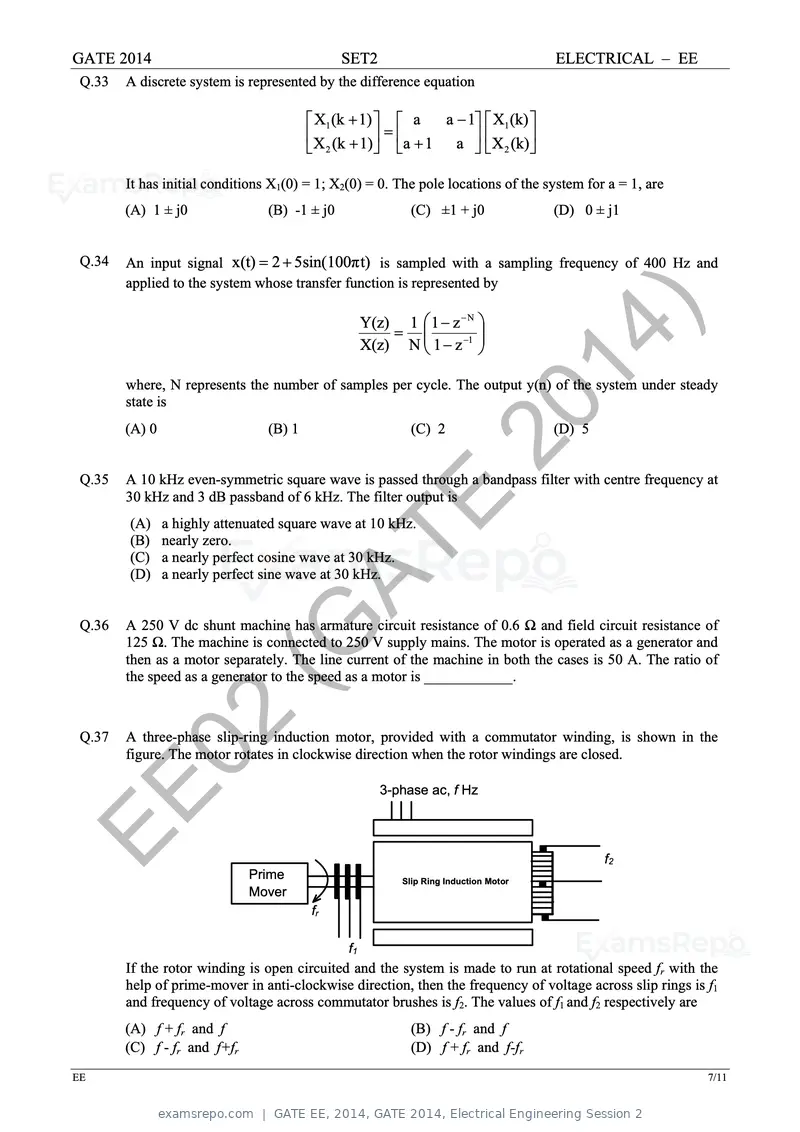
Text of page 37
GATE 2014 SET2 ELECTRICAL – EE
Q.33 A discrete system is represented by the difference equation
X1 (k 1) a a 1 X1 (k)
X (k 1) a 1 a X (k)
2 2
It has initial conditions X1(0) = 1; X2(0) = 0. The pole locations of the system for a = 1, are
(A) 1 ± j0 (B) -1 ± j0 (C) ±1 + j0 (D) 0 ± j1
Q.34 An input signal x(t) 2 5sin(100π t) is sampled with a sampling frequency of 400 Hz and
applied to the system whose transfer function is represented by
Y(z) 1 1 z N
X(z) N 1 z 1 14 )
where, N represents the number of samples per cycle. The output y(n) of the system under steady
state is
Q.35
(A) 0 (B) 1 (C) 2
20 (D) 5
A 10 kHz even-symmetric square wave is passed through a bandpass filter with centre frequency at
30 kHz and 3 dB passband of 6 kHz. The filter output is
(A)
(B)
E
a highly attenuated square wave at 10 kHz.
nearly zero.
(C)
(D) AT
a nearly perfect cosine wave at 30 kHz.
a nearly perfect sine wave at 30 kHz.
Q.36 A 250 V dc shunt machine has armature circuit resistance of 0.6 Ω and field circuit resistance of
(G
125 Ω. The machine is connected to 250 V supply mains. The motor is operated as a generator and
then as a motor separately. The line current of the machine in both the cases is 50 A. The ratio of
the speed as a generator to the speed as a motor is ____________.
Q.37
02
A three-phase slip-ring induction motor, provided with a commutator winding, is shown in the
figure. The motor rotates in clockwise direction when the rotor windings are closed.
EE Prime
3-phase ac, f Hz
f2
Slip Ring Induction Motor
Mover
fr
f1
If the rotor winding is open circuited and the system is made to run at rotational speed fr with the
help of prime-mover in anti-clockwise direction, then the frequency of voltage across slip rings is f1
and frequency of voltage across commutator brushes is f2. The values of f1 and f2 respectively are
(A) f + fr and f (B) f - fr and f
(C) f - fr and f+fr (D) f + fr and f-fr
EE 7/11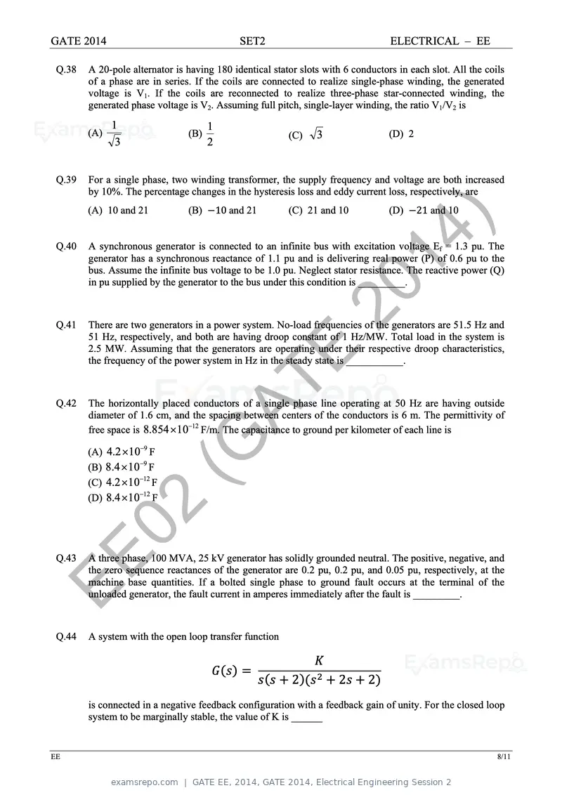
Text of page 38
GATE 2014 SET2 ELECTRICAL – EE
Q.38 A 20-pole alternator is having 180 identical stator slots with 6 conductors in each slot. All the coils
of a phase are in series. If the coils are connected to realize single-phase winding, the generated
voltage is V1. If the coils are reconnected to realize three-phase star-connected winding, the
generated phase voltage is V2. Assuming full pitch, single-layer winding, the ratio V1/V2 is
1 1
(A) (B) (C) 3 (D) 2
3 2
Q.39 For a single phase, two winding transformer, the supply frequency and voltage are both increased
by 10%. The percentage changes in the hysteresis loss and eddy current loss, respectively, are
(A) 10 and 21 (B) 10 and 21 (C) 21 and 10 (D) 21 and 10
Q.40 14 )
A synchronous generator is connected to an infinite bus with excitation voltage Ef = 1.3 pu. The
generator has a synchronous reactance of 1.1 pu and is delivering real power (P) of 0.6 pu to the
bus. Assume the infinite bus voltage to be 1.0 pu. Neglect stator resistance. The reactive power (Q)
in pu supplied by the generator to the bus under this condition is _________.
Q.41
20
There are two generators in a power system. No-load frequencies of the generators are 51.5 Hz and
51 Hz, respectively, and both are having droop constant of 1 Hz/MW. Total load in the system is
2.5 MW. Assuming that the generators are operating under their respective droop characteristics,
E
the frequency of the power system in Hz in the steady state is ___________.
Q.42 AT
The horizontally placed conductors of a single phase line operating at 50 Hz are having outside
diameter of 1.6 cm, and the spacing between centers of the conductors is 6 m. The permittivity of
free space is 8.854 1012 F/m. The capacitance to ground per kilometer of each line is
(A) 4.2 109 F
(B) 8.4 10 9 F
(C) 4.2 1012 F
(G
(D) 8.4 1012 F
02
EE
Q.43 A three phase, 100 MVA, 25 kV generator has solidly grounded neutral. The positive, negative, and
the zero sequence reactances of the generator are 0.2 pu, 0.2 pu, and 0.05 pu, respectively, at the
machine base quantities. If a bolted single phase to ground fault occurs at the terminal of the
unloaded generator, the fault current in amperes immediately after the fault is _________.
Q.44 A system with the open loop transfer function
2 2 2
is connected in a negative feedback configuration with a feedback gain of unity. For the closed loop
system to be marginally stable, the value of K is ______
EE 8/11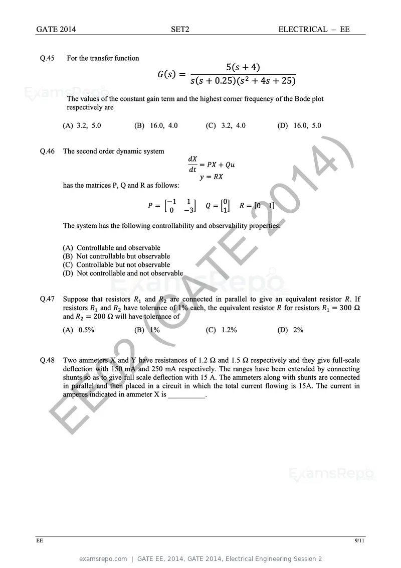
Text of page 39
GATE 2014                                   SET2                                 ELECTRICAL – EE


 Q.45    For the transfer function
                                                              5        4
                                                           0.25            4         25
         The values of the constant gain term and the highest corner frequency of the Bode plot
         respectively are

        (A) 3.2, 5.0            (B) 16.0, 4.0           (C) 3.2, 4.0             (D) 16.0, 5.0


 Q.46   The second order dynamic system


        has the matrices P, Q and R as follows:
                                                                           14 )
                                             1    1           0
                                            0      3
                                                              20
                                                              1
                                                                           0 1

        The system has the following controllability and observability properties:

        (A) Controllable and observable
        (B) Not controllable but observable
        (C) Controllable but not observable
                                                   E
 Q.47
                                     AT
        (D) Not controllable and not observable


        Suppose that resistors
        resistors   and
                                   and     are connected in parallel to give an equivalent resistor . If
                            have tolerance of 1% each, the equivalent resistor for resistors      300 Ω
        and
        (A) 0.5%        (G
                  200 Ω will have tolerance of
                                (B) 1%                  (C) 1.2%                 (D) 2%


 Q.48   Two ammeters X and Y have resistances of 1.2 Ω and 1.5 Ω respectively and they give full-scale

         02
        deflection with 150 mA and 250 mA respectively. The ranges have been extended by connecting
        shunts so as to give full scale deflection with 15 A. The ammeters along with shunts are connected
        in parallel and then placed in a circuit in which the total current flowing is 15A. The current in
        amperes indicated in ammeter X is __________.

EE

EE                                                                                                      9/11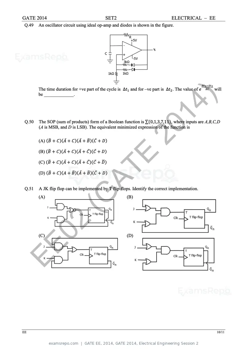
Text of page 40
GATE 2014                                                  SET2                         ELECTRICAL – EE
 Q.49   An oscillator circuit using ideal op-amp and diodes is shown in the figure.


                                                                                                          ∆
        The time duration for +ve part of the cycle is ∆           and for –ve part is ∆ . The value of       will
        be _____________.

                                                                                  14 )
 Q.50   The SOP (sum of products) form of a Boolean function is ∑ 0,1,3,7,11 , where inputs are A,B,C,D

                                                                        20
        (A is MSB, and D is LSB). The equivalent minimized expression of the function is


        (A)                ̅       ̅               ̅

        (B)            ̅       ̅           ̅   ̅

        (C)            ̅       ̅           ̅   ̅                  E
 Q.51
        (D)                            ̅
                                               AT      ̅


        A JK flip flop can be implemented by T flip-flops. Identify the correct implementation.
        (A)
                               (G                                 (B)


         02
        (C)                                                       (D)


EE

EE                                                                                                             10/11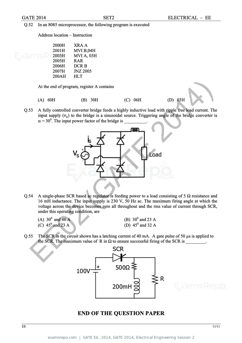
Text of page 41
GATE 2014 SET2 ELECTRICAL – EE
Q.52 In an 8085 microprocessor, the following program is executed
Address location – Instruction
2000H XRA A
2001H MVI B,04H
2003H MVI A, 03H
2005H RAR
2006H DCR B
2007H JNZ 2005
200AH HLT
At the end of program, register A contains
Q.53
(A) 60H (B) 30H (C) 06H
14 )
(D) 03H
A fully controlled converter bridge feeds a highly inductive load with ripple free load current. The
input supply (v ) to the bridge is a sinusoidal source. Triggering angle of the bridge converter is
= 300. The input power factor of the bridge is __________.
20
E
AT
Q.54
(G
A single-phase SCR based ac regulator is feeding power to a load consisting of 5 Ω resistance and
16 mH inductance. The input supply is 230 V, 50 Hz ac. The maximum firing angle at which the
voltage across the device becomes zero all throughout and the rms value of current through SCR,
under this operating condition, are
Q.55
02
(A) 300 and 46 A
(C) 450 and 23 A
(B) 300 and 23 A
(D) 450 and 32 A
The SCR in the circuit shown has a latching current of 40 mA. A gate pulse of 50 µs is applied to
EE the SCR. The maximum value of R in Ω to ensure successful firing of the SCR is _________.
END OF THE QUESTION PAPER
EE 11/11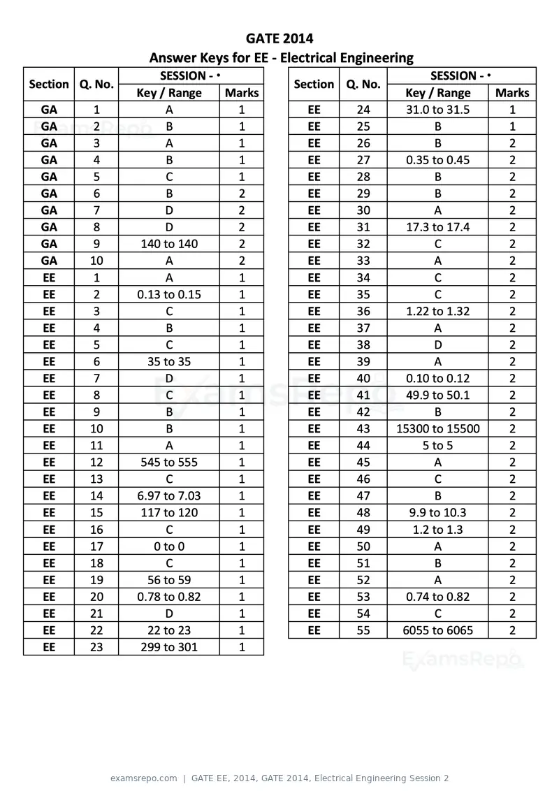
Text of page 42
GATE 2014
                   Answer Keys for EE ‐ Electrical Engineering
                     SESSION ‐ Ϯ                                 SESSION ‐ Ϯ
Section Q. No.                            Section Q. No.
                 Key / Range     Marks                      Key / Range      Marks
 GA        1          A           1         EE      24       31.0 to 31.5     1
 GA        2          B           1         EE      25            B           1
 GA        3          A           1         EE      26            B           2
 GA        4          B           1         EE      27       0.35 to 0.45     2
 GA        5           C          1         EE      28            B           2
 GA        6          B           2         EE      29            B           2
 GA        7          D           2         EE      30            A           2
 GA        8          D           2         EE      31       17.3 to 17.4     2
 GA        9      140 to 140      2         EE      32             C          2
 GA       10          A           2         EE      33            A           2
 EE        1          A           1         EE      34             C          2
 EE        2     0.13 to 0.15     1         EE      35             C          2
 EE        3           C          1         EE      36       1.22 to 1.32     2
 EE        4          B           1         EE      37            A           2
 EE        5           C          1         EE      38            D           2
 EE        6       35 to 35       1         EE      39            A           2
 EE        7          D           1         EE      40       0.10 to 0.12     2
 EE        8           C          1         EE      41       49.9 to 50.1     2
 EE        9          B           1         EE      42            B           2
 EE       10          B           1         EE      43     15300 to 15500     2
 EE       11          A           1         EE      44          5 to 5        2
 EE       12      545 to 555      1         EE      45            A           2
 EE       13           C          1         EE      46             C          2
 EE       14     6.97 to 7.03     1         EE      47            B           2
 EE       15      117 to 120      1         EE      48       9.9 to 10.3      2
 EE       16           C          1         EE      49        1.2 to 1.3      2
 EE       17        0 to 0        1         EE      50            A           2
 EE       18           C          1         EE      51            B           2
 EE       19       56 to 59       1         EE      52            A           2
 EE       20     0.78 to 0.82     1         EE      53       0.74 to 0.82     2
 EE       21          D           1         EE      54             C          2
 EE       22       22 to 23       1         EE      55      6055 to 6065      2
 EE       23      299 to 301      1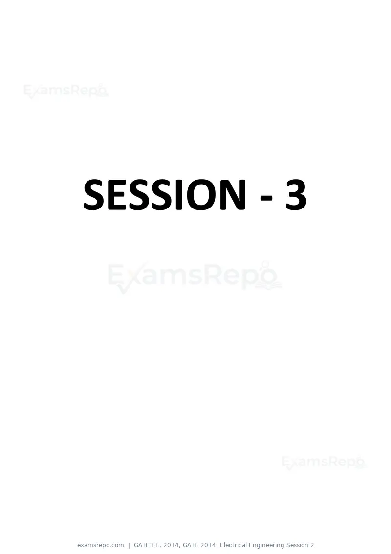
Text of page 43
SESSION - 3

Text of page 44
GATE 2014: General Instructions during Examination

   1. Total duration of the GATE examination is 180 minutes.
   2. The clock will be set at the server. The countdown timer at the top right corner of
      screen will display the remaining time available for you to complete the examination.
      When the timer reaches zero, the examination will end by itself. You need not
      terminate the examination or submit your paper.
   3. Any useful data required for your paper can be viewed by clicking on the Useful
      Common Data button that appears on the screen.
   4. Use the scribble pad provided to you for any rough work. Submit the scribble pad at
      the end of the examination.
   5. You are allowed to use a non-programmable type calculator, however, sharing of
      calculators is not allowed.
   6. The Question Palette displayed on the right side of screen will show the status of
      each question using one of the following symbols:


The Marked for Review status for a question simply indicates that you would like to look at
that question again. If a question is answered, but marked for review, then the answer will
be considered for evaluation unless the status is modified by the candidate.

Navigating to a Question :

   7. To answer a question, do the following:
         a. Click on the question number in the Question Palette to go to that question
            directly.
         b. Select an answer for a multiple choice type question by clicking on the bubble
            placed before the 4 choices, namely A, B, C and D. Use the virtual numeric
            keypad to enter a number as answer for a numerical type question.
         c. Click on Save & Next to save your answer for the current question and then go
            to the next question.
         d. Click on Mark for Review & Next to save your answer for the current question
            and also mark it for review, and then go to the next question.
Text of page 45
Caution: Note that your answer for the current question will not be saved, if you navigate
to another question directly by clicking on a question number without saving the answer to
the previous question.

You can view all the questions by clicking on the Question Paper button. This feature is
provided, so that if you want you can just see the entire question paper at a glance.

Answering a Question :

   8. Procedure for answering a multiple choice (MCQ) type question:
         a. Choose one answer from the 4 options (A,B,C,D) given below the question,
            click on the bubble placed before the chosen option.
         b. To deselect your chosen answer, click on the bubble of the chosen option again
            or click on the Clear Response button.
         c. To change your chosen answer, click on the bubble of another option.
         d. To save your answer, you MUST click on the Save & Next button.

   9. Procedure for answering a numerical answer type question:
         a. To enter a number as your answer, use the virtual numerical keypad.
         b. A fraction (e.g. -0.3 or -.3) can be entered as an answer with or without '0'
             before the decimal point. As many as four decimal points, e.g. 12.5435 or
             0.003 or -932.6711 or 12.82 can be entered.
         c. To clear your answer, click on the Clear Response button.
         d. To save your answer, you MUST click on the Save & Next button
   10. To mark a question for review, click on the Mark for Review & Next button. If an
      answer is selected (for MCQ) or entered (for numerical answer type) for a question
      that is Marked for Review, that answer will be considered in the evaluation unless
      the status is modified by the candidate.

   11. To change your answer to a question that has already been answered, first select
      that question for answering and then follow the procedure for answering that type of
      question.
   12. Note that ONLY Questions for which answers are saved or marked for review after
      answering will be considered for evaluation.


      Choosing a Section :

   13. Sections in this question paper are displayed on the top bar of the screen. Questions
      in a Section can be viewed by clicking on the name of that Section. The Section you
      are currently viewing will be highlighted.
   14. A checkbox is displayed for every optional Section, if any, in the Question Paper. To
      select the optional Section for answering, click on the checkbox for that Section.
   15. If the checkbox for an optional Section is not selected, the Save & Next button and
      the Mark for Review & Next button will NOT be enabled for that Section. You will
Text of page 46
only be able to see questions in this Section, but you will not be able to answer
      questions in the Section.
   16. After clicking the Save & Next button for the last question in a Section, you will
      automatically be taken to the first question of the next Section in sequence.
   17. You can move the mouse cursor over the name of a Section to view the answering
      status for that Section.


Changing the Optional Section :

   18. After answering the chosen optional Section, partially or completely, you can change
      the optional Section by selecting the checkbox for a new Section that you want to
      attempt. A warning message will appear along with a table showing the number of
      questions answered in each of the previously chosen optional Sections and a
      checkbox against each of these Sections. Click on a checkbox against a Section that
      you want to reset and then click on the RESET button. Note that RESETTING a Section
      will DELETE all the answers for questions in that Section. Hence, if you think that you
      may want to select this Section again later, you will have to note down your answers
      for questions in that Section. If you do not want to reset the Section and want to
      continue answering the previously chosen optional Section, then click on the BACK
      button.

   19. If you deselect the checkbox for an optional Section in the top bar, the following
      warning message will appear: "Deselecting the checkbox will DELETE all the answers
      for questions in this Section. Do you want to deselect this Section?” If you want to
      deselect, click on the RESET button. If you do not want to deselect, click on the BACK
      button.

   20. You can shuffle between different Sections or change the optional Sections any
      number of times.
Text of page 47
GATE 2014 Examination
                                      EE: Electrical Engineering
Duration: 180 minutes                                                                        Maximum Marks: 100

Read the following instructions carefully.

    1. To login, enter your Registration Number and password provided to you. Kindly go through the various
       symbols used in the test and understand their meaning before you start the examination.
    2. Once you login and after the start of the examination, you can view all the questions in the question
       paper, by clicking on the View All Questions button in the screen.
    3. This question paper consists of 2 sections, General Aptitude (GA) for 15 marks and the subject
       specific GATE paper for 85 marks. Both these sections are compulsory.
       The GA section consists of 10 questions. Question numbers 1 to 5 are of 1-mark each, while question
       numbers 6 to 10 are of 2-mark each.
       The subject specific GATE paper section consists of 55 questions, out of which question numbers 1 to
       25 are of 1-mark each, while question numbers 26 to 55 are of 2-mark each.
    4. Depending upon the GATE paper, there may be useful common data that may be required for
       answering the questions. If the paper has such useful data, the same can be viewed by clicking on the
       Useful Common Data button that appears at the top, right hand side of the screen.
    5. The computer allotted to you at the examination center runs specialized software that permits only one
        answer to be selected for multiple-choice questions using a mouse and to enter a suitable number for
        the numerical answer type questions using the virtual keyboard and mouse.
    6. Your answers shall be updated and saved on a server periodically and also at the end of the
        examination. The examination will stop automatically at the end of 180 minutes.
    7. In each paper a candidate can answer a total of 65 questions carrying 100 marks.
    8. The question paper may consist of questions of multiple choice type (MCQ) and numerical answer
        type.
    9. Multiple choice type questions will have four choices against A, B, C, D, out of which only ONE is the
        correct answer. The candidate has to choose the correct answer by clicking on the bubble (⃝) placed
        before the choice.
    10. For numerical answer type questions, each question will have a numerical answer and there will not be
        any choices. For these questions, the answer should be enteredby using the virtual keyboard that
        appears on the monitor and the mouse.
    11. All questions that are not attempted will result in zero marks. However, wrong answers for multiple
        choice type questions (MCQ) will result in NEGATIVE marks. For all MCQ questions a wrong
        answer will result in deduction of⅓ marks for a 1-mark question and ⅔ marks for a 2-mark question.
    12. There is NO NEGATIVE MARKING for questions of NUMERICAL ANSWER TYPE.
    13. Non-programmable type Calculator is allowed. Charts, graph sheets, and mathematical tables are NOT
        allowed in the Examination Hall. You must use the Scribble pad provided to you at the examination
        centre for all your rough work. The Scribble Pad has to be returned at the end of the examination.

    Declaration by the candidate:

    “I have read and understood all the above instructions. I have also read and understood clearly the
    instructions given on the admit card and shall follow the same. I also understand that in case I am found to
    violate any of these instructions, my candidature is liable to be cancelled. I also confirm that at the start of
    the examination all the computer hardware allotted to me are in proper working condition”.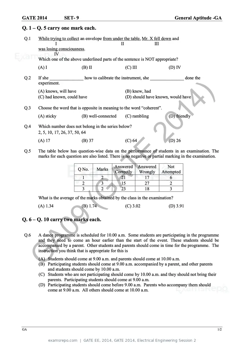
Text of page 48
GATE 2014            SET- 9                                                         General Aptitude -GA

Q. 1 – Q. 5 carry one mark each.
Q.1    While trying to collect an envelope from under the table, Mr. X fell down and
                 I                                  II                 III
       was losing consciousness.
                IV
       Which one of the above underlined parts of the sentence is NOT appropriate?
      (A) I                    (B) II                  (C) III                 (D) IV

Q.2    If she _______________ how to calibrate the instrument, she _______________ done the
       experiment.
      (A) knows, will have                             (B) knew, had


Q.3
      (C) had known, could have

                                                             20
                                                       (D) should have known, would have

       Choose the word that is opposite in meaning to the word “coherent”.
      (A) sticky               (B) well-connected
                                                               14
                                                       (C) rambling            (D) friendly

Q.4    Which number does not belong in the series below?
       2, 5, 10, 17, 26, 37, 50, 64
      (A) 17                   (B) 37                  (C) 64
                                                                  )            (D) 26

Q.5    The table below has question-wise data on the performance of students in an examination. The


                                        AT
       marks for each question are also listed. There is no negative or partial marking in the examination.

                                                 Answered        Answered      Not
                            Q No.
                               1
                               2
                               3
                                           E
                                        Marks
                                          2
                                          3
                                          2
                                                 Correctly
                                                    21
                                                    15
                                                    23
                                                                 Wrongly
                                                                    17
                                                                    27
                                                                    18
                                                                            Attempted
                                                                                6
                                                                                2
                                                                                3

                        (G
       What is the average of the marks obtained by the class in the examination?
      (A) 1.34                 (B) 1.74                (C) 3.02                (D) 3.91


               9
Q. 6 – Q. 10 carry two marks each.

Q.6
     A0A dance programme is scheduled for 10.00 a.m. Some students are participating in the programme
       and they need to come an hour earlier than the start of the event. These students should be
       accompanied by a parent. Other students and parents should come in time for the programme. The
       instruction you think that is appropriate for this is

G      (A) Students should come at 9.00 a.m. and parents should come at 10.00 a.m.
       (B) Participating students should come at 9.00 a.m. accompanied by a parent, and other parents
           and students should come by 10.00 a.m.
       (C) Students who are not participating should come by 10.00 a.m. and they should not bring their
           parents. Participating students should come at 9.00 a.m.
       (D) Participating students should come before 9.00 a.m. Parents who accompany them should
           come at 9.00 a.m. All others should come at 10.00 a.m.


GA                                                                                                        1/2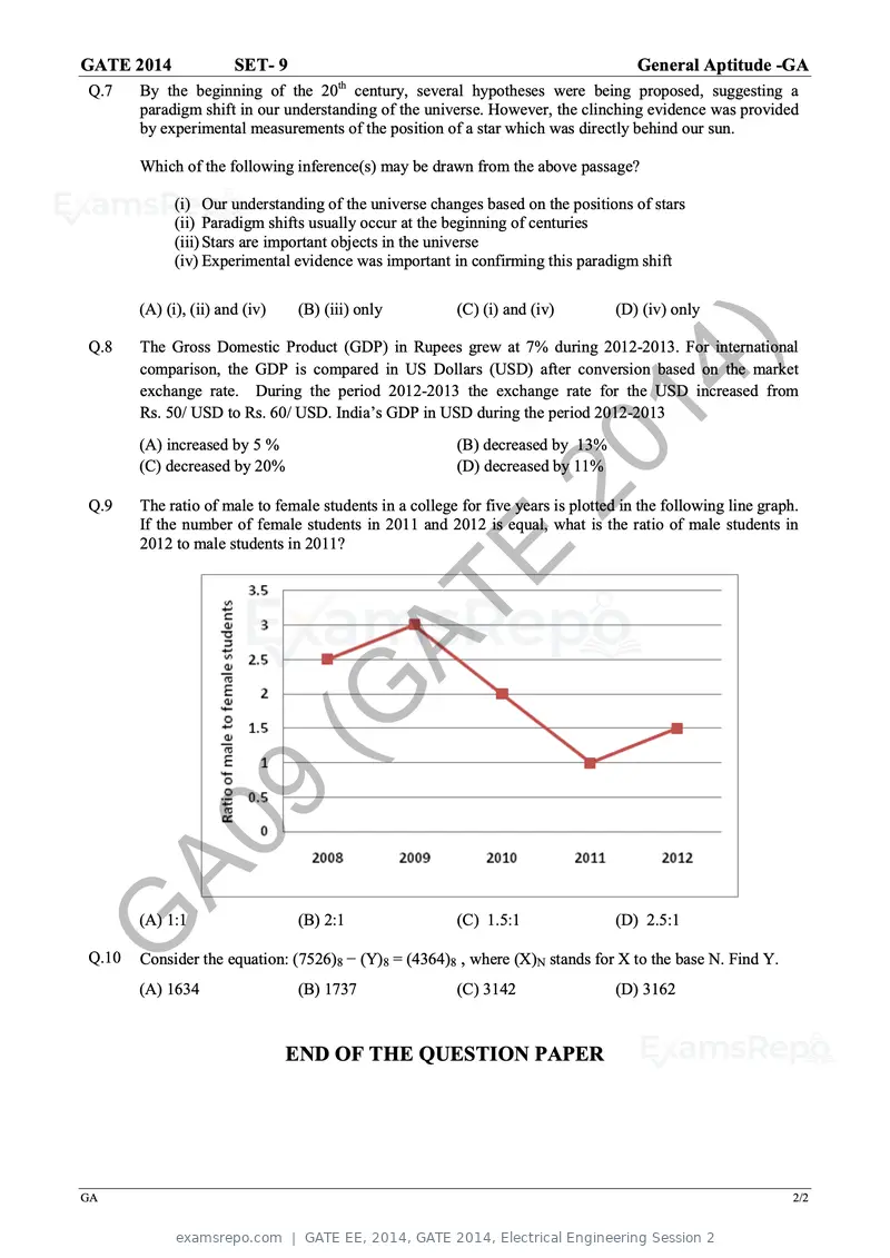
Text of page 49
GATE 2014              SET- 9                                                        General Aptitude -GA
                                      th
Q.7    By the beginning of the 20 century, several hypotheses were being proposed, suggesting a
       paradigm shift in our understanding of the universe. However, the clinching evidence was provided
       by experimental measurements of the position of a star which was directly behind our sun.

       Which of the following inference(s) may be drawn from the above passage?

             (i) Our understanding of the universe changes based on the positions of stars
             (ii) Paradigm shifts usually occur at the beginning of centuries
             (iii) Stars are important objects in the universe
             (iv) Experimental evidence was important in confirming this paradigm shift

       (A) (i), (ii) and (iv)   (B) (iii) only           (C) (i) and (iv)         (D) (iv) only

Q.8


                                                               20
       The Gross Domestic Product (GDP) in Rupees grew at 7% during 2012-2013. For international
       comparison, the GDP is compared in US Dollars (USD) after conversion based on the market
       exchange rate. During the period 2012-2013 the exchange rate for the USD increased from


                                                                 14
       Rs. 50/ USD to Rs. 60/ USD. India’s GDP in USD during the period 2012-2013


                                                                    )
       (A) increased by 5 %                              (B) decreased by 13%
       (C) decreased by 20%                              (D) decreased by 11%

Q.9    The ratio of male to female students in a college for five years is plotted in the following line graph.
       If the number of female students in 2011 and 2012 is equal, what is the ratio of male students in
       2012 to male students in 2011?


                                      AT
                                         E
                           (G
                 9
     A0
G
Q.10
       (A) 1:1                  (B) 2:1                  (C) 1.5:1                (D) 2.5:1

       Consider the equation: (7526)8 − (Y)8 = (4364)8 , where (X)N stands for X to the base N. Find Y.
       (A) 1634                 (B) 1737                 (C) 3142                 (D) 3162


                                END OF THE QUESTION PAPER


GA                                                                                                            2/2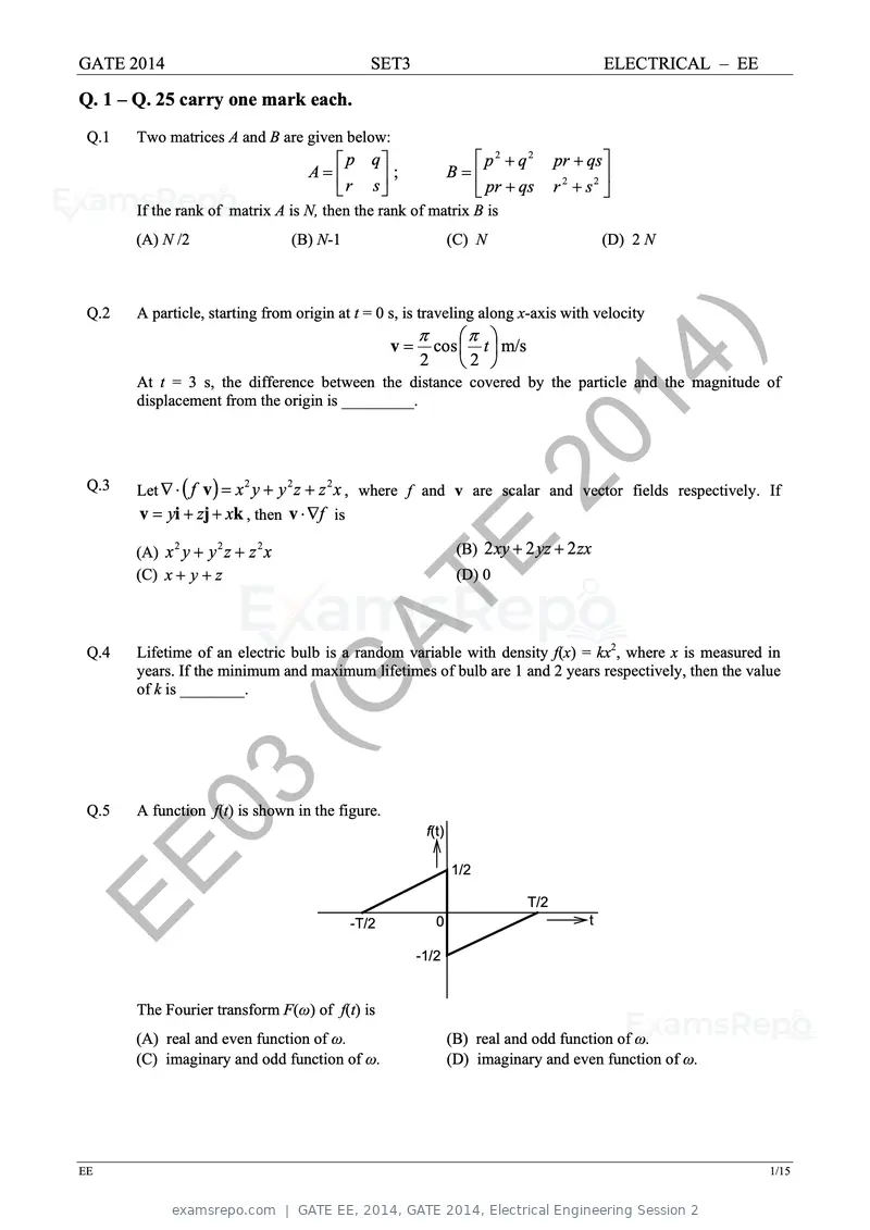
Text of page 50
GATE 2014 SET3 ELECTRICAL – EE
Q. 1 – Q. 25 carry one mark each.
Q.1 Two matrices A and B are given below:
p q p2 + q2 pr + qs
A= ; B=
r s pr + qs r 2 + s2
If the rank of matrix A is N, then the rank of matrix B is
(A) N /2 (B) N-1 (C) N (D) 2 N
Q.2 A particle, starting from origin at t = 0 s, is traveling along x-axis with velocity
π π
v=
2
20
cos t m/s
2
At t = 3 s, the difference between the distance covered by the particle and the magnitude of
displacement from the origin is _________.
14
Q.3 )
Let ∇ ⋅ ( f v ) = x y + y z + z x , where f and v are scalar and vector fields respectively. If
2 2 2
v = yi + zj + xk , then v ⋅ ∇f is
(A) x y + y z + z x
2
(C) x + y + z
2 2
E (B) 2 xy + 2 yz + 2 zx
(D) 0
(G
Q.4
AT
Lifetime of an electric bulb is a random variable with density f(x) = kx2, where x is measured in
years. If the minimum and maximum lifetimes of bulb are 1 and 2 years respectively, then the value
of k is ________.
Q.5 03
A function f(t) is shown in the figure.
f(t)
EE -T/2 0
1/2
T/2
t
-1/2
The Fourier transform F(ω) of f(t) is
(A) real and even function of ω. (B) real and odd function of ω.
(C) imaginary and odd function of ω. (D) imaginary and even function of ω.
EE 1/15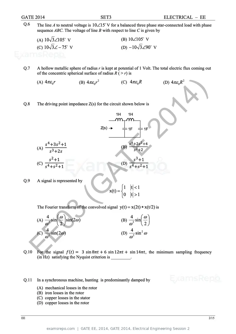
Text of page 51
GATE 2014 SET3 ELECTRICAL – EE
Q.6 The line A to neutral voltage is 10∠15 V for a balanced three phase star-connected load with phase
sequence ABC. The voltage of line B with respect to line C is given by
(A) 10 3∠105 V
(B) 10∠105 V
(C) 10 3∠ − 75 V (D) − 10 3∠90 V
Q.7 A hollow metallic sphere of radius r is kept at potential of 1 Volt. The total electric flux coming out
of the concentric spherical surface of radius R ( > r) is
(A) 4πε 0 r (B) 4πε 0 r
2
(C) 4πε 0 R (D) 4πε 0 R
2
Q.8 The driving point impedance Z(s) for the circuit shown below is
1H
20
1H
14
ss 4 +3ss 2 +1
Z(s) 1F
)
ss 4 +2ss 2 +4
1F
(A)
ss 3 +2ss
ss 2 +1
E (B)
ss 2 +2
ss 3 +1
(C)
ss 4 +ss 2 +1
(G (D)
ss 4 +ss 2 +1
Q.9 A signal is represented by
AT 1
x(t) =
0
t <1
t >1
The Fourier transform of the convolved signal y(t) = x(2t) ∗ x(t/2) is
03
(A)
ω
4
4 ω
sin sin( 2ω )
2
2
(C) 2 sin( 2ω )
(B)
ω
4
4 ω
sin
2
2
(D) 2 sin 2 ω
EE
Q.10
ω ω
For the signal ff(tt) = 3 sin 8ππππ + 6 sin 12ππππ + sin 14ππππ, the minimum sampling frequency
(in Hz) satisfying the Nyquist criterion is _________.
Q.11 In a synchronous machine, hunting is predominantly damped by
(A) mechanical losses in the rotor
(B) iron losses in the rotor
(C) copper losses in the stator
(D) copper losses in the rotor
EE 2/15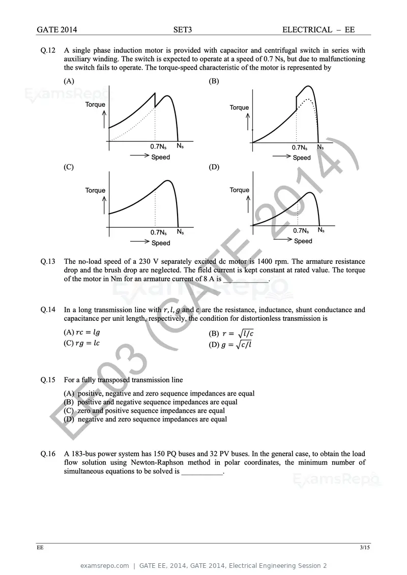
Text of page 52
GATE 2014                                     SET3                                 ELECTRICAL – EE

 Q.12   A single phase induction motor is provided with capacitor and centrifugal switch in series with
        auxiliary winding. The switch is expected to operate at a speed of 0.7 Ns, but due to malfunctioning
        the switch fails to operate. The torque-speed characteristic of the motor is represented by
        (A)                                               (B)


                Torque                                           Torque


                                     0.7Ns    Ns                                      0.7Ns    Ns
                                      Speed


                                                                20
                                                                                       Speed
        (C)                                               (D)


                Torque

                                                                  14
                                                                 Torque


                                                                    )
                                     0.7Ns    Ns                                       0.7Ns   Ns

                                      Speed                                            Speed


 Q.13                                                E
        The no-load speed of a 230 V separately excited dc motor is 1400 rpm. The armature resistance
        drop and the brush drop are neglected. The field current is kept constant at rated value. The torque


                          (G
        of the motor in Nm for an armature current of 8 A is ____________.


 Q.14

                            AT
        In a long transmission line with rr, ll, gg and cc are the resistance, inductance, shunt conductance and
        capacitance per unit length, respectively, the condition for distortionless transmission is
        (A) rrrr = llll
        (C) rrrr = llll
                                                          (B) rr = �ll/cc
                                                          (D) gg = �cc/ll


 Q.15    03
        For a fully transposed transmission line
        (A) positive, negative and zero sequence impedances are equal


EE      (B) positive and negative sequence impedances are equal
        (C) zero and positive sequence impedances are equal
        (D) negative and zero sequence impedances are equal


 Q.16   A 183-bus power system has 150 PQ buses and 32 PV buses. In the general case, to obtain the load
        flow solution using Newton-Raphson method in polar coordinates, the minimum number of
        simultaneous equations to be solved is ___________.


EE                                                                                                            3/15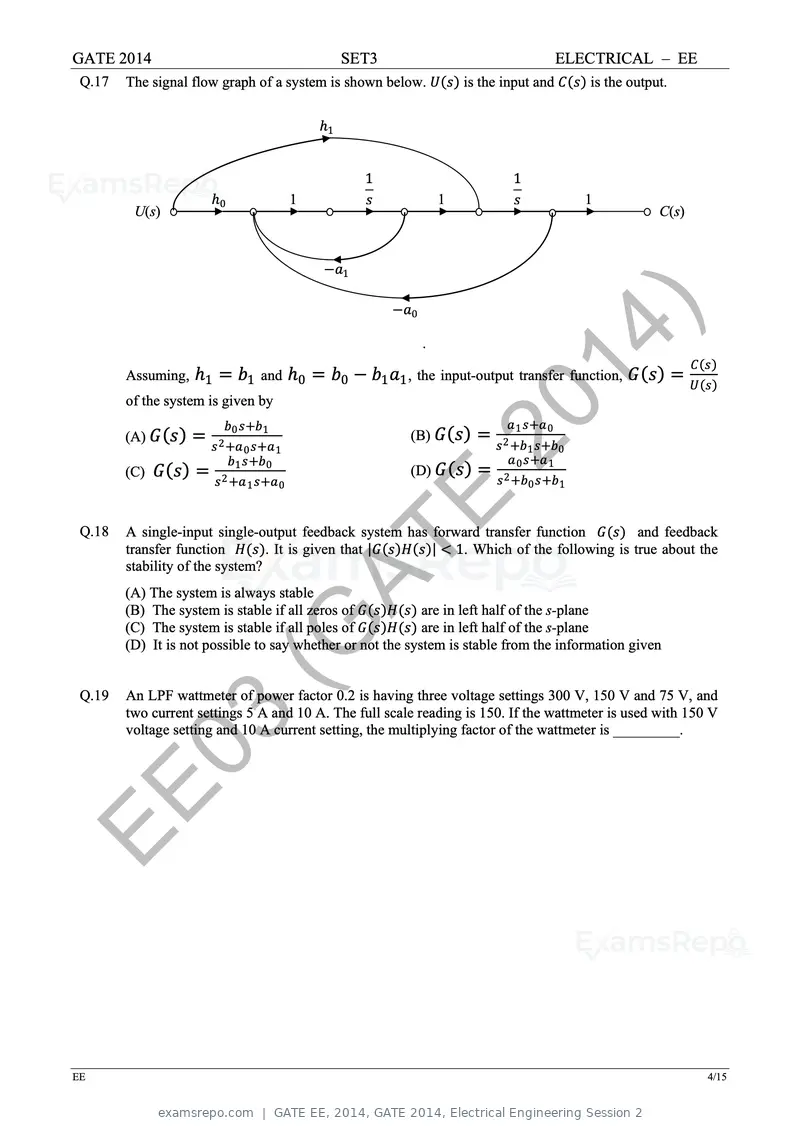
Text of page 53
GATE 2014                                             SET3                                 ELECTRICAL – EE
 Q.17   The signal flow graph of a system is shown below. UU(ss) is the input and CC(ss) is the output.

                                                 ℎ1


                                                        1                         1
                        ℎ0                   1          ss              1         ss             1
         U(s)                                                                                        C(s)


                                                 −aa1

                                                             −aa0

                                                                    .
                                                                        2014
        Assuming, ℎ1 = bb1 and ℎ0 = bb0 − bb1 aa1 , the input-output transfer function, GG (ss) =
        of the system is given by
                                                                                                            CC(ss)
                                                                                                            UU(ss)


        (A) GG (ss) =

        (C) GG (ss) =
                           bb0 ss+bb1
                        ss 2 +aa 0 ss+aa 1
                             bb1 ss+bb0
                        ss 2 +aa 1 ss+aa 0
                                                               (B) GG (ss) =

                                                               (D) GG (ss) =
                                                                            )    2
                                                                                  aa 1 ss+aa 0
                                                                               ss +bb1 ss+bb0

                                                                                 2
                                                                                  aa 0 ss+aa 1
                                                                               ss +bb0 ss+bb1


 Q.18
                                                             E
        A single-input single-output feedback system has forward transfer function GG(ss) and feedback


                           (G
        transfer function HH(ss). It is given that |GG(ss)HH(ss)| < 1. Which of the following is true about the
        stability of the system?


                             AT
        (A) The system is always stable
        (B) The system is stable if all zeros of GG(ss)HH(ss) are in left half of the s-plane
        (C) The system is stable if all poles of GG(ss)HH(ss) are in left half of the s-plane
        (D) It is not possible to say whether or not the system is stable from the information given


 Q.19   An LPF wattmeter of power factor 0.2 is having three voltage settings 300 V, 150 V and 75 V, and
        two current settings 5 A and 10 A. The full scale reading is 150. If the wattmeter is used with 150 V

         03
        voltage setting and 10 A current setting, the multiplying factor of the wattmeter is _________.


EE

EE                                                                                                             4/15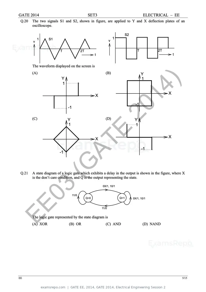
Text of page 54
GATE 2014                                        SET3                                   ELECTRICAL – EE
 Q.20   The two signals S1 and S2, shown in figure, are applied to Y and X deflection plates of an
        oscilloscope.

                                                                           S2
            1     S1                                                 1
        v                                                        v

                          T                2T                                      T          2T
                                                      t                                                t


        The waveform displayed on the screen is
        (A)                                                  (B)                       Y
                           Y                                                           1
                           1

                                                      X
                                                                     2014                          X


        (C)
                               -1

                               Y
                               1
                                                             (D)
                                                                         )       Y
                                                                                 1
                                                                                  -1


                                                      X
                                                          E                                        X


                        (G                                                             -1


                          AT
                          -1


 Q.21   A state diagram of a logic gate which exhibits a delay in the output is shown in the figure, where X
        is the don’t care condition, and Q is the output representing the state.


         03                         11/0
                                                Q=0
                                                          0X/1, 10/1


                                                                         Q=1    0X/1, 10/1


EE      The logic gate represented by the state diagram is
        (A) XOR                 (B) OR
                                                          11/0


                                                             (C) AND                   (D) NAND


EE                                                                                                         5/15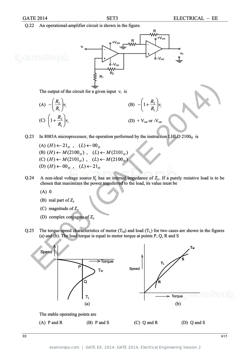
Text of page 55
GATE 2014 SET3 ELECTRICAL – EE
Q.22 An operational-amplifier circuit is shown in the figure.
R
+Vsat
+Vsat R
-
vi
-
+ vo
+ -Vsat
-Vsat
R2
R1
The output of the circuit for a given input vi is
(A) −
R2
vi
R1
(C) 1 +
R2
vi
R1
20
(B) − 1 +
14
R2
vi
R1
(D) + Vsat or -Vsat
Q.23
)
In 8085A microprocessor, the operation performed by the instruction LHLD 2100H is
(A) ( H ) ← 21H , ( L) ← 00 H
(B) ( H ) ← M (2100 H ) , ( L) ← M (2101H )
(C) ( H ) ← M (2101H ) , ( L) ← M (2100 H )
(D) ( H ) ← 00 H , ( L) ← 21H
E
Q.24
(G
A non-ideal voltage source VVss has an internal impedance of ZZss . If a purely resistive load is to be
chosen that maximizes the power transferred to the load, its value must be
(A) 0
(B) real part of ZZss
(C) magnitude of ZZss
AT
(D) complex conjugate of ZZss
Q.25
03
The torque-speed characteristics of motor (TM) and load (TL) for two cases are shown in the figures
(a) and (b). The load torque is equal to motor torque at points P, Q, R and S
EE Speed
P
Torque
TM Speed
TL
S
TM
Q R
TL Torque
(a) (b)
The stable operating points are
(A) P and R (B) P and S (C) Q and R (D) Q and S
EE 6/15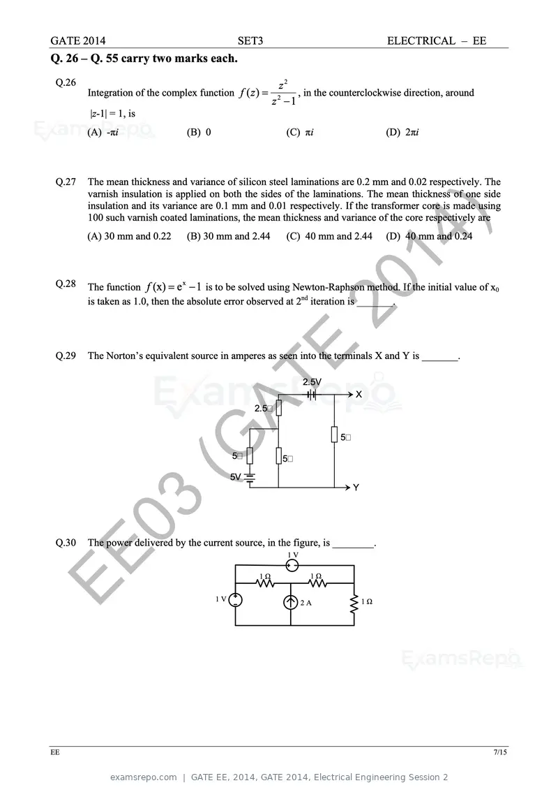
Text of page 56
GATE 2014 SET3 ELECTRICAL – EE
Q. 26 – Q. 55 carry two marks each.
Q.26 z2
Integration of the complex function f ( z ) = , in the counterclockwise direction, around
z2 −1
|z-1| = 1, is
(A) -πi (B) 0 (C) πi (D) 2πi
Q.27 The mean thickness and variance of silicon steel laminations are 0.2 mm and 0.02 respectively. The
varnish insulation is applied on both the sides of the laminations. The mean thickness of one side
insulation and its variance are 0.1 mm and 0.01 respectively. If the transformer core is made using
20
100 such varnish coated laminations, the mean thickness and variance of the core respectively are
(A) 30 mm and 0.22 (B) 30 mm and 2.44 (C) 40 mm and 2.44 (D) 40 mm and 0.24
Q.28 14)
The function f (x) = e − 1 is to be solved using Newton-Raphson method. If the initial value of x0
x
is taken as 1.0, then the absolute error observed at 2nd iteration is _______.
Q.29
E
The Norton’s equivalent source in amperes as seen into the terminals X and Y is _______.
(G 2.5
2.5V
X
AT 5
5V
5
5
Y
Q.30
03
The power delivered by the current source, in the figure, is ________.
EE 1V
1Ω
1V
1Ω
2A 1Ω
EE 7/15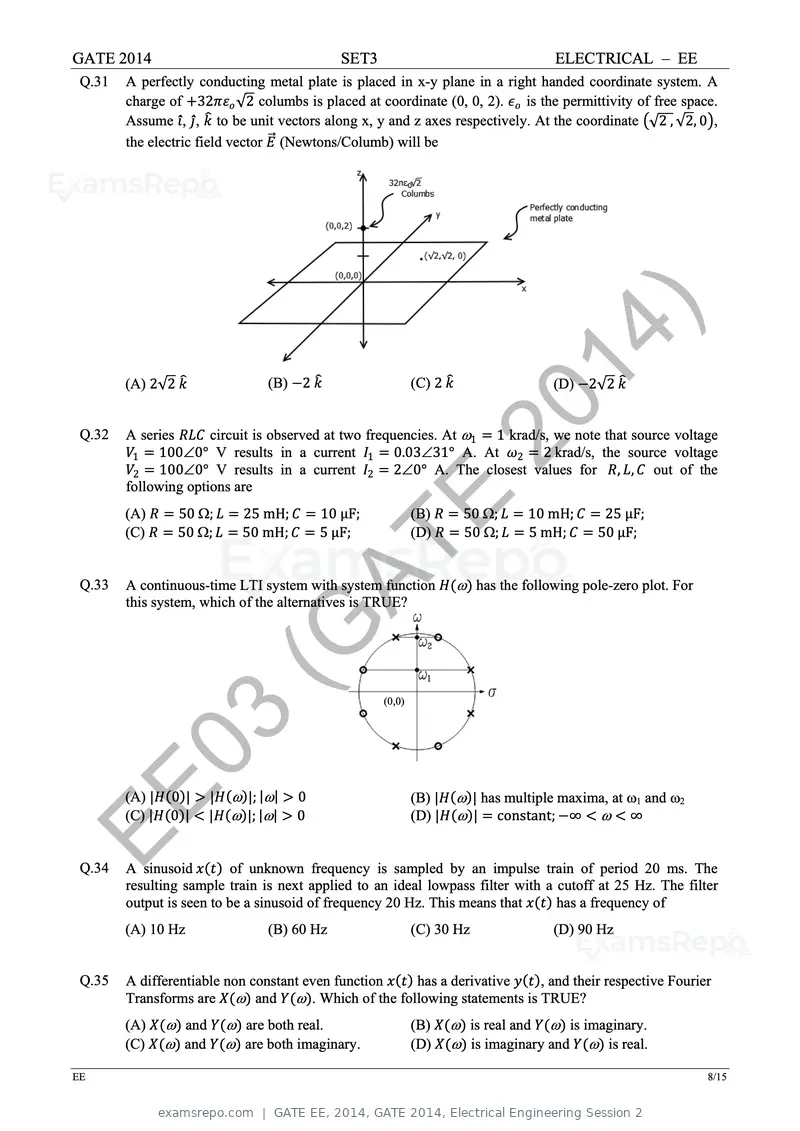
Text of page 57
GATE 2014                                     SET3                                    ELECTRICAL – EE
 Q.31   A perfectly conducting metal plate is placed in x-y plane in a right handed coordinate system. A
        charge of +32ππεεoo √2 columbs is placed at coordinate (0, 0, 2). εεoo is the permittivity of free space.
        Assume iî, jĵ, kk� to be unit vectors along x, y and z axes respectively. At the coordinate �√2 , √2, 0�,
        the electric field vector EE�⃗ (Newtons/Columb) will be


        (A) 2√2 kk�              (B) −2 kk�
                                                                    2014
                                                              (C) 2 kk�               (D) −2√2 kk�


 Q.32
                                                                        )
        A series RRRRRR circuit is observed at two frequencies. At ω1 = 1 krad/s, we note that source voltage
        VV1 = 100∠0° V results in a current II1 = 0.03∠31° A. At ωω2 = 2 krad/s, the source voltage
        VV2 = 100∠0° V results in a current II2 = 2∠0° A. The closest values for RR, LL, CC out of the
        following options are
        (A) RR = 50 Ω; LL = 25 mH; CC = 10 µF;
        (C) RR = 50 Ω; LL = 50 mH; CC = 5 µF;
                                                      E       (B) RR = 50 Ω; LL = 10 mH; CC = 25 µF;
                                                              (D) RR = 50 Ω; LL = 5 mH; CC = 50 µF;


 Q.33                    (G
        A continuous-time LTI system with system function HH(ω) has the following pole-zero plot. For


                           AT
        this system, which of the alternatives is TRUE?


                                                      (0,0)


         03
EE
 Q.34
        (A) |HH(0)| > |HH(ω)|; |ω| > 0
        (C) |HH(0)| < |HH(ω)|; |ω| > 0
                                                              (B) |HH(ω)| has multiple maxima, at ω1 and ω2
                                                              (D) |HH(ω)| = constant; −∞ < ω < ∞


        A sinusoid xx(tt) of unknown frequency is sampled by an impulse train of period 20 ms. The
        resulting sample train is next applied to an ideal lowpass filter with a cutoff at 25 Hz. The filter
        output is seen to be a sinusoid of frequency 20 Hz. This means that xx(tt) has a frequency of
        (A) 10 Hz                (B) 60 Hz                    (C) 30 Hz               (D) 90 Hz


 Q.35   A differentiable non constant even function xx(tt) has a derivative yy(tt), and their respective Fourier
        Transforms are XX(ω) and YY(ω). Which of the following statements is TRUE?
        (A) XX(ω) and YY(ω) are both real.                    (B) XX(ω) is real and YY(ω) is imaginary.
        (C) XX(ω) and YY(ω) are both imaginary.               (D) XX(ω) is imaginary and YY(ω) is real.

EE                                                                                                               8/15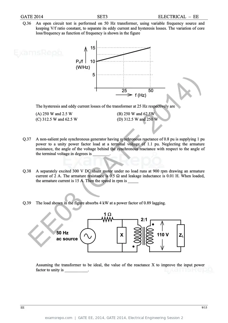
Text of page 58
GATE 2014                                    SET3                                ELECTRICAL – EE
 Q.36   An open circuit test is performed on 50 Hz transformer, using variable frequency source and
        keeping V/f ratio constant, to separate its eddy current and hysteresis losses. The variation of core
        loss/frequency as function of frequency is shown in the figure


                                        15


                               Pc/f   10
                               (W/Hz)
                                         5


                                                           25

                                                              2014
                                                                   f (Hz)
                                                                            50


        The hysteresis and eddy current losses of the transformer at 25 Hz respectively are
        (A) 250 W and 2.5 W                             (B) 250 W and 62.5W


 Q.37
        (C) 312.5 W and 62.5 W

                                                                  )
                                                        (D) 312.5 W and 250 W


        A non-salient pole synchronous generator having synchronous reactance of 0.8 pu is supplying 1 pu

                                                    E
        power to a unity power factor load at a terminal voltage of 1.1 pu. Neglecting the armature
        resistance, the angle of the voltage behind the synchronous reactance with respect to the angle of
        the terminal voltage in degrees is ________.


                        (G
 Q.38

                          AT
        A separately excited 300 V DC shunt motor under no load runs at 900 rpm drawing an armature
        current of 2 A. The armature resistance is 0.5 Ω and leakage inductance is 0.01 H. When loaded,
        the armature current is 15 A. Then the speed in rpm is _____


 Q.39   The load shown in the figure absorbs 4 kW at a power factor of 0.89 lagging.

         03                                     1Ω
                                                                      2:1


EE                  50 Hz
                    ac source
                                                          X                      110 V        ZL


        Assuming the transformer to be ideal, the value of the reactance X to improve the input power
        factor to unity is ___________.


EE                                                                                                         9/15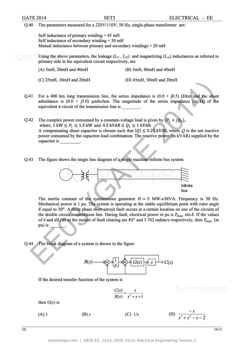
Text of page 59
GATE 2014                                       SET3                                    ELECTRICAL – EE
 Q.40   The parameters measured for a 220V/110V, 50 Hz, single-phase transformer are:

        Self inductance of primary winding = 45 mH
        Self inductance of secondary winding = 30 mH
        Mutual inductance between primary and secondary windings = 20 mH

        Using the above parameters, the leakage (Ll1 , Ll2) and magnetizing (Lm) inductances as referred to
        primary side in the equivalent circuit respectively, are
        (A) 5mH, 20mH and 40mH                                  (B) 5mH, 80mH and 40mH

        (C) 25mH, 10mH and 20mH                                 (D) 45mH, 30mH and 20mH


 Q.41


 Q.42
                                                                     20
        For a 400 km long transmission line, the series impedance is (0.0 + j0.5) Ω/km and the shunt
        admittance is (0.0 + j5.0) µmho/km. The magnitude of the series impedance (in Ω) of the
        equivalent π circuit of the transmission line is ________.


                                                                       14
        The complex power consumed by a constant-voltage load is given by (PP1 + jjQQ1 ),
         where, 1 kW ≤ PP1 ≤ 1.5 kW and 0.5 kVAR ≤ QQ1 ≤ 1 kVAR.

                                                                         )
        A compensating shunt capacitor is chosen such that |QQ| ≤ 0.25 kVAR, where Q is the net reactive
        power consumed by the capacitor-load combination. The reactive power (in kVAR) supplied by the
        capacitor is _________.


 Q.43                                                    E
        The figure shows the single line diagram of a single machine infinite bus system.


                          (G
                            AT
        The inertia constant of the synchronous generator HH = 5 MW-s/MVA. Frequency is 50 Hz.
                                                                                               Infinite
                                                                                               bus


        Mechanical power is 1 pu. The system is operating at the stable equilibrium point with rotor angle
        δδ equal to 30o . A three phase short circuit fault occurs at a certain location on one of the circuits of
        the double circuit transmission line. During fault, electrical power in pu is PPmmmmmm sin δδ. If the values
        of δ and dddd ⁄dddd at the instant of fault clearing are 45o and 3.762 radian/s respectively, then PPmmmmmm (in

         03
        pu) is _______.


EE
 Q.44   The block diagram of a system is shown in the figure


                                    R(s)        +
                                                    -
                                                        1
                                                        s
                                                            +
                                                                -
                                                                -   G(s)     s       C(s)


        If the desired transfer function of the system is

                                                        C ( s)     s
                                                               = 2
                                                        R( s) s + s + 1
        then G(s) is
                                                                                                   −s
        (A) 1                     (B) s                         (C) 1/s                 (D)
                                                                                              s + s2 − s − 2
                                                                                               3


EE                                                                                                                  10/15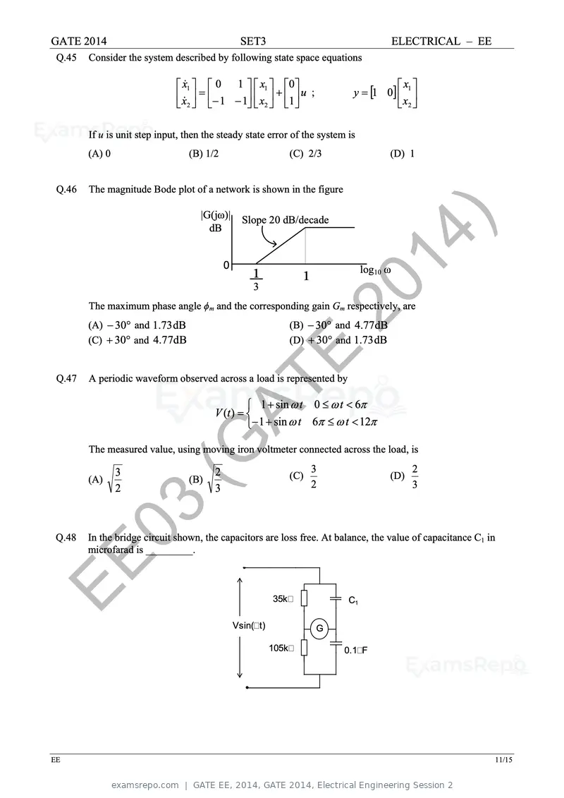
Text of page 60
GATE 2014 SET3 ELECTRICAL – EE
Q.45 Consider the system described by following state space equations
x1 0 1 x1 0 x
x = − 1 − 1 x + 1 u ; y = [1 0] 1
2 2 x2
If u is unit step input, then the steady state error of the system is
(A) 0 (B) 1/2 (C) 2/3 (D) 1
Q.46 The magnitude Bode plot of a network is shown in the figure
|G(jω)|
dB
0
Slope 20 dB/decade
1 1
2014 log10 ω
3
)
The maximum phase angle ϕm and the corresponding gain Gm respectively, are
(A) − 30° and 1.73 dB
(C) + 30° and 4.77dB
(B) − 30° and 4.77dB
(D) + 30° and 1.73 dB
Q.47
E
A periodic waveform observed across a load is represented by
(G 1 + sin ω t 0 ≤ ω t < 6π
V (t ) =
AT − 1 + sin ω t 6π ≤ ω t < 12π
The measured value, using moving iron voltmeter connected across the load, is
(A)
3
(B)
2 (C)
3
(D)
2
2 3 2 3
Q.48
03
In the bridge circuit shown, the capacitors are loss free. At balance, the value of capacitance C1 in
microfarad is _________.
EE 35k C1
Vsin(t) G
105k 0.1F
EE 11/15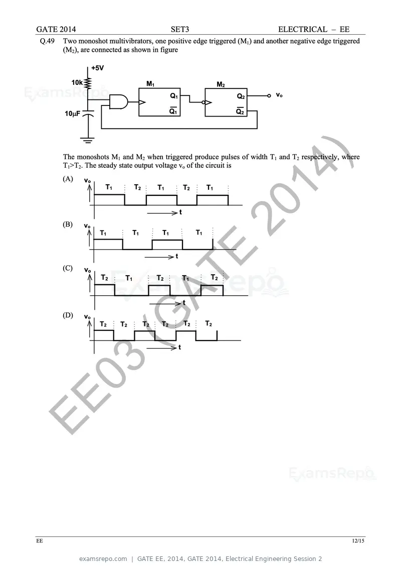
Text of page 61
GATE 2014                                              SET3                              ELECTRICAL – EE
 Q.49   Two monoshot multivibrators, one positive edge triggered (M1) and another negative edge triggered
        (M2), are connected as shown in figure

                     +5V

          10k                               M1                                 M2
                                                       Q1                           Q2   vo

        10µF                                           Q1                           Q2


                                                                                20
        The monoshots M1 and M2 when triggered produce pulses of width T1 and T2 respectively, where
        T1>T2. The steady state output voltage vo of the circuit is
        (A)     vo
                           T1         T2         T1             T2        T1

                                                                                  14
        (B)     vo
                       T1            T1           T1
                                                            t

                                                                     T1
                                                                                    )
        (C)     vo
                                                        t
                                                                     E
                       T2

                                (G
                                 T1              T2             T1         T2


        (D)     vo
                       T2       T2AT       T2     T2
                                                                t

                                                                T2        T2


                                                            t


         03
EE

EE                                                                                                         12/15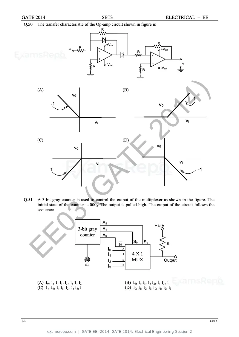
Text of page 62
GATE 2014                                                  SET3                                               ELECTRICAL – EE
 Q.50   The transfer characteristic of the Op-amp circuit shown in figure is
                                                           R


                                                               +Vsat                                  R
                             vi         R
                                                                                                          +Vsat
                                                       -                                R
                                                                                                  -
                                                       +
                                                               -Vsat                              +                   vo
                                                  R
                                                                                                          -Vsat
                                                                                            R


        (A)                                                                (B)


                 -1
                                  v0

                                                                                    2014
                                                                                                       v0
                                                                                                                                1


        (C)
                                                  vi


                                                                           (D)
                                                                                        )             v0
                                                                                                                           vi


                                   v0
                                                                       E
                            (G                        vi                                                             vi
                1                                                                                                                   -1


 Q.51
                              AT
        A 3-bit gray counter is used to control the output of the multiplexer as shown in the figure. The
        initial state of the counter is 0002. The output is pulled high. The output of the circuit follows the
        sequence


         03                            3-bit gray
                                        counter
                                                           A2
                                                           A1
                                                           A0
                                                                                                      +5V


EE                                                              I0
                                                                I1
                                                                       E
                                                                           0
                                                                           1
                                                                                     S0


                                                                                    4X1
                                                                                    MUX
                                                                                            S1                R


                                                                                                            Output
                                                                I2         2
                                                                           3
                                            CLK
                                                                I3


        (A) I0, 1, 1, I1, I3, 1, 1, I2                                         (B) I0, 1, I1, 1, I2, 1, I3, 1
        (C) 1, I0, 1, I1, I2, 1, I3,1                                          (D) I0, I1, I2, I3, I0, I1, I2, I3


EE                                                                                                                                       13/15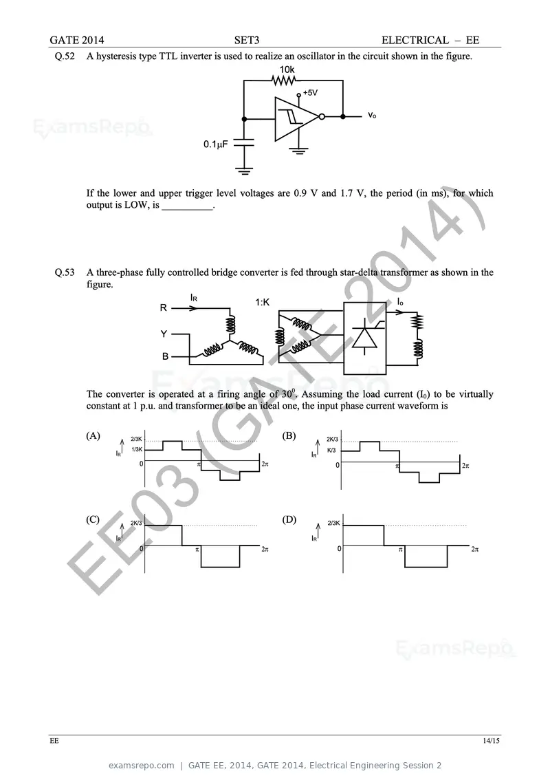
Text of page 63
GATE 2014                                       SET3                                   ELECTRICAL – EE
 Q.52   A hysteresis type TTL inverter is used to realize an oscillator in the circuit shown in the figure.
                                                            10k

                                                                  +5V

                                                                                  vo


                                        0.1µF


        If the lower and upper trigger level voltages are 0.9 V and 1.7 V, the period (in ms), for which
        output is LOW, is __________.


 Q.53
                                                                  2014
        A three-phase fully controlled bridge converter is fed through star-delta transformer as shown in the
        figure.

                           R

                           Y
                                  IR
                                                   1:K
                                                                      )                  Io


                           B                           E
                           (G
        The converter is operated at a firing angle of 300. Assuming the load current (I0) to be virtually


                             AT
        constant at 1 p.u. and transformer to be an ideal one, the input phase current waveform is

        (A)         2/3K                                    (B)         2K/3
                    1/3K                                                K/3
               IR                                                  IR
                       0            π                  2π                     0          π              2π


         03
        (C)
               IR
                    2K/3                                    (D)
                                                                   IR
                                                                        2/3K


EE                     0           π                   2π                     0          π                   2π


EE                                                                                                                14/15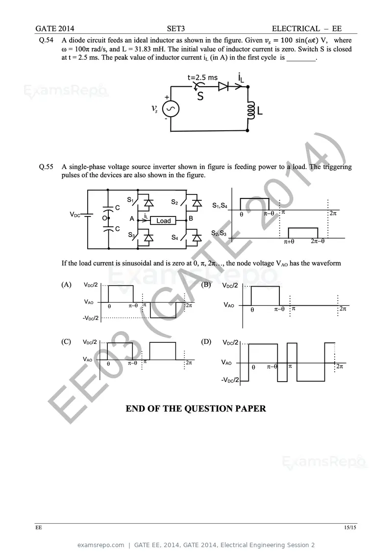
Text of page 64
GATE 2014                                         SET3                             ELECTRICAL – EE
 Q.54   A diode circuit feeds an ideal inductor as shown in the figure. Given vvss = 100 sin(ωtt) V, where
        ω = 100π rad/s, and L = 31.83 mH. The initial value of inductor current is zero. Switch S is closed
        at t = 2.5 ms. The peak value of inductor current iL (in A) in the first cycle is ________.


 Q.55
                                                                         20
        A single-phase voltage source inverter shown in figure is feeding power to a load. The triggering
        pulses of the devices are also shown in the figure.


                                                                           14
          VDC
                         O
                                 C


                                 C
                                     S1

                                     A

                                     S3
                                           iL
                                                Load
                                                       S2


                                                       S4
                                                            B
                                                                       S1,S4


                                                                       S2,S3
                                                                             )     θ       π−θ     π


                                                                                                   π+θ     2π−θ
                                                                                                                  2π


                                                            E
        If the load current is sinusoidal and is zero at 0, π, 2π…, the node voltage VAO has the waveform

        (A)     VDC/2
                             (G                                  (B)      VDC/2

                VAO

                -VDC/2
                             θ
                               AT    π−θ π                  2π             VAO
                                                                                       θ         π−θ   π               2π


        (C)     VDC/2                                            (D)      VDC/2


         03     VAO
                         θ           π−θ   π                2π            VAO

                                                                          -VDC/2
                                                                                       θ   π−θ         π           2π


EE                                   END OF THE QUESTION PAPER


EE                                                                                                                      15/15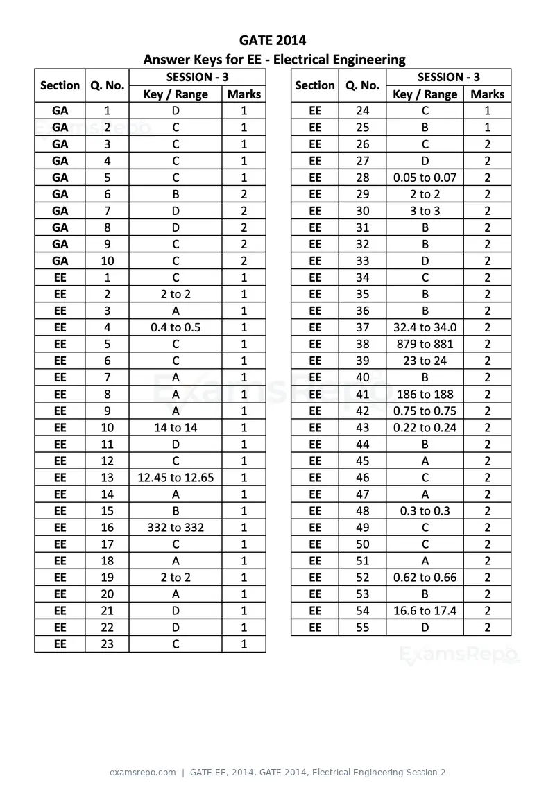
Text of page 65
GATE 2014
                 Answer Keys for EE ‐ Electrical Engineering
                       SESSION ‐ 3                            SESSION ‐ 3
Section Q. No.                           Section Q. No.
                  Key / Range Marks                       Key / Range Marks
 GA       1             D          1        EE     24           C         1
 GA       2             C          1        EE     25          B          1
 GA       3             C          1        EE     26           C         2
 GA       4             C          1        EE     27          D          2
 GA       5             C          1        EE     28     0.05 to 0.07    2
 GA       6             B          2        EE     29        2 to 2       2
 GA        7            D          2        EE     30        3 to 3       2
 GA        8            D          2        EE     31          B          2
 GA        9            C          2        EE     32          B          2
 GA       10            C          2        EE     33          D          2
 EE        1            C          1        EE     34           C         2
 EE        2          2 to 2       1        EE     35          B          2
 EE        3            A          1        EE     36          B          2
 EE        4        0.4 to 0.5     1        EE     37     32.4 to 34.0    2
 EE        5            C          1        EE     38      879 to 881     2
 EE        6            C          1        EE     39       23 to 24      2
 EE       7             A          1        EE     40          B          2
 EE       8             A          1        EE     41      186 to 188     2
 EE       9             A          1        EE     42     0.75 to 0.75    2
 EE       10        14 to 14       1        EE     43     0.22 to 0.24    2
 EE       11            D          1        EE     44          B          2
 EE       12            C          1        EE     45          A          2
 EE       13     12.45 to 12.65    1        EE     46           C         2
 EE       14            A          1        EE     47          A          2
 EE       15            B          1        EE     48      0.3 to 0.3     2
 EE       16       332 to 332      1        EE     49           C         2
 EE       17            C          1        EE     50           C         2
 EE       18            A          1        EE     51          A          2
 EE       19          2 to 2       1        EE     52     0.62 to 0.66    2
 EE       20            A          1        EE     53          B          2
 EE       21            D          1        EE     54     16.6 to 17.4    2
 EE       22            D          1        EE     55          D          2
 EE       23            C          1
Official key not published for this paper.
Page 1 of 65
Source: GATE. Question paper published by GATE.