
GATE EE 2023: Electrical Engineering
Text of page 1
Electrical Engineering (EE)


General Aptitude (GA)
Q.1 – Q.5 Carry ONE mark Each

 Q.1       Rafi told Mary, “I am thinking of watching a film this weekend.”

           The following reports the above statement in indirect speech:

           Rafi told Mary that he _______ of watching a film that weekend.


 (A)       thought


 (B)       is thinking


 (C)       am thinking


 (D)       was thinking


 Q.2       Permit : _______ : : Enforce : Relax

           (By word meaning)


 (A)       Allow


 (B)       Forbid


 (C)       License


 (D)       Reinforce


                                          Page 1 of 42
Organizing Institute: IIT Kanpur
Text of page 2
Electrical Engineering (EE)


 Q.3       Given a fair six-faced dice where the faces are labelled ‘1’, ‘2’, ‘3’, ‘4’, ‘5’, and ‘6’,
           what is the probability of getting a ‘1’ on the first roll of the dice and a ‘4’ on the
           second roll?


 (A)       1
           36


 (B)       1
           6


 (C)       5
           6


 (D)       1
           3


                                            Page 2 of 42
Organizing Institute: IIT Kanpur
Text of page 3
Electrical Engineering (EE)


 Q.4       A recent survey shows that 65% of tobacco users were advised to stop consuming
           tobacco. The survey also shows that 3 out of 10 tobacco users attempted to stop
           using tobacco.

           Based only on the information in the above passage, which one of the following
           options can be logically inferred with certainty?


 (A)       A majority of tobacco users who were advised to stop consuming tobacco made an
           attempt to do so.


 (B)       A majority of tobacco users who were advised to stop consuming tobacco did not
           attempt to do so.


 (C)       Approximately 30% of tobacco users successfully stopped consuming tobacco.


 (D)       Approximately 65% of tobacco users successfully stopped consuming tobacco.


                                        Page 3 of 42
Organizing Institute: IIT Kanpur
Text of page 4
Electrical Engineering (EE)


 Q.5       How many triangles are present in the given figure?


 (A)       12


 (B)       16


 (C)       20


 (D)       24


                                         Page 4 of 42
Organizing Institute: IIT Kanpur
Text of page 5
Electrical Engineering (EE)


Q.6 – Q.10 Carry TWO marks Each

 Q.6       Students of all the departments of a college who have successfully completed the
           registration process are eligible to vote in the upcoming college elections. However,
           by the time the due date for registration was over, it was found that suprisingly none
           of the students from the Department of Human Sciences had completed the
           registration process.

           Based only on the information provided above, which one of the following sets of
           statement(s) can be logically inferred with certainty?

            (i)       All those students who would not be eligible to vote in the college elections
                      would certainly belong to the Department of Human Sciences.
           (ii)       None of the students from departments other than Human Sciences failed to
                      complete the registration process within the due time.
           (iii)      All the eligible voters would certainly be students who are not from the
                      Department of Human Sciences.


 (A)       (i) and (ii)


 (B)       (i) and (iii)


 (C)       only (i)


 (D)       only (iii)


                                              Page 5 of 42
Organizing Institute: IIT Kanpur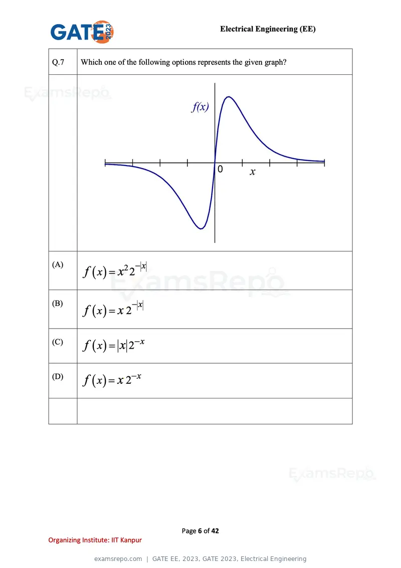
Text of page 6
Electrical Engineering (EE)


 Q.7       Which one of the following options represents the given graph?


                             −x
            f ( x ) = x2 2
 (A)


                             −x
            f ( x) = x 2
 (B)                     .


 (C)
            f ( x ) = x 2− x

 (D)
            f ( x ) = x. 2− x


                                         Page 6 of 42
Organizing Institute: IIT Kanpur
Text of page 7
Electrical Engineering (EE)


 Q.8       Which one of the options does NOT describe the passage below or follow from it?

                   We tend to think of cancer as a ‘modern’ illness because its metaphors are
                   so modern. It is a disease of overproduction, of sudden growth, a growth
                   that is unstoppable, tipped into the abyss of no control. Modern cell biology
                   encourages us to imagine the cell as a molecular machine. Cancer is that
                   machine unable to quench its intial command (to grow) and thus transform
                   into an indestructible, self-propelled automaton.

                       [Adapted from The Emperor of All Maladies by Siddhartha Mukherjee]


 (A)       It is a reflection of why cancer seems so modern to most of us.


 (B)       It tells us that modern cell biology uses and promotes metaphors of machinery.


 (C)       Modern cell biology encourages metaphors of machinery, and cancer is often
           imagined as a machine.


 (D)       Modern cell biology never uses figurative language, such as metaphors, to describe
           or explain anything.


                                           Page 7 of 42
Organizing Institute: IIT Kanpur
Text of page 8
Electrical Engineering (EE)
Q.9 The digit in the unit’s place of the product 3
999
71000 is _______.
(A) 7
(B) 1
(C) 3
(D) 9
Page 8 of 42
Organizing Institute: IIT Kanpur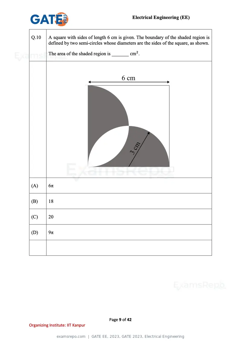
Text of page 9
Electrical Engineering (EE)


 Q.10      A square with sides of length 6 cm is given. The boundary of the shaded region is
           defined by two semi-circles whose diameters are the sides of the square, as shown.

           The area of the shaded region is _______ cm2 .


 (A)       6π


 (B)       18


 (C)       20


 (D)       9π


                                         Page 9 of 42
Organizing Institute: IIT Kanpur
Text of page 10
Electrical Engineering (EE)


Electrical Engineering
Q.11 – Q.35 Carry ONE mark Each

 Q.11 For a given vector w = [1 2 3]T, the vector normal to the plane defined by wTx = 1 is


 (A)     [−2 −2 2]T


 (B)     [3 0     −1]T


 (C)     [3 2     1]T


 (D)     [1 2     3]T


                                       Page 10 of 42
Organizing Institute: IIT Kanpur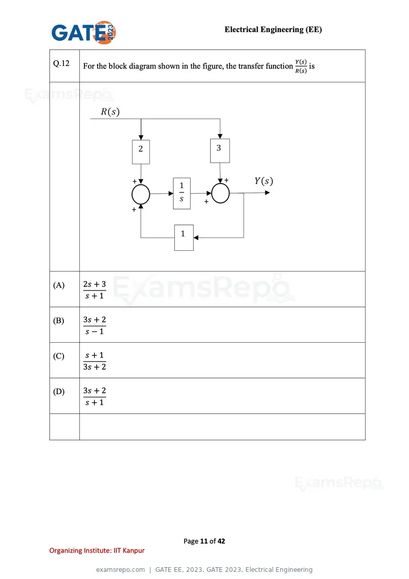
Text of page 11
Electrical Engineering (EE)


 Q.12                                                                       Y(s)
           For the block diagram shown in the figure, the transfer function R(s) is


 (A)       2s + 3
           s+1

 (B)       3s + 2
           s−1

 (C)       s+1
           3s + 2

 (D)       3s + 2
           s+1


                                          Page 11 of 42
Organizing Institute: IIT Kanpur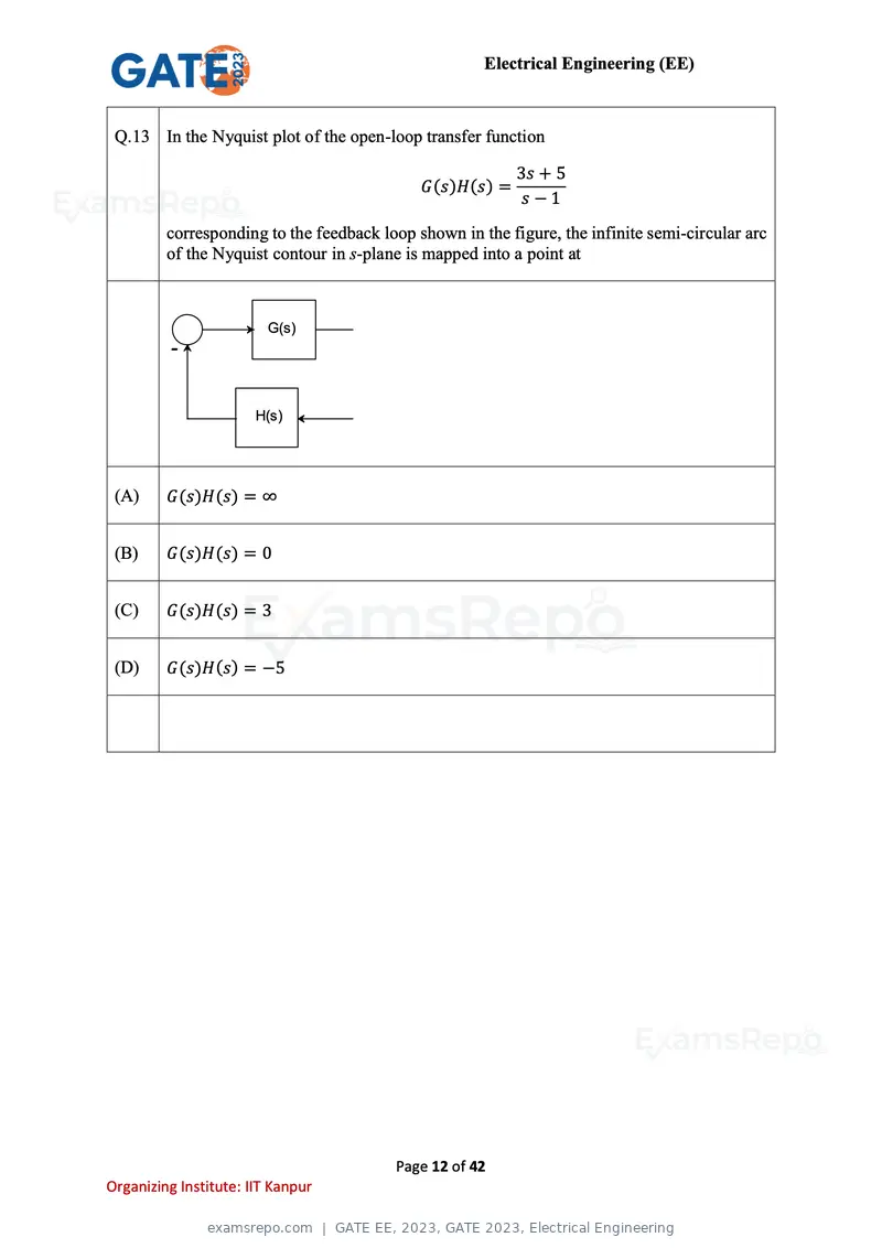
Text of page 12
Electrical Engineering (EE)


 Q.13 In the Nyquist plot of the open-loop transfer function

                                                           3s + 5
                                             G(s)H(s) =
                                                           s−1
         corresponding to the feedback loop shown in the figure, the infinite semi-circular arc
         of the Nyquist contour in s-plane is mapped into a point at


                         G(s)
          -


                       H(s)


 (A)     G(s)H(s) = ∞


 (B)     G(s)H(s) = 0


 (C)     G(s)H(s) = 3


 (D)     G(s)H(s) = −5


                                         Page 12 of 42
Organizing Institute: IIT Kanpur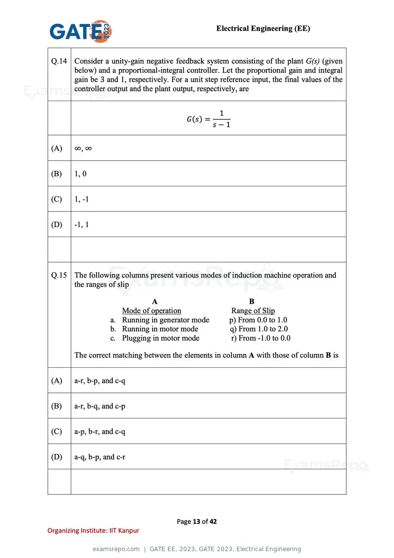
Text of page 13
Electrical Engineering (EE)


 Q.14 Consider a unity-gain negative feedback system consisting of the plant G(s) (given
      below) and a proportional-integral controller. Let the proportional gain and integral
      gain be 3 and 1, respectively. For a unit step reference input, the final values of the
      controller output and the plant output, respectively, are


                                                     1
                                           G(s) =
                                                    s−1

 (A)     ∞, ∞


 (B)     1, 0


 (C)     1, -1


 (D)     -1, 1


 Q.15 The following columns present various modes of induction machine operation and
      the ranges of slip

                                 A                              B
                        Mode of operation                 Range of Slip
                     a. Running in generator mode        p) From 0.0 to 1.0
                     b. Running in motor mode            q) From 1.0 to 2.0
                     c. Plugging in motor mode            r) From -1.0 to 0.0

         The correct matching between the elements in column A with those of column B is


 (A)     a-r, b-p, and c-q


 (B)     a-r, b-q, and c-p


 (C)     a-p, b-r, and c-q


 (D)     a-q, b-p, and c-r


                                        Page 13 of 42
Organizing Institute: IIT Kanpur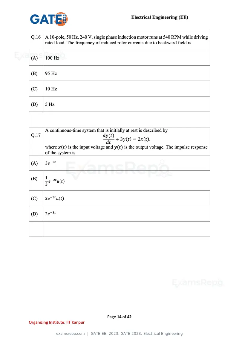
Text of page 14
Electrical Engineering (EE)


 Q.16 A 10-pole, 50 Hz, 240 V, single phase induction motor runs at 540 RPM while driving
      rated load. The frequency of induced rotor currents due to backward field is


 (A)     100 Hz


 (B)     95 Hz


 (C)     10 Hz


 (D)     5 Hz


         A continuous-time system that is initially at rest is described by
 Q.17                                  dy(t)
                                             + 3y(t) = 2x(t),
                                         dt
         where x(t) is the input voltage and y(t) is the output voltage. The impulse response
         of the system is

 (A)     3e −2t


 (B)     1 −2t
           e u(t)
         3


 (C)     2e −3t u(t)


 (D)     2e −3t


                                         Page 14 of 42
Organizing Institute: IIT Kanpur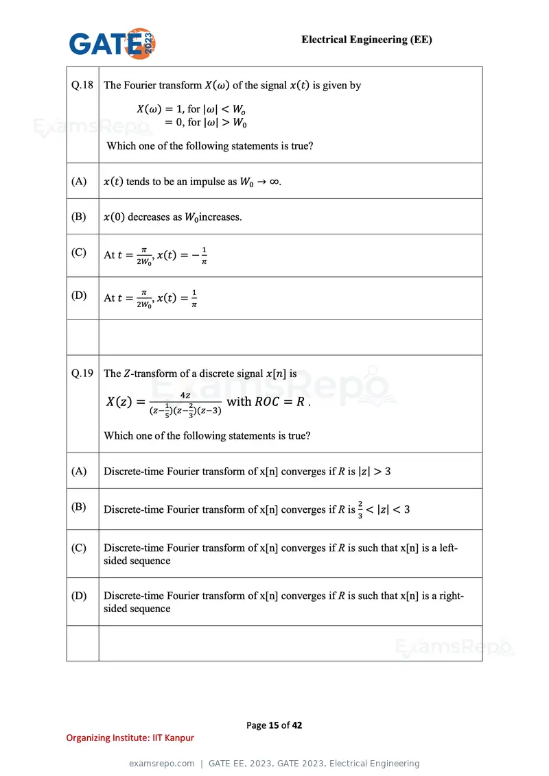
Text of page 15
Electrical Engineering (EE)


 Q.18 The Fourier transform X(ω) of the signal x(t) is given by

                 X(ω) = 1, for |ω| < Wo
                      = 0, for |ω| > W0

          Which one of the following statements is true?


 (A)     x(t) tends to be an impulse as W0 → ∞.


 (B)     x(0) decreases as W0 increases.


 (C)              π                  1
         At t = 2W , x(t) = − π
                      0


 (D)              π              1
         At t = 2W , x(t) = π
                      0


 Q.19 The Z-transform of a discrete signal x[n] is
                            4z
          X(z) =         1    2          with ROC = R .
                      (z− )(z− )(z−3)
                         5    3

         Which one of the following statements is true?


 (A)     Discrete-time Fourier transform of x[n] converges if R is |z| > 3


 (B)                                                                2
         Discrete-time Fourier transform of x[n] converges if R is 3 < |z| < 3


 (C)     Discrete-time Fourier transform of x[n] converges if R is such that x[n] is a left-
         sided sequence


 (D)     Discrete-time Fourier transform of x[n] converges if R is such that x[n] is a right-
         sided sequence


                                            Page 15 of 42
Organizing Institute: IIT Kanpur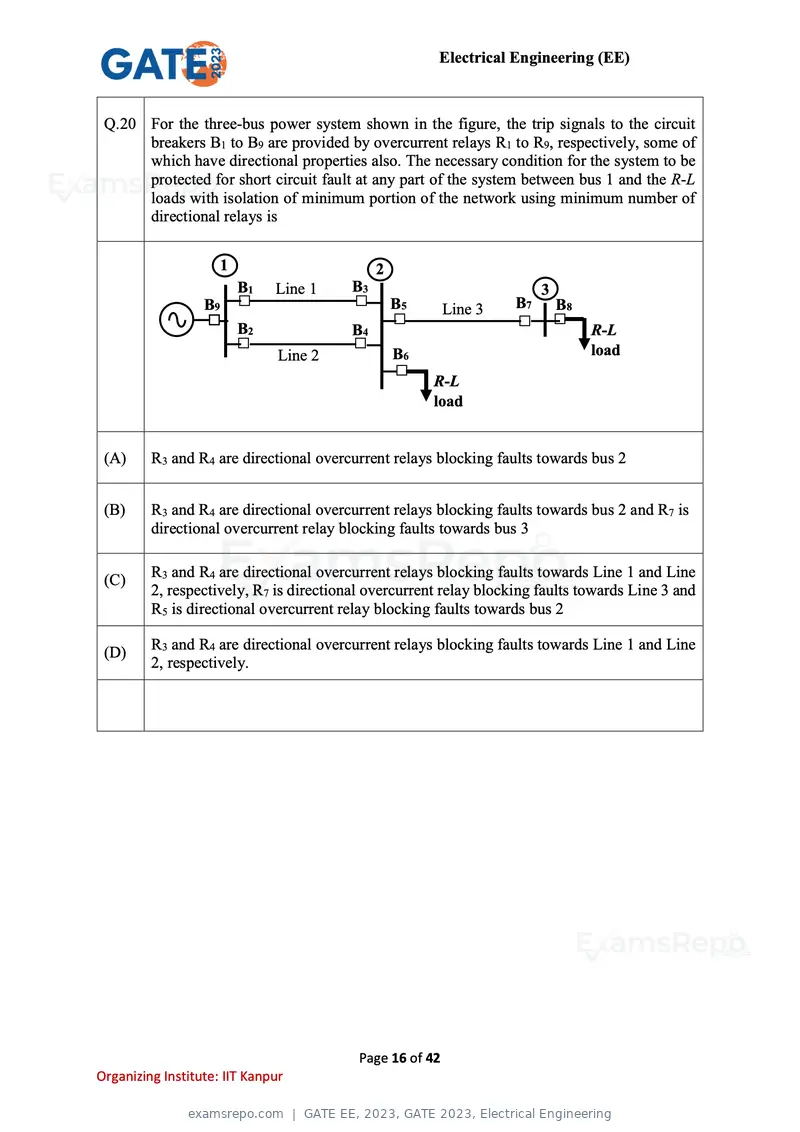
Text of page 16
Electrical Engineering (EE)


 Q.20 For the three-bus power system shown in the figure, the trip signals to the circuit
      breakers B1 to B9 are provided by overcurrent relays R1 to R9, respectively, some of
      which have directional properties also. The necessary condition for the system to be
      protected for short circuit fault at any part of the system between bus 1 and the R-L
      loads with isolation of minimum portion of the network using minimum number of
      directional relays is


                     1                        2
                         B1   Line 1     B3                           3
                  B9                              B5      Line 3   B7 3 B8
                         B2              B4                                    R-L
                               Line 2             B6                           load
                                                       R-L
                                                       load


 (A)     R3 and R4 are directional overcurrent relays blocking faults towards bus 2


 (B)     R3 and R4 are directional overcurrent relays blocking faults towards bus 2 and R7 is
         directional overcurrent relay blocking faults towards bus 3

         R3 and R4 are directional overcurrent relays blocking faults towards Line 1 and Line
 (C)
         2, respectively, R7 is directional overcurrent relay blocking faults towards Line 3 and
         R5 is directional overcurrent relay blocking faults towards bus 2

         R3 and R4 are directional overcurrent relays blocking faults towards Line 1 and Line
 (D)
         2, respectively.


                                          Page 16 of 42
Organizing Institute: IIT Kanpur
Text of page 17
Electrical Engineering (EE)


      The expressions of fuel cost of two thermal generating units as a function of the
 Q.21 respective power generation PG1 and PG2 are given as
                         2
       F1 (PG1 ) = 0.1aPG1 + 40 PG1 + 120 Rs/ℎour          0 MW ≤ PG1 ≤ 350 MW
                       2
      F2 (PG2 ) = 0.2PG2 + 30 PG2 + 100 Rs/ℎour            0 MW ≤ PG2 ≤ 300 MW

         where a is a constant. For a given value of a, optimal dispatch requires the total load
         of 290 MW to be shared as PG1 = 175 MW and PG2 = 115 MW. With the load
         remaining unchanged, the value of a is increased by 10% and optimal dispatch is
         carried out. The changes in PG1 and the total cost of generation, F (= F1 + F2) in
         Rs/hour will be as follows


 (A)     PG1 will decrease and F will increase


 (B)     Both PG1 and F will increase


 (C)     PG1 will increase and F will decrease


 (D)     Both PG1 and F will decrease


                                          Page 17 of 42
Organizing Institute: IIT Kanpur
Text of page 18
Electrical Engineering (EE)
Q.22 The four stator conductors (A, A, B and B) of a rotating machine are carrying DC
currents of the same value, the directions of which are shown in the figure (i). The
rotor coils a-a and b-b are formed by connecting the back ends of conductors ‘a’
and ‘a’ and ‘b’ and ‘b’, respectively, as shown in figure (ii). The e.m.f. induced in
coil a-a and coil b-b are denoted by Ea-a and Eb-b, respectively. If the rotor is
rotated at uniform angular speed rad/s in the clockwise direction then which of the
following correctly describes the Ea-a and Eb-b ?
figure (i): cross-sectional view figure (ii): rotor winding connection diagram
(A) Ea-a and Eb-b have finite magnitudes and are in the same phase
(B) Ea-a and Eb-b have finite magnitudes with Eb-b leading Ea-a
(C) Ea-a and Eb-b have finite magnitudes with Ea-a leading Eb-b
(D) Ea-a = Eb-b = 0
Page 18 of 42
Organizing Institute: IIT Kanpur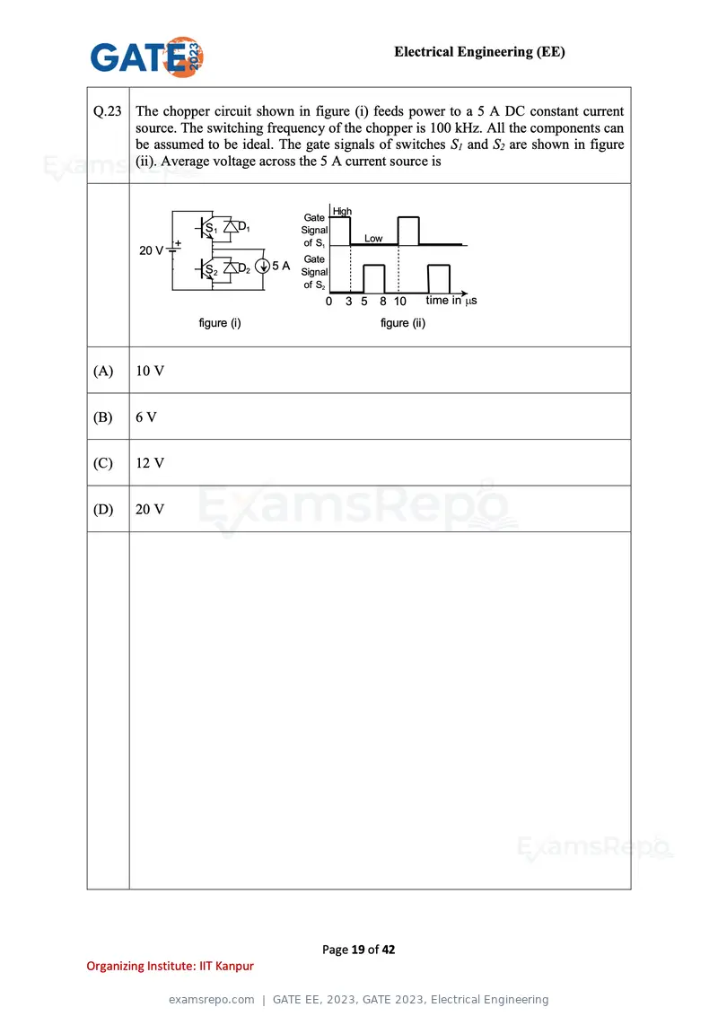
Text of page 19
Electrical Engineering (EE)


 Q.23 The chopper circuit shown in figure (i) feeds power to a 5 A DC constant current
      source. The switching frequency of the chopper is 100 kHz. All the components can
      be assumed to be ideal. The gate signals of switches S1 and S2 are shown in figure
      (ii). Average voltage across the 5 A current source is


                                                    High
                                        Gate
                      S1      D1        Signal
                                                           Low
                 +                      of S1
          20 V
                                        Gate
                      S2      D2   5 A Signal
                                        of S2
                                                0     3 5    8 10          time in s
                     figure (i)                              figure (ii)


 (A)     10 V


 (B)     6V


 (C)     12 V


 (D)     20 V


                                            Page 19 of 42
Organizing Institute: IIT Kanpur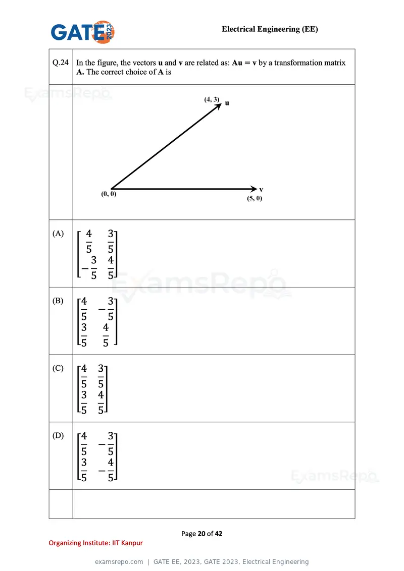
Text of page 20
Electrical Engineering (EE)


 Q.24 In the figure, the vectors u and v are related as: Au = v by a transformation matrix
      A. The correct choice of A is


 (A)       4        3
         [ 5        5]
            3       4
          −
            5       5

 (B)      4        3
                −
         [5        5]
          3       4
          5       5

 (C)      4     3
         [5     5]
          3     4
          5     5

 (D)      4       3
                −
         [5       5]
          3       4
                −
          5       5


                                        Page 20 of 42
Organizing Institute: IIT Kanpur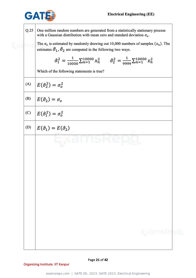
Text of page 21
Electrical Engineering (EE)


 Q.25 One million random numbers are generated from a statistically stationary process
      with a Gaussian distribution with mean zero and standard deviation σo .

         The σo is estimated by randomly drawing out 10,000 numbers of samples (xn ). The
         estimates σ̂1 , σ̂2 are computed in the following two ways.
                                   1                                1
                     σ̂12 =            ∑10000
                                        n=1 xn
                                              2
                                                          σ̂22 =          ∑10000
                                                                           n=1 xn
                                                                                 2
                              10000                                9999

         Which of the following statements is true?


 (A)     E (σ̂22 ) = σo2

 (B)     E (σ̂2 ) = σo

 (C)     E (σ̂12 ) = σo2

 (D)     E (σ̂1 ) = E (σ̂2 )


                                          Page 21 of 42
Organizing Institute: IIT Kanpur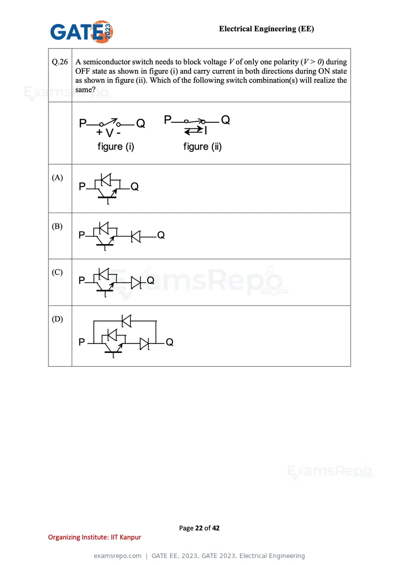
Text of page 22
Electrical Engineering (EE)


 Q.26 A semiconductor switch needs to block voltage V of only one polarity (V > 0) during
      OFF state as shown in figure (i) and carry current in both directions during ON state
      as shown in figure (ii). Which of the following switch combination(s) will realize the
      same?


          P                   Q        P                       Q
                +V-                                   I
                 figure (i)                     figure (ii)


 (A)
          P                 Q


 (B)
          P                            Q


 (C)
          P                        Q


 (D)

          P                                Q


                                               Page 22 of 42
Organizing Institute: IIT Kanpur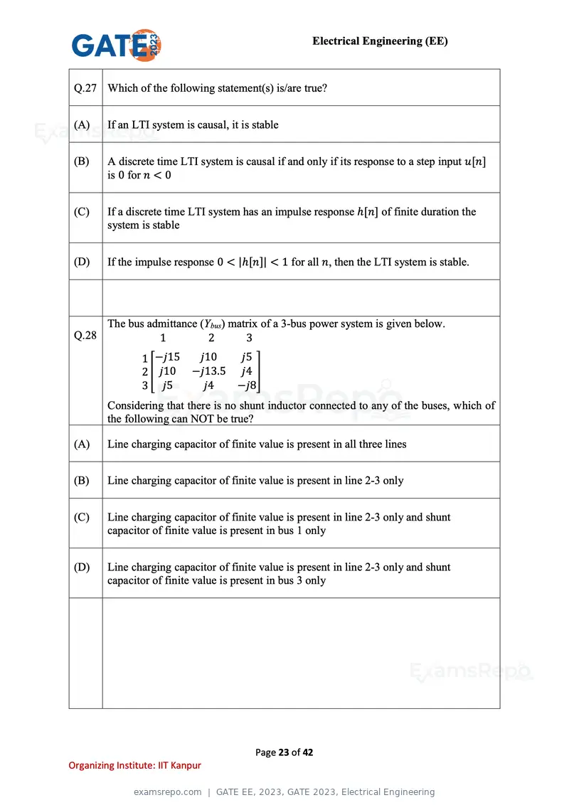
Text of page 23
Electrical Engineering (EE)


 Q.27 Which of the following statement(s) is/are true?


 (A)     If an LTI system is causal, it is stable


 (B)     A discrete time LTI system is causal if and only if its response to a step input u[n]
         is 0 for n < 0


 (C)     If a discrete time LTI system has an impulse response ℎ[n] of finite duration the
         system is stable


 (D)     If the impulse response 0 < |ℎ[n]| < 1 for all n, then the LTI system is stable.


         The bus admittance (Ybus) matrix of a 3-bus power system is given below.
 Q.28              1          2       3
                 1 −j15  j10   j5
                 2[ j10 −j13.5 j4 ]
                 3 j5     j4   −j8
         Considering that there is no shunt inductor connected to any of the buses, which of
         the following can NOT be true?

 (A)     Line charging capacitor of finite value is present in all three lines


 (B)     Line charging capacitor of finite value is present in line 2-3 only


 (C)     Line charging capacitor of finite value is present in line 2-3 only and shunt
         capacitor of finite value is present in bus 1 only


 (D)     Line charging capacitor of finite value is present in line 2-3 only and shunt
         capacitor of finite value is present in bus 3 only


                                           Page 23 of 42
Organizing Institute: IIT Kanpur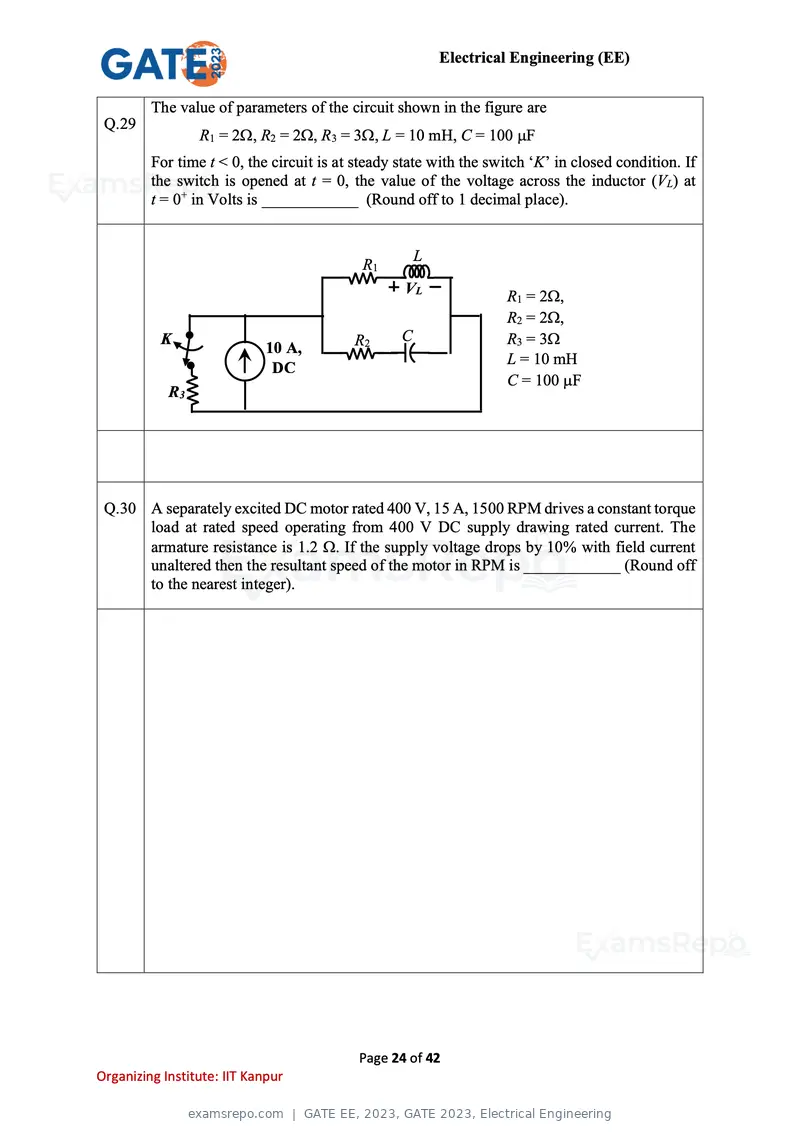
Text of page 24
Electrical Engineering (EE)
The value of parameters of the circuit shown in the figure are
Q.29
R1 = 2, R2 = 2, R3 = 3, L = 10 mH, C = 100 F
For time t < 0, the circuit is at steady state with the switch ‘K’ in closed condition. If
the switch is opened at t = 0, the value of the voltage across the inductor (VL) at
t = 0+ in Volts is ____________ (Round off to 1 decimal place).
L
R1
VL
R1 = 2,
R2 = 2,
K R2 C R3 = 3
10 A,
L = 10 mH
DC
C = 100 F
R3
Q.30 A separately excited DC motor rated 400 V, 15 A, 1500 RPM drives a constant torque
load at rated speed operating from 400 V DC supply drawing rated current. The
armature resistance is 1.2 . If the supply voltage drops by 10% with field current
unaltered then the resultant speed of the motor in RPM is ____________ (Round off
to the nearest integer).
Page 24 of 42
Organizing Institute: IIT Kanpur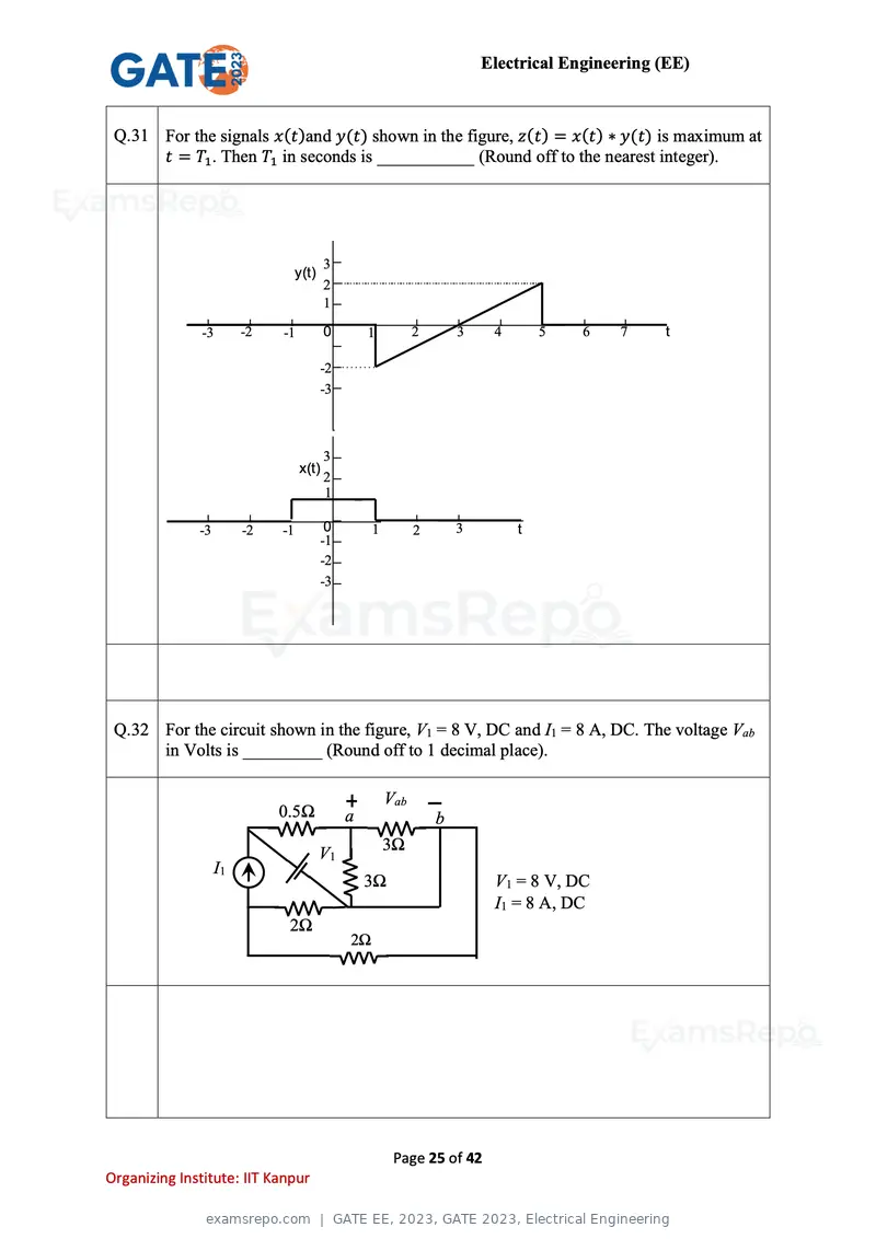
Text of page 25
Electrical Engineering (EE)


 Q.31 For the signals x(t)and y(t) shown in the figure, z(t) = x(t) ∗ y(t) is maximum at
      t = T1 . Then T1 in seconds is ___________ (Round off to the nearest integer).


                                          3
                                   y(t)
                                          2
                                          1

               -3        -2   -1          0        1          2       3    4       5   6    7    t

                                          -2
                                          -3


                                          3
                                   x(t)
                                          2
                                          1

              -3         -2   -1           0        1         2       3        t
                                          -1
                                          -2
                                          -3


 Q.32 For the circuit shown in the figure, V1 = 8 V, DC and I1 = 8 A, DC. The voltage Vab
      in Volts is _________ (Round off to 1 decimal place).

                                                        Vab
                              0.5Ω             a                  b
                                                        3Ω
                                          V1
                    I1
                                                   3Ω                      V1 = 8 V, DC
                                                                           I1 = 8 A, DC
                               2Ω
                                               2Ω


                                                         Page 25 of 42
Organizing Institute: IIT Kanpur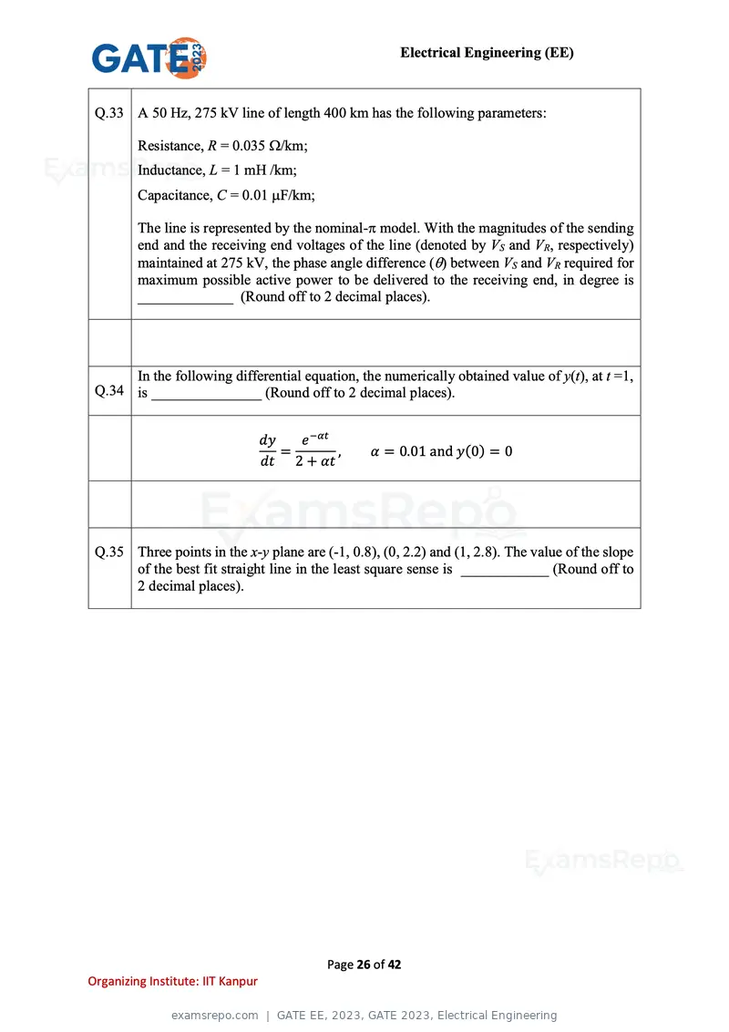
Text of page 26
Electrical Engineering (EE)
Q.33 A 50 Hz, 275 kV line of length 400 km has the following parameters:
Resistance, R = 0.035 /km;
Inductance, L = 1 mH /km;
Capacitance, C = 0.01 F/km;
The line is represented by the nominal- model. With the magnitudes of the sending
end and the receiving end voltages of the line (denoted by VS and VR, respectively)
maintained at 275 kV, the phase angle difference () between VS and VR required for
maximum possible active power to be delivered to the receiving end, in degree is
_____________ (Round off to 2 decimal places).
In the following differential equation, the numerically obtained value of y(t), at t =1,
Q.34 is _______________ (Round off to 2 decimal places).
dy e −αt
= , α = 0.01 and y(0) = 0
dt 2 + αt
Q.35 Three points in the x-y plane are (-1, 0.8), (0, 2.2) and (1, 2.8). The value of the slope
of the best fit straight line in the least square sense is ____________ (Round off to
2 decimal places).
Page 26 of 42
Organizing Institute: IIT Kanpur
Text of page 27
Electrical Engineering (EE)


Q.36 – Q.65 Carry TWO marks Each
           The magnitude and phase plots of an LTI system are shown in the figure. The
Q.36       transfer function of the system is


(A)        2.51e −0.032s


(B)        e −2.514s
            s+1


(C)        1.04e −2.514s


(D)        2.51e −1.047s


                                      Page 27 of 42
Organizing Institute: IIT Kanpur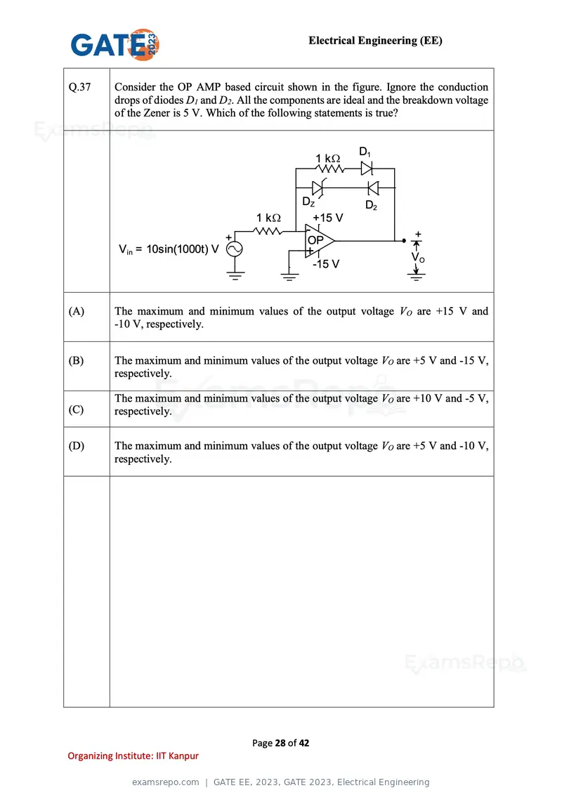
Text of page 28
Electrical Engineering (EE)


Q.37       Consider the OP AMP based circuit shown in the figure. Ignore the conduction
           drops of diodes D1 and D2. All the components are ideal and the breakdown voltage
           of the Zener is 5 V. Which of the following statements is true?


                                                                D1
                                                        1k


                                                   DZ            D2
                                         1k          +15 V
                                                    -                       +
                                   +                OP
            Vin = 10sin(1000t) V                    +                      VO
                                                        -15 V


(A)        The maximum and minimum values of the output voltage VO are +15 V and
           -10 V, respectively.


(B)        The maximum and minimum values of the output voltage VO are +5 V and -15 V,
           respectively.

           The maximum and minimum values of the output voltage VO are +10 V and -5 V,
(C)        respectively.


(D)        The maximum and minimum values of the output voltage VO are +5 V and -10 V,
           respectively.


                                        Page 28 of 42
Organizing Institute: IIT Kanpur
Text of page 29
Electrical Engineering (EE)


           Consider a lead compensator of the form
Q.38                                                 s
                                                 1+a
                                        K(s) =       s , β > 1, a > 0
                                                1+
                                                    βa
           The frequency at which this compensator produces maximum phase lead is 4 rad/s.
           At this frequency, the gain amplification provided by the controller, assuming
           asymptotic Bode-magnitude plot of K(s), is 6 dB. The values of a, β, respectively,
           are

(A)        1, 16


(B)        2, 4


(C)        3, 5


(D)        2.66, 2.25


                                         Page 29 of 42
Organizing Institute: IIT Kanpur
Text of page 30
Electrical Engineering (EE)


Q.39       A 3-phase, star-connected, balanced load is supplied from a 3-phase, 400 V (rms),
           balanced voltage source with phase sequence R-Y-B, as shown in the figure. If the
           wattmeter reading is −400 W and the line current is IR = 2 A (rms), then the power
           factor of the load per phase is


                                    Wattmeter

                          R    IR   M           L

                                    C               V    3 Phase
              3 Phase                   +   -              Star
               400 V      Y
                                                        Connected
             Balanced
                                                        Balanced
              Source
                         B                                 Load


(A)        Unity


(B)        0.5 leading


(C)        0.866 leading


(D)        0.707 lagging


                                            Page 30 of 42
Organizing Institute: IIT Kanpur
Text of page 31
Electrical Engineering (EE)


Q.40       An 8 bit ADC converts analog voltage in the range of 0 to +5 V to the corresponding
           digital code as per the conversion characteristics shown in figure.
           For Vin = 1.9922 V, which of the following digital output, given in hex, is true ?


            Digital
            Output in
            Hex


               03H

               02H


               01H

               00H
                                                           Vin in mV
                     0 9.8 19.6    39.2   58.8
                                                     Analog Input


(A)        64H


(B)        65H


(C)        66H


(D)        67H


                                                 Page 31 of 42
Organizing Institute: IIT Kanpur
Text of page 32
Electrical Engineering (EE)
Q.41 The three-bus power system shown in the figure has one alternator connected to
bus 2 which supplies 200 MW and 40 MVAr power. Bus 3 is infinite bus having a
voltage of magnitude |V3| =1.0 p.u. and angle of -15. A variable current source,
|I| is connected at bus 1 and controlled such that the magnitude of the bus 1
voltage is maintained at 1.05 p.u. and the phase angle of the source current,
π
= 12 , where 1 is the phase angle of the bus 1 voltage. The three buses can be
categorized for load flow analysis as
(A) Bus 1 Slack bus
Bus 2 P − |V| bus
Bus 3 P − Q bus
(B) Bus 1 P − |V| bus
Bus 2 P − |V| bus
Bus 3 Slack bus
(C) Bus 1 P − Q bus
Bus 2 P − Q bus
Bus 3 Slack bus
(D) Bus 1 P − |V| bus
Bus 2 P − Q bus
Bus 3 Slack bus
Page 32 of 42
Organizing Institute: IIT Kanpur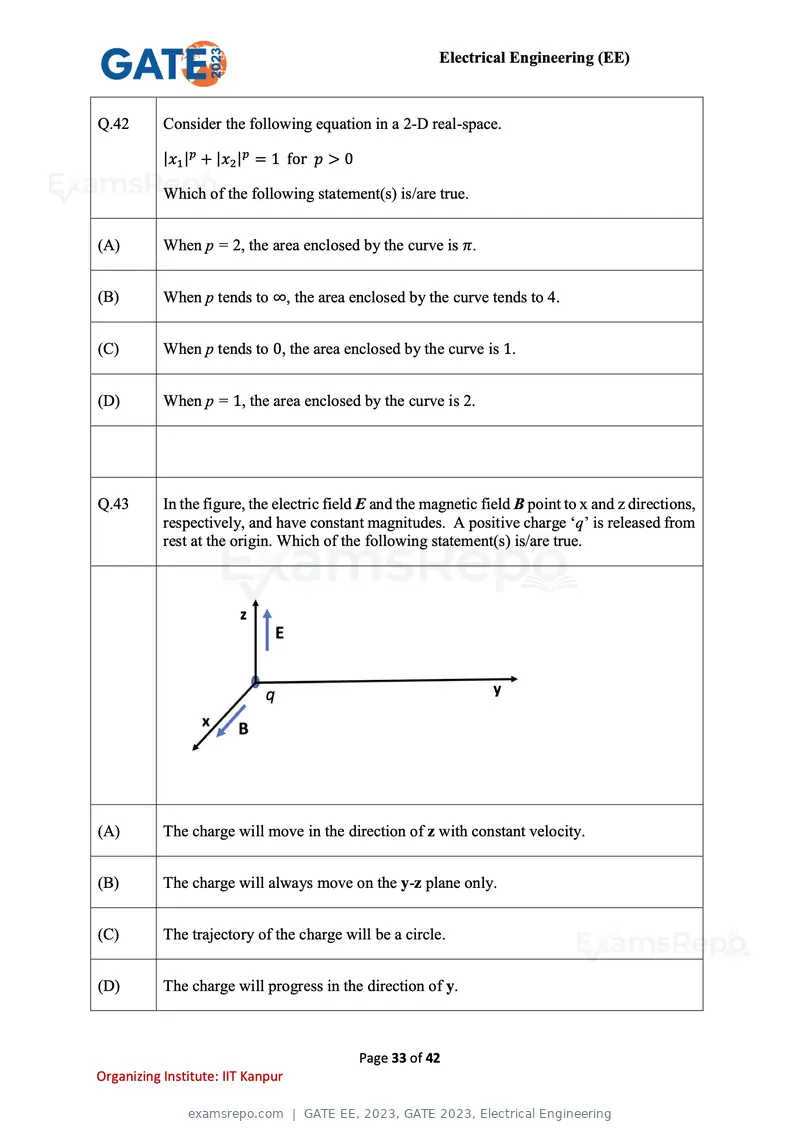
Text of page 33
Electrical Engineering (EE)


Q.42       Consider the following equation in a 2-D real-space.

           |x1 |p + |x2 |p = 1 for p > 0

           Which of the following statement(s) is/are true.


(A)        When p = 2, the area enclosed by the curve is π.


(B)        When p tends to ∞, the area enclosed by the curve tends to 4.


(C)        When p tends to 0, the area enclosed by the curve is 1.


(D)        When p = 1, the area enclosed by the curve is 2.


Q.43       In the figure, the electric field E and the magnetic field B point to x and z directions,
           respectively, and have constant magnitudes. A positive charge ‘q’ is released from
           rest at the origin. Which of the following statement(s) is/are true.


(A)        The charge will move in the direction of z with constant velocity.


(B)        The charge will always move on the y-z plane only.


(C)        The trajectory of the charge will be a circle.


(D)        The charge will progress in the direction of y.


                                           Page 33 of 42
Organizing Institute: IIT Kanpur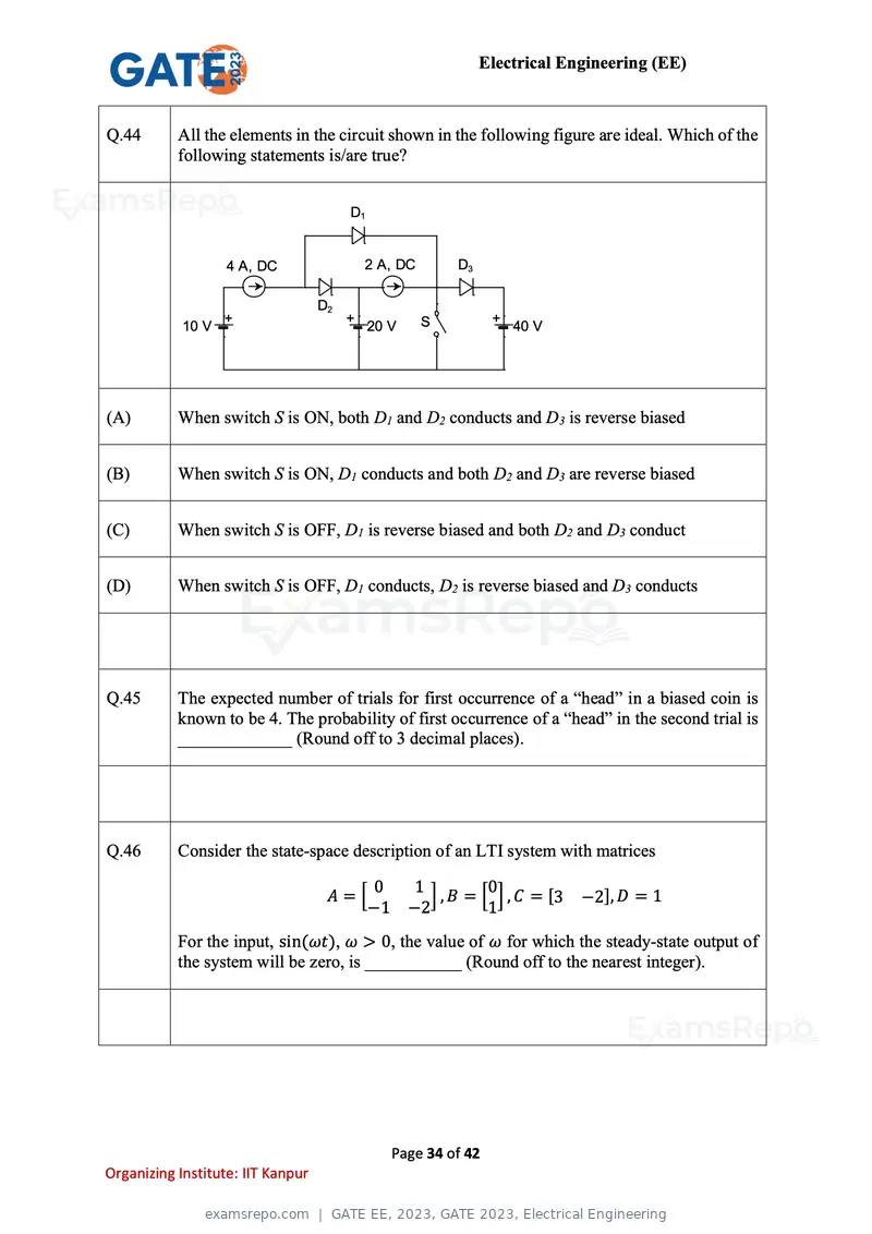
Text of page 34
Electrical Engineering (EE)


Q.44       All the elements in the circuit shown in the following figure are ideal. Which of the
           following statements is/are true?


                                        D1


                   4 A, DC                  2 A, DC        D3

                                   D2
                   +                    +             S          +
            10 V                             20 V                    40 V


(A)        When switch S is ON, both D1 and D2 conducts and D3 is reverse biased


(B)        When switch S is ON, D1 conducts and both D2 and D3 are reverse biased


(C)        When switch S is OFF, D1 is reverse biased and both D2 and D3 conduct


(D)        When switch S is OFF, D1 conducts, D2 is reverse biased and D3 conducts


Q.45       The expected number of trials for first occurrence of a “head” in a biased coin is
           known to be 4. The probability of first occurrence of a “head” in the second trial is
           _____________ (Round off to 3 decimal places).


Q.46       Consider the state-space description of an LTI system with matrices

                                        0           1          0
                                    A=[               ] , B = [ ] , C = [3   −2], D = 1
                                       −1           −2         1
           For the input, sin(ωt), ω > 0, the value of ω for which the steady-state output of
           the system will be zero, is ___________ (Round off to the nearest integer).


                                                Page 34 of 42
Organizing Institute: IIT Kanpur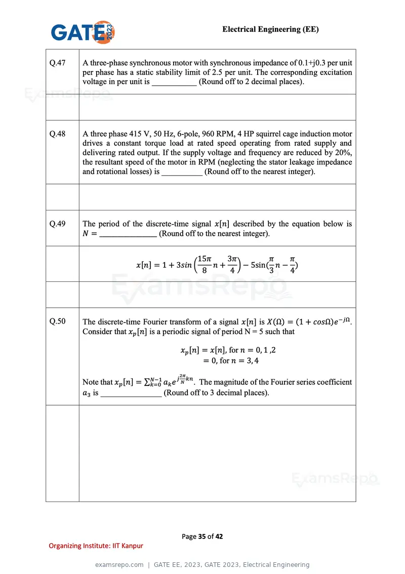
Text of page 35
Electrical Engineering (EE)


Q.47       A three-phase synchronous motor with synchronous impedance of 0.1+j0.3 per unit
           per phase has a static stability limit of 2.5 per unit. The corresponding excitation
           voltage in per unit is ___________ (Round off to 2 decimal places).


Q.48       A three phase 415 V, 50 Hz, 6-pole, 960 RPM, 4 HP squirrel cage induction motor
           drives a constant torque load at rated speed operating from rated supply and
           delivering rated output. If the supply voltage and frequency are reduced by 20%,
           the resultant speed of the motor in RPM (neglecting the stator leakage impedance
           and rotational losses) is __________ (Round off to the nearest integer).


Q.49       The period of the discrete-time signal x[n] described by the equation below is
           N = ___________________ (Round off to the nearest integer).


                                                 15π    3π        π   π
                             x[n] = 1 + 3sin (       n + ) − 5sin( n − )
                                                  8      4        3   4


Q.50       The discrete-time Fourier transform of a signal x[n] is X(Ω) = (1 + cosΩ)e −jΩ .
           Consider that xp [n] is a periodic signal of period N = 5 such that

                                         xp [n] = x[n], for n = 0, 1 ,2
                                                = 0, for n = 3, 4
                                         2π
                                       j kn
           Note that xp [n] = ∑N−1
                               k=0 ak e N   . The magnitude of the Fourier series coefficient
           a3 is _______________ (Round off to 3 decimal places).


                                         Page 35 of 42
Organizing Institute: IIT Kanpur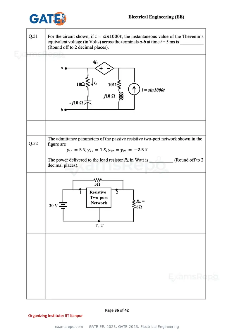
Text of page 36
Electrical Engineering (EE)
Q.51 For the circuit shown, if i = sin1000t, the instantaneous value of the Thevenin’s
equivalent voltage (in Volts) across the terminals a-b at time t = 5 ms is __________
(Round off to 2 decimal places).
4ix
a
10Ω ix 10
i = sin1000t
j10
10 mH
j10F
-100
b
The admittance parameters of the passive resistive two-port network shown in the
Q.52 figure are
y11 = 5 S, y22 = 1 S, y12 = y21 = −2.5 S
The power delivered to the load resistor RL in Watt is __________ (Round off to 2
decimal places).
Page 36 of 42
Organizing Institute: IIT Kanpur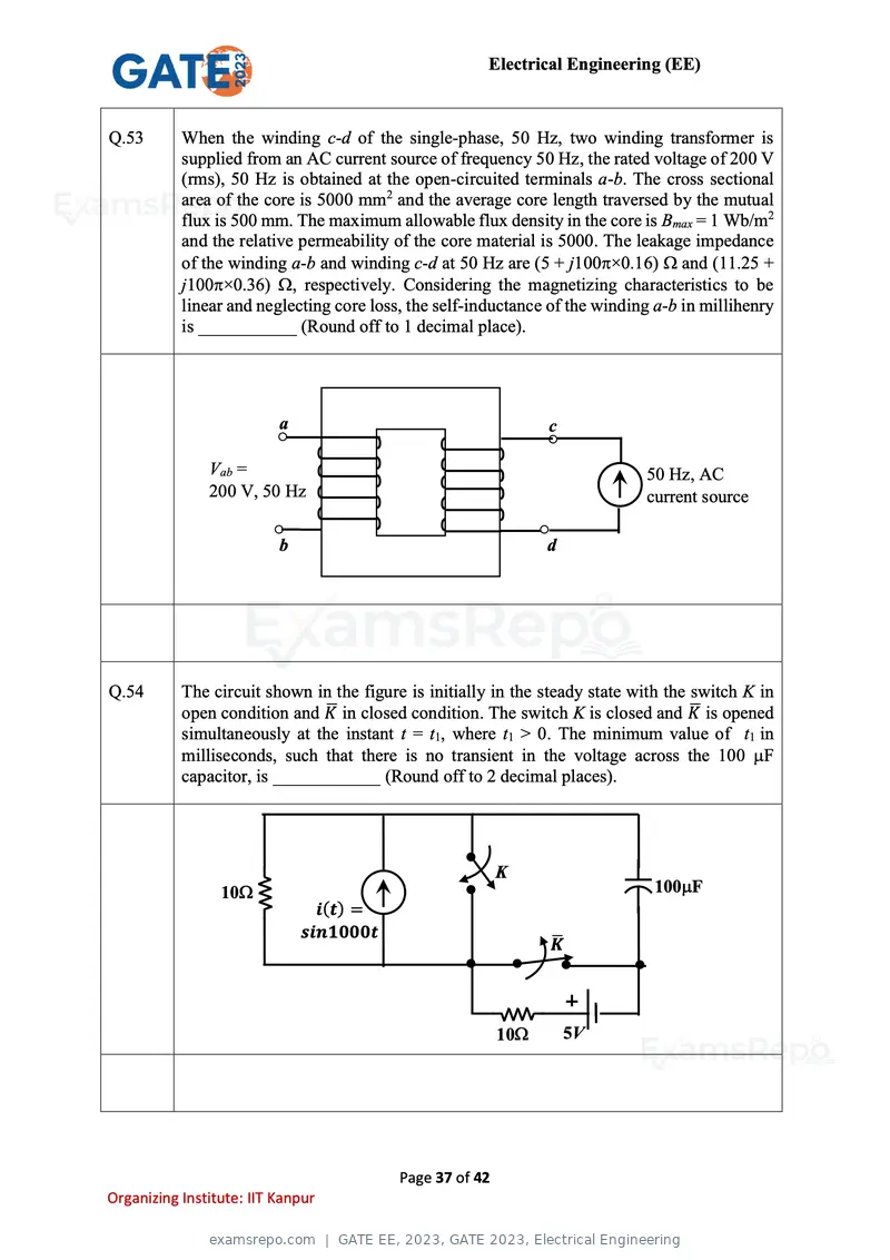
Text of page 37
Electrical Engineering (EE)
Q.53 When the winding c-d of the single-phase, 50 Hz, two winding transformer is
supplied from an AC current source of frequency 50 Hz, the rated voltage of 200 V
(rms), 50 Hz is obtained at the open-circuited terminals a-b. The cross sectional
area of the core is 5000 mm2 and the average core length traversed by the mutual
flux is 500 mm. The maximum allowable flux density in the core is Bmax = 1 Wb/m2
and the relative permeability of the core material is 5000. The leakage impedance
of the winding a-b and winding c-d at 50 Hz are (5 + j100×0.16) and (11.25 +
j100×0.36) , respectively. Considering the magnetizing characteristics to be
linear and neglecting core loss, the self-inductance of the winding a-b in millihenry
is ___________ (Round off to 1 decimal place).
a c
Vab = 50 Hz, AC
200 V, 50 Hz current source
b d
Q.54 The circuit shown in the figure is initially in the steady state with the switch K in
open condition and K̅ in closed condition. The switch K is closed and K ̅ is opened
simultaneously at the instant t = t1, where t1 > 0. The minimum value of t1 in
milliseconds, such that there is no transient in the voltage across the 100 F
capacitor, is ____________ (Round off to 2 decimal places).
K
10 100F
i(t) =
sin1000t
̅
K
10 5V
Page 37 of 42
Organizing Institute: IIT Kanpur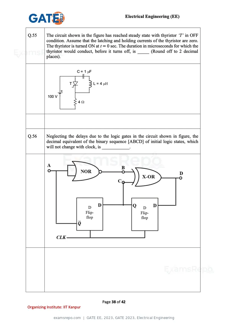
Text of page 38
Electrical Engineering (EE)


Q.55       The circuit shown in the figure has reached steady state with thyristor ‘T’ in OFF
           condition. Assume that the latching and holding currents of the thyristor are zero.
           The thyristor is turned ON at t = 0 sec. The duration in microseconds for which the
           thyristor would conduct, before it turns off, is _____ (Round off to 2 decimal
           places).


                             C=1 F


                         T           L=4

                    +
            100 V
                              4


Q.56       Neglecting the delays due to the logic gates in the circuit shown in figure, the
           decimal equivalent of the binary sequence [ABCD] of initial logic states, which
           will not change with clock, is ____________.


                                           Page 38 of 42
Organizing Institute: IIT Kanpur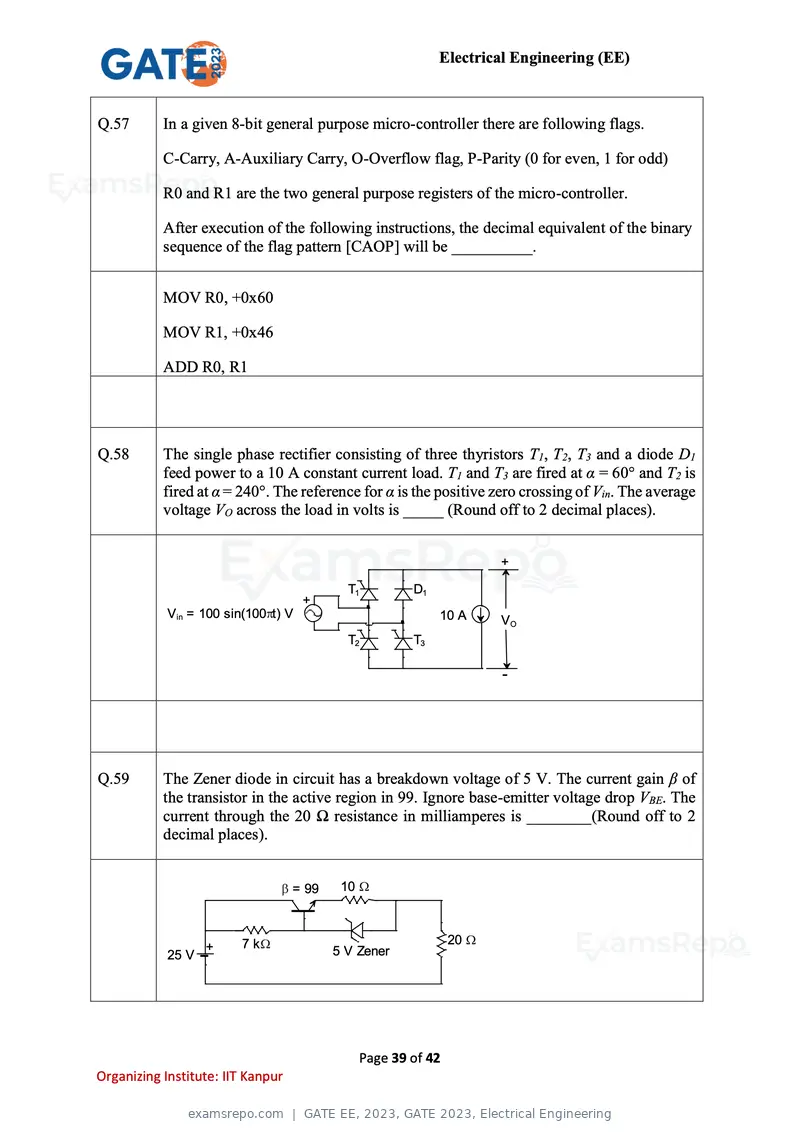
Text of page 39
Electrical Engineering (EE)


Q.57       In a given 8-bit general purpose micro-controller there are following flags.

           C-Carry, A-Auxiliary Carry, O-Overflow flag, P-Parity (0 for even, 1 for odd)

           R0 and R1 are the two general purpose registers of the micro-controller.

           After execution of the following instructions, the decimal equivalent of the binary
           sequence of the flag pattern [CAOP] will be __________.


           MOV R0, +0x60

           MOV R1, +0x46

           ADD R0, R1


Q.58       The single phase rectifier consisting of three thyristors T1, T2, T3 and a diode D1
           feed power to a 10 A constant current load. T1 and T3 are fired at α = 60° and T2 is
           fired at α = 240°. The reference for α is the positive zero crossing of Vin. The average
           voltage VO across the load in volts is _____ (Round off to 2 decimal places).


                                                                     +

                                            T1          D1
                                     +
            Vin = 100 sin(100 t) V                           10 A    VO
                                            T2          T3

                                                                     -


Q.59       The Zener diode in circuit has a breakdown voltage of 5 V. The current gain β of
           the transistor in the active region in 99. Ignore base-emitter voltage drop VBE. The
           current through the 20 Ω resistance in milliamperes is ________(Round off to 2
           decimal places).


                                   = 99    10


                         7k                                     20
                   +                      5 V Zener
            25 V


                                                Page 39 of 42
Organizing Institute: IIT Kanpur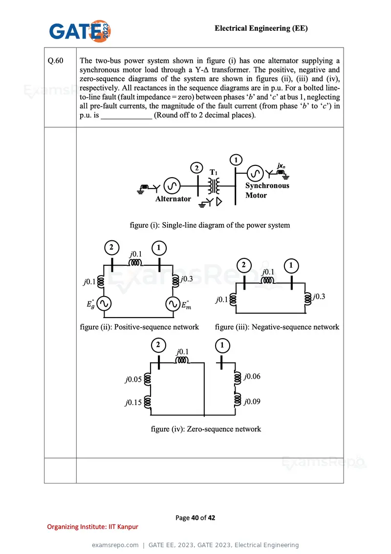
Text of page 40
Electrical Engineering (EE)


Q.60       The two-bus power system shown in figure (i) has one alternator supplying a
           synchronous motor load through a Y-Δ transformer. The positive, negative and
           zero-sequence diagrams of the system are shown in figures (ii), (iii) and (iv),
           respectively. All reactances in the sequence diagrams are in p.u. For a bolted line-
           to-line fault (fault impedance = zero) between phases ‘b’ and ‘c’ at bus 1, neglecting
           all pre-fault currents, the magnitude of the fault current (from phase ‘b’ to ‘c’) in
           p.u. is _____________ (Round off to 2 decimal places).


                                                                  1
                                                    2                                jxn
                                                        T1
                                                                      Synchronous
                                     Alternator                       Motor


                            figure (i): Single-line diagram of the power system

                     2               1
                             j0.1
                                                                      2                    1
                                                                              j0.1
            j0.1                             j0.3

                                                           j0.1                                j0.3
             Eg"                              "
                                             Em

           figure (ii): Positive-sequence network        figure (iii): Negative-sequence network

                                     2                       1
                                            j0.1


                           j0.05                                      j0.06


                           j0.15                                      j0.09


                                    figure (iv): Zero-sequence network


                                           Page 40 of 42
Organizing Institute: IIT Kanpur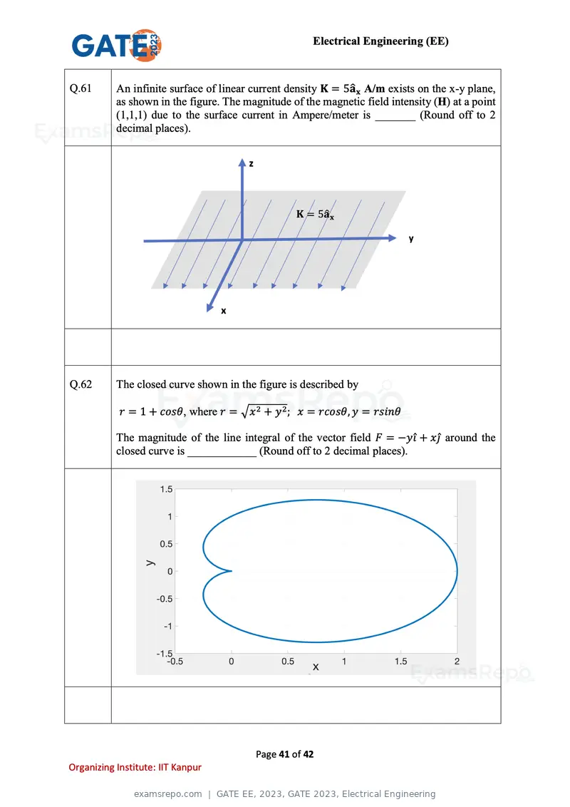
Text of page 41
Electrical Engineering (EE)


Q.61       An infinite surface of linear current density K = 5âx A/m exists on the x-y plane,
           as shown in the figure. The magnitude of the magnetic field intensity (H) at a point
           (1,1,1) due to the surface current in Ampere/meter is _______ (Round off to 2
           decimal places).


Q.62       The closed curve shown in the figure is described by

            r = 1 + cosθ, where r = √x 2 + y 2 ; x = rcosθ, y = rsinθ

           The magnitude of the line integral of the vector field F = −yî + xĵ around the
           closed curve is ____________ (Round off to 2 decimal places).


                                         Page 41 of 42
Organizing Institute: IIT Kanpur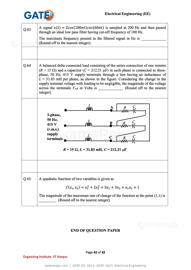
Text of page 42
Electrical Engineering (EE)
Q.63 A signal x(t) = 2cos(180πt)cos(60πt) is sampled at 200 Hz and then passed
through an ideal low pass filter having cut-off frequency of 100 Hz.
The maximum frequency present in the filtered signal in Hz is _____________
(Round off to the nearest integer).
Q.64 A balanced delta connected load consisting of the series connection of one resistor
(R = 15 ) and a capacitor (C = 212.21 F) in each phase is connected to three-
phase, 50 Hz, 415 V supply terminals through a line having an inductance of
L = 31.83 mH per phase, as shown in the figure. Considering the change in the
supply terminal voltage with loading to be negligible, the magnitude of the voltage
across the terminals VAB in Volts is _____________ (Round off to the nearest
integer).
L C
A R
3-phase,
50 Hz, L B R C
415 V
(r.m.s.)
supply L C R C
terminals
R = 15 , L = 31.83 mH, C = 212.21 F
Q.65 A quadratic function of two variables is given as
f(x1 , x2 ) = x12 + 2x22 + 3x1 + 3x2 + x1 x2 + 1
The magnitude of the maximum rate of change of the function at the point (1,1) is
_________ (Round off to the nearest integer).
END OF QUESTION PAPER
Page 42 of 42
Organizing Institute: IIT Kanpur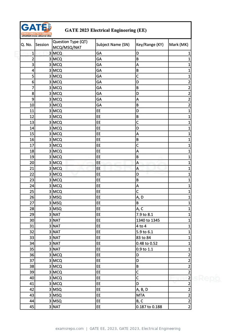
Text of page 1
GATE 2023 Electrical Engineering (EE)

                   Question Type (QT)
Q. No. Session                          Subject Name (SN)   Key/Range (KY)   Mark (MK)
                   MCQ/MSQ/NAT
     1           3 MCQ                  GA                  D                        1
     2           3 MCQ                  GA                  B                        1
     3           3 MCQ                  GA                  A                        1
     4           3 MCQ                  GA                  B                        1
     5           3 MCQ                  GA                  C                        1
     6           3 MCQ                  GA                  D                        2
     7           3 MCQ                  GA                  B                        2
     8           3 MCQ                  GA                  D                        2
     9           3 MCQ                  GA                  A                        2
    10           3 MCQ                  GA                  B                        2
    11           3 MCQ                  EE                  D                        1
    12           3 MCQ                  EE                  B                        1
    13           3 MCQ                  EE                  C                        1
    14           3 MCQ                  EE                  D                        1
    15           3 MCQ                  EE                  A                        1
    16           3 MCQ                  EE                  B                        1
    17           3 MCQ                  EE                  C                        1
    18           3 MCQ                  EE                  A                        1
    19           3 MCQ                  EE                  B                        1
    20           3 MCQ                  EE                  A                        1
    21           3 MCQ                  EE                  A                        1
    22           3 MCQ                  EE                  D                        1
    23           3 MCQ                  EE                  B                        1
    24           3 MCQ                  EE                  A                        1
    25           3 MCQ                  EE                  C                        1
    26           3 MSQ                  EE                  A, D                     1
    27           3 MSQ                  EE                  B                        1
    28           3 MSQ                  EE                  A, C                     1
    29           3 NAT                  EE                  7.9 to 8.1               1
    30           3 NAT                  EE                  1340 to 1345             1
    31           3 NAT                  EE                  4 to 4                   1
    32           3 NAT                  EE                  5.9 to 6.1               1
    33           3 NAT                  EE                  83 to 84                 1
    34           3 NAT                  EE                  0.48 to 0.52             1
    35           3 NAT                  EE                  0.9 to 1.1               1
    36           3 MCQ                  EE                  D                        2
    37           3 MCQ                  EE                  D                        2
    38           3 MCQ                  EE                  B                        2
    39           3 MCQ                  EE                  C                        2
    40           3 MCQ                  EE                  C                        2
    41           3 MCQ                  EE                  D                        2
    42           3 MSQ                  EE                  A, B, D                  2
    43           3 MSQ                  EE                  MTA                      2
    44           3 MSQ                  EE                  B, C                     2
    45           3 NAT                  EE                  0.187 to 0.188           2
Text of page 2
46   3 NAT   EE                 2 to 2           2
47   3 NAT   EE                 1.58 to 1.59     2
48   3 NAT   EE                 760 to 760       2
49   3 NAT   EE                 48 to 48         2
50   3 NAT   EE                 0.037 to 0.039   2
51   3 NAT   EE                 -12.1 to -11.9   2
52   3 NAT   EE                 237 to 239       2
53   3 NAT   EE                 2150 to 2250     2
54   3 NAT   EE                 1.56 to 1.58     2
55   3 NAT   EE                 7.1 to 7.5       2
56   3 NAT   EE                 8 to 8           2
57   3 NAT   EE                 2 to 2           2
58   3 NAT   EE                 39 to 40.5       2
59   3 NAT   EE                 245 to 255       2
60   3 NAT   EE                 7.1 to 7.3       2
61   3 NAT   EE                 2.49 to 2.51     2
62   3 NAT   EE                 9 to 10          2
63   3 NAT   EE                 80 to 80         2
64   3 NAT   EE                 414 to 416       2
65   3 NAT   EE                 10 to 10         2

             MTA=Marks to All
Page 1 of 42
Source: GATE. Question paper published by GATE.