
GATE EE 2026: Electrical Engineering

Text of page 1
Electrical Engineering (EE)


General Aptitude (GA)
Q.1 – Q.5 Carry ONE mark Each

 Q.1         ‘The shopkeeper sells lemons.’

             In this sentence, the word ‘lemons’ is the ________.


 (A)         object


 (B)         subject


 (C)         predicate


 (D)         verb


Organizing Institute: IIT Guwahati            Page 1 of 55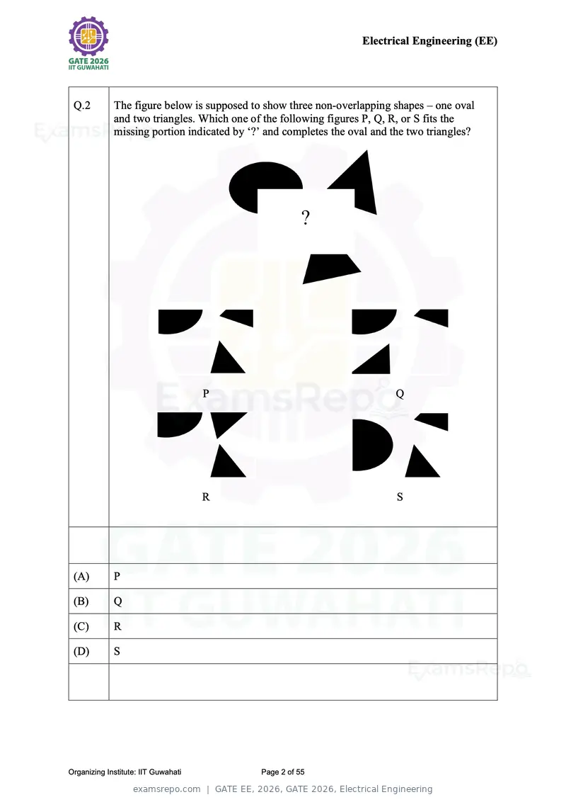
Text of page 2
Electrical Engineering (EE)


 Q.2         The figure below is supposed to show three non-overlapping shapes – one oval
             and two triangles. Which one of the following figures P, Q, R, or S fits the
             missing portion indicated by ‘?’ and completes the oval and the two triangles?


                                     P                                    Q


                                     R                                    S


 (A)         P

 (B)         Q

 (C)         R

 (D)         S


Organizing Institute: IIT Guwahati          Page 2 of 55
Text of page 3
Electrical Engineering (EE)


 Q.3         At how many points will the curves y = x 2 and y = −x 2 − 2x − 1 intersect in
             the real (x, y) plane?


 (A)         0


 (B)         1


 (C)         2


 (D)         3


Organizing Institute: IIT Guwahati          Page 3 of 55
Text of page 4
Electrical Engineering (EE)


 Q.4         ‘If Anish had scored hundred runs in today’s match, he would have been made the
             captain of his team. He would have then become the youngest captain in his
             team’s history. Unfortunately, he got out without scoring any runs. Hence, there
             won’t be any change in the captaincy for now.’

             Based on the paragraph above, which one of the following statements is true?


 (A)         Anish made hundred runs but was denied captaincy.


 (B)         Anish was the captain of his team before the game today.


 (C)         The current captain is older than Anish.


 (D)         Anish is the youngest player in his team.


Organizing Institute: IIT Guwahati           Page 4 of 55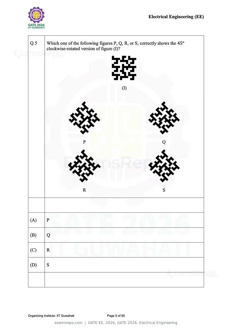
Text of page 5
Electrical Engineering (EE)


 Q.5         Which one of the following figures P, Q, R, or S, correctly shows the 45°
             clockwise-rotated version of figure (I)?


                                                       (I)


                                     P                                    Q


                                     R                                    S


 (A)         P


 (B)         Q


 (C)         R


 (D)         S


Organizing Institute: IIT Guwahati           Page 5 of 55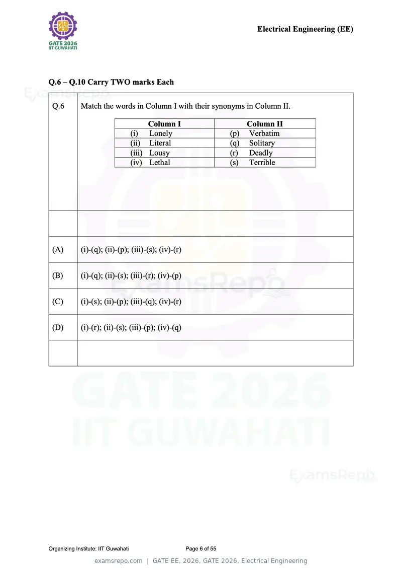
Text of page 6
Electrical Engineering (EE)


Q.6 – Q.10 Carry TWO marks Each

 Q.6         Match the words in Column I with their synonyms in Column II.

                                           Column I                      Column II
                                     (i) Lonely                      (p) Verbatim
                                     (ii) Literal                    (q) Solitary
                                     (iii) Lousy                     (r) Deadly
                                     (iv) Lethal                     (s) Terrible


 (A)         (i)-(q); (ii)-(p); (iii)-(s); (iv)-(r)


 (B)         (i)-(q); (ii)-(s); (iii)-(r); (iv)-(p)


 (C)         (i)-(s); (ii)-(p); (iii)-(q); (iv)-(r)


 (D)         (i)-(r); (ii)-(s); (iii)-(p); (iv)-(q)


Organizing Institute: IIT Guwahati                    Page 6 of 55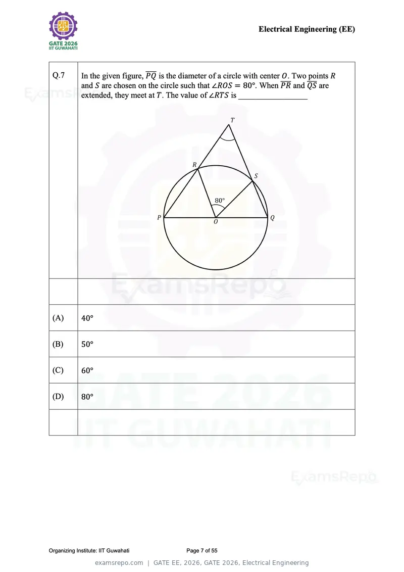
Text of page 7
Electrical Engineering (EE)


 Q.7                              ̅̅̅̅ is the diameter of a circle with center O. Two points R
             In the given figure, PQ
             and S are chosen on the circle such that ∠ROS = 80°. When ̅̅̅̅   PR and ̅̅̅̅
                                                                                     QS are
             extended, they meet at T. The value of ∠RTS is _________________


 (A)         40°


 (B)         50°


 (C)         60°


 (D)         80°


Organizing Institute: IIT Guwahati            Page 7 of 55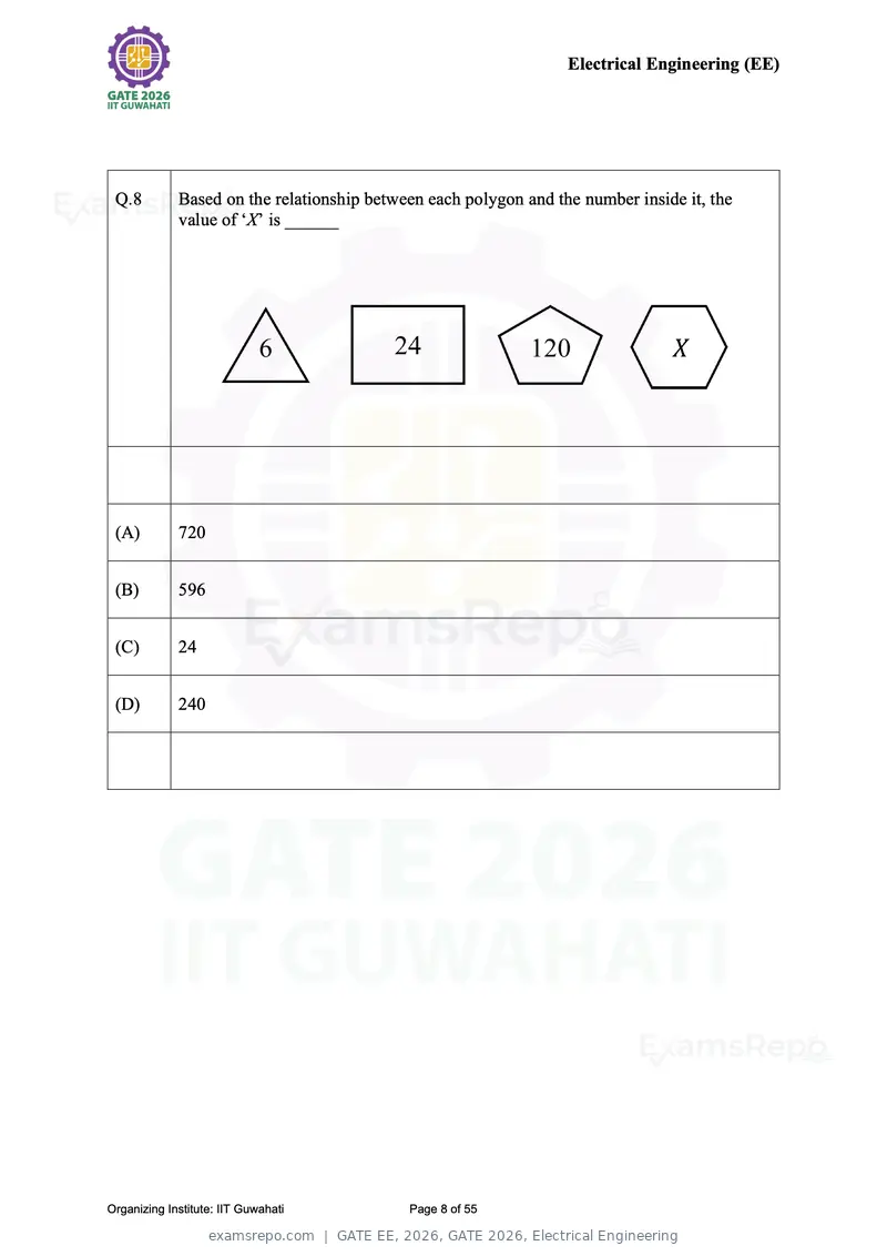
Text of page 8
Electrical Engineering (EE)


 Q.8         Based on the relationship between each polygon and the number inside it, the
             value of ‘X’ is ______


 (A)         720


 (B)         596


 (C)         24


 (D)         240


Organizing Institute: IIT Guwahati          Page 8 of 55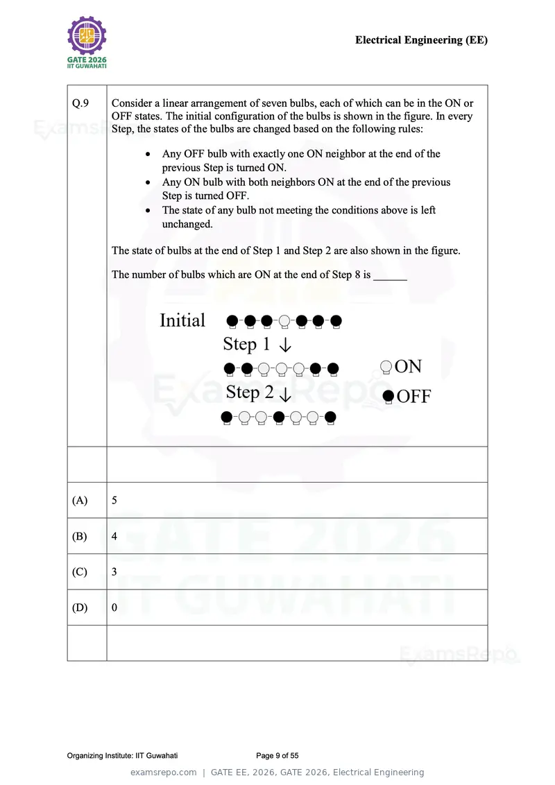
Text of page 9
Electrical Engineering (EE)
Q.9 Consider a linear arrangement of seven bulbs, each of which can be in the ON or
OFF states. The initial configuration of the bulbs is shown in the figure. In every
Step, the states of the bulbs are changed based on the following rules:
Any OFF bulb with exactly one ON neighbor at the end of the
previous Step is turned ON.
Any ON bulb with both neighbors ON at the end of the previous
Step is turned OFF.
The state of any bulb not meeting the conditions above is left
unchanged.
The state of bulbs at the end of Step 1 and Step 2 are also shown in the figure.
The number of bulbs which are ON at the end of Step 8 is ______
(A) 5
(B) 4
(C) 3
(D) 0
Organizing Institute: IIT Guwahati Page 9 of 55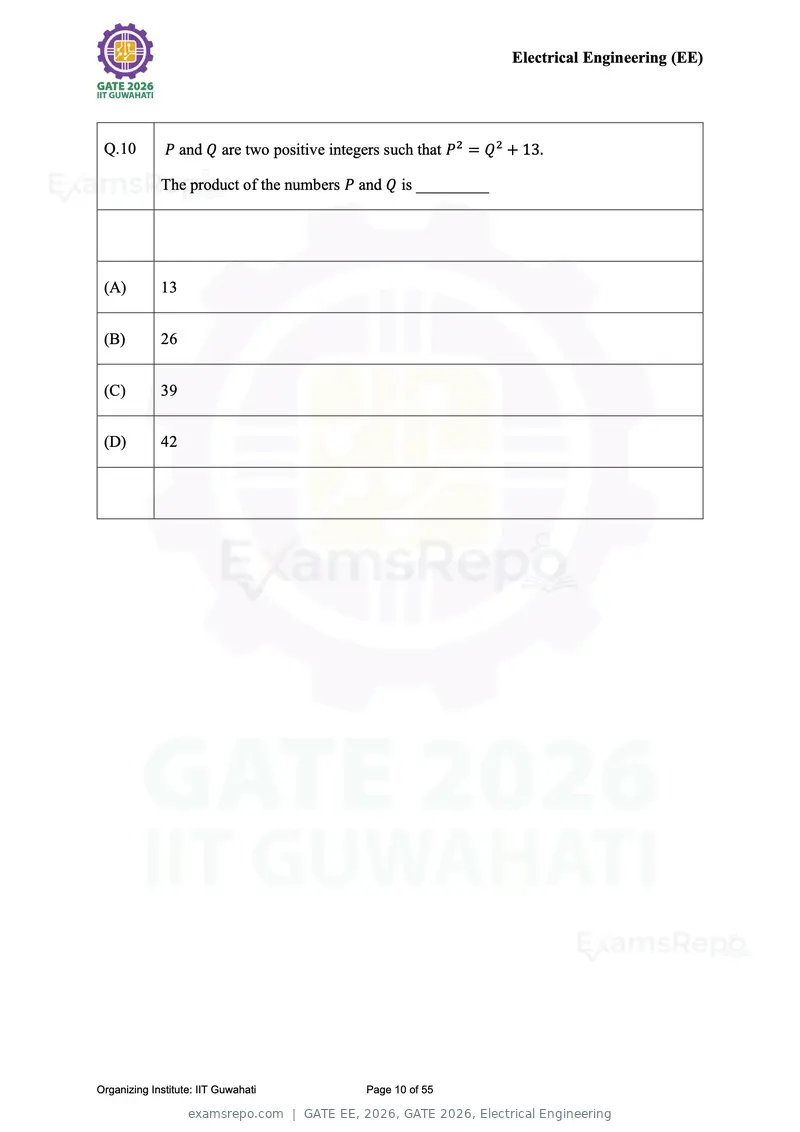
Text of page 10
Electrical Engineering (EE)


 Q.10         P and Q are two positive integers such that P2 = Q 2 + 13.

             The product of the numbers P and Q is _________


 (A)         13


 (B)         26


 (C)         39


 (D)         42


Organizing Institute: IIT Guwahati          Page 10 of 55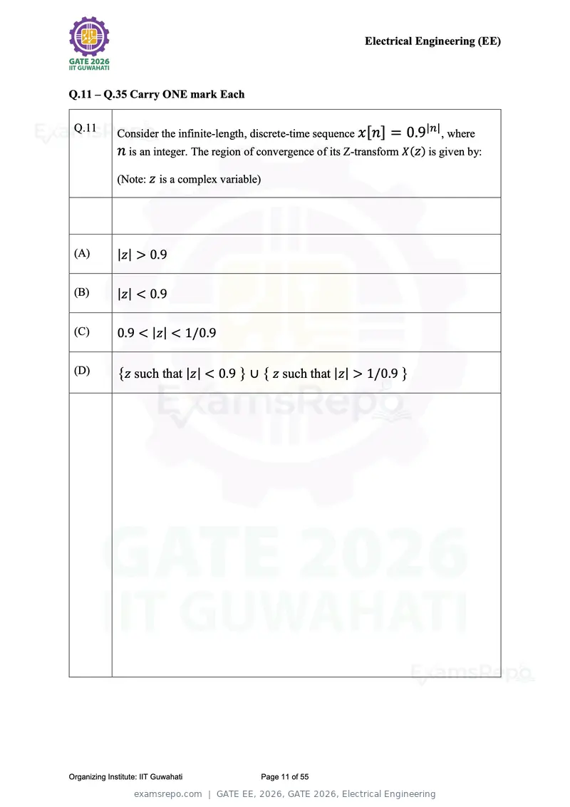
Text of page 11
Electrical Engineering (EE)


Q.11 – Q.35 Carry ONE mark Each

 Q.11                                                                            |n|
              Consider the infinite-length, discrete-time sequence x [n] = 0.9         , where
              n is an integer. The region of convergence of its Z-transform X(z) is given by:
              (Note: z is a complex variable)


 (A)          |z| > 0.9

 (B)          |z| < 0.9

 (C)          0.9 < |z| < 1/0.9

 (D)          {z such that |z| < 0.9 } ∪ { z such that |z| > 1/0.9 }


Organizing Institute: IIT Guwahati           Page 11 of 55
Text of page 12
Electrical Engineering (EE)


 Q.12         Let xc (t) be any continuous-time periodic signal with period T . It is sampled
              uniformly with a sampling period Ts where Ts ≠ T , resulting in the discrete
              sequence

              x [n] = xc (nTs ), where n is an integer.
              Which one of the following statements is correct about x [n]?


 (A)          x [n] will always be periodic with period T/Ts for all values of T/Ts

  (B)         x [n] will always be periodic with period 1 for all values of T/Ts

 (C)          x [n] will never be periodic

 (D)          x [n] will be periodic if and only if T/Ts is a rational number


Organizing Institute: IIT Guwahati           Page 12 of 55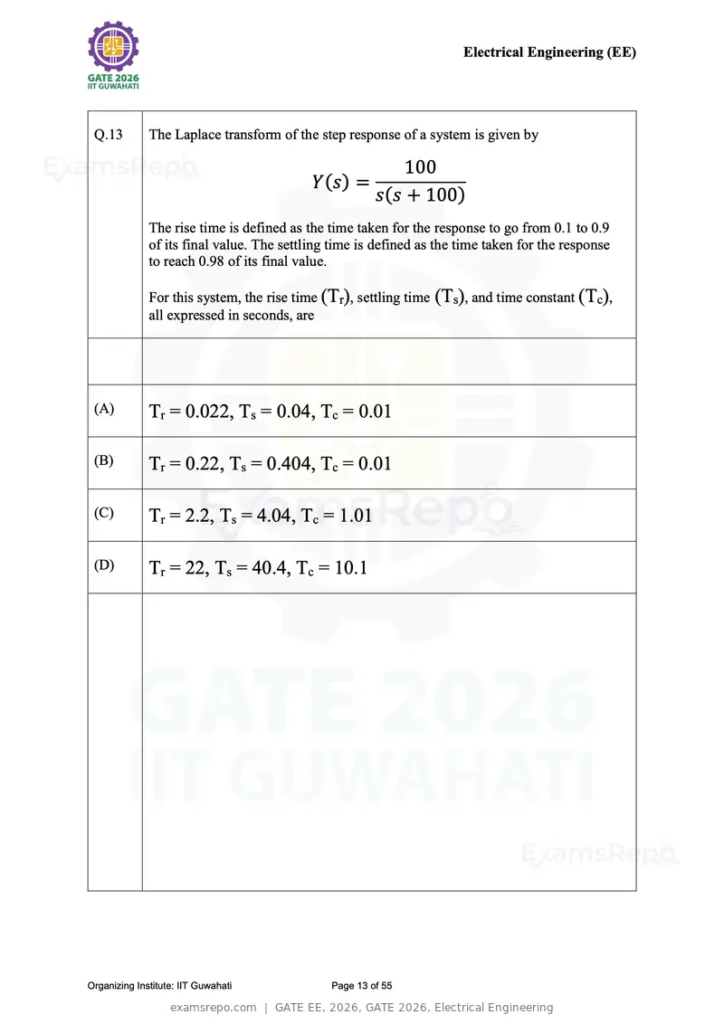
Text of page 13
Electrical Engineering (EE)


 Q.13         The Laplace transform of the step response of a system is given by

                                                           100
                                           Y(s) =
                                                       s(s + 100)
              The rise time is defined as the time taken for the response to go from 0.1 to 0.9
              of its final value. The settling time is defined as the time taken for the response
              to reach 0.98 of its final value.

              For this system, the rise time (Tr), settling time (Ts), and time constant (Tc),
              all expressed in seconds, are


 (A)          Tr = 0.022, Ts = 0.04, Tc = 0.01

 (B)          Tr = 0.22, Ts = 0.404, Tc = 0.01

 (C)          Tr = 2.2, Ts = 4.04, Tc = 1.01

 (D)          Tr = 22, Ts = 40.4, Tc = 10.1


Organizing Institute: IIT Guwahati            Page 13 of 55
Text of page 14
Electrical Engineering (EE)


 Q.14         Consider the following differential equation:

                                             d2 y     dy
                                        t2      2
                                                  + 7t + 8ty = 10 sin(t)
                                             dt       dt
              Which one of the following options is correct?


 (A)          It is a linear differential equation


 (B)          It is a nonlinear differential equation


 (C)          It is a time-invariant differential equation


 (D)          It is a second-order partial differential equation


Organizing Institute: IIT Guwahati              Page 14 of 55
Text of page 15
Electrical Engineering (EE)


 Q.15         A uniform ring charge of radius R carries a total charge Q. Which one of the
              following options correctly quantifies the magnitude of the force on a point
              charge of strength q kept at the center of the ring?

              (ε is the permittivity of the medium)


 (A)           Qq
              4πεR

 (B)           Qq
              4πεR 2

 (C)             0


 (D)            q     Q
                   ×
              4πεR   2πR


Organizing Institute: IIT Guwahati           Page 15 of 55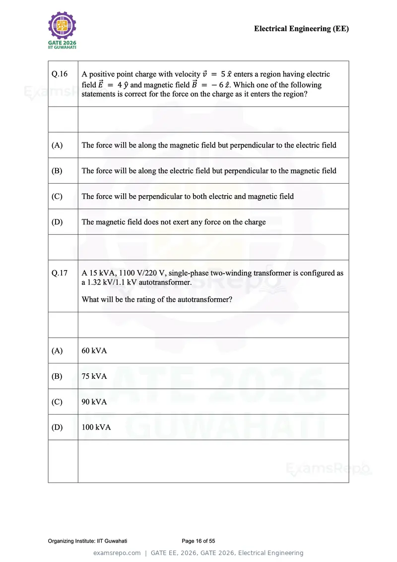
Text of page 16
Electrical Engineering (EE)


 Q.16         A positive point charge with velocity v⃗ = 5 x̂ enters a region having electric
              field E⃗⃗ = 4 ŷ and magnetic field B⃗⃗ = − 6 ẑ . Which one of the following
              statements is correct for the force on the charge as it enters the region?


 (A)          The force will be along the magnetic field but perpendicular to the electric field


 (B)          The force will be along the electric field but perpendicular to the magnetic field


 (C)          The force will be perpendicular to both electric and magnetic field


 (D)          The magnetic field does not exert any force on the charge


 Q.17         A 15 kVA, 1100 V/220 V, single-phase two-winding transformer is configured as
              a 1.32 kV/1.1 kV autotransformer.

              What will be the rating of the autotransformer?


 (A)          60 kVA


 (B)          75 kVA


 (C)          90 kVA


 (D)          100 kVA


Organizing Institute: IIT Guwahati            Page 16 of 55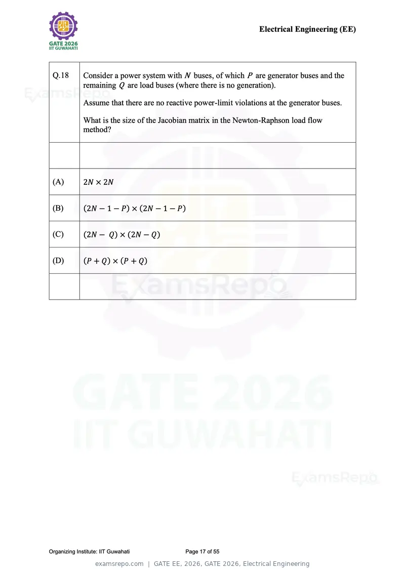
Text of page 17
Electrical Engineering (EE)


 Q.18         Consider a power system with N buses, of which P are generator buses and the
              remaining Q are load buses (where there is no generation).

              Assume that there are no reactive power-limit violations at the generator buses.

              What is the size of the Jacobian matrix in the Newton-Raphson load flow
              method?


 (A)          2N × 2N


 (B)          (2N − 1 − P) × (2N − 1 − P)


 (C)          (2N − Q) × (2N − Q)


 (D)          (P + Q) × (P + Q)


Organizing Institute: IIT Guwahati           Page 17 of 55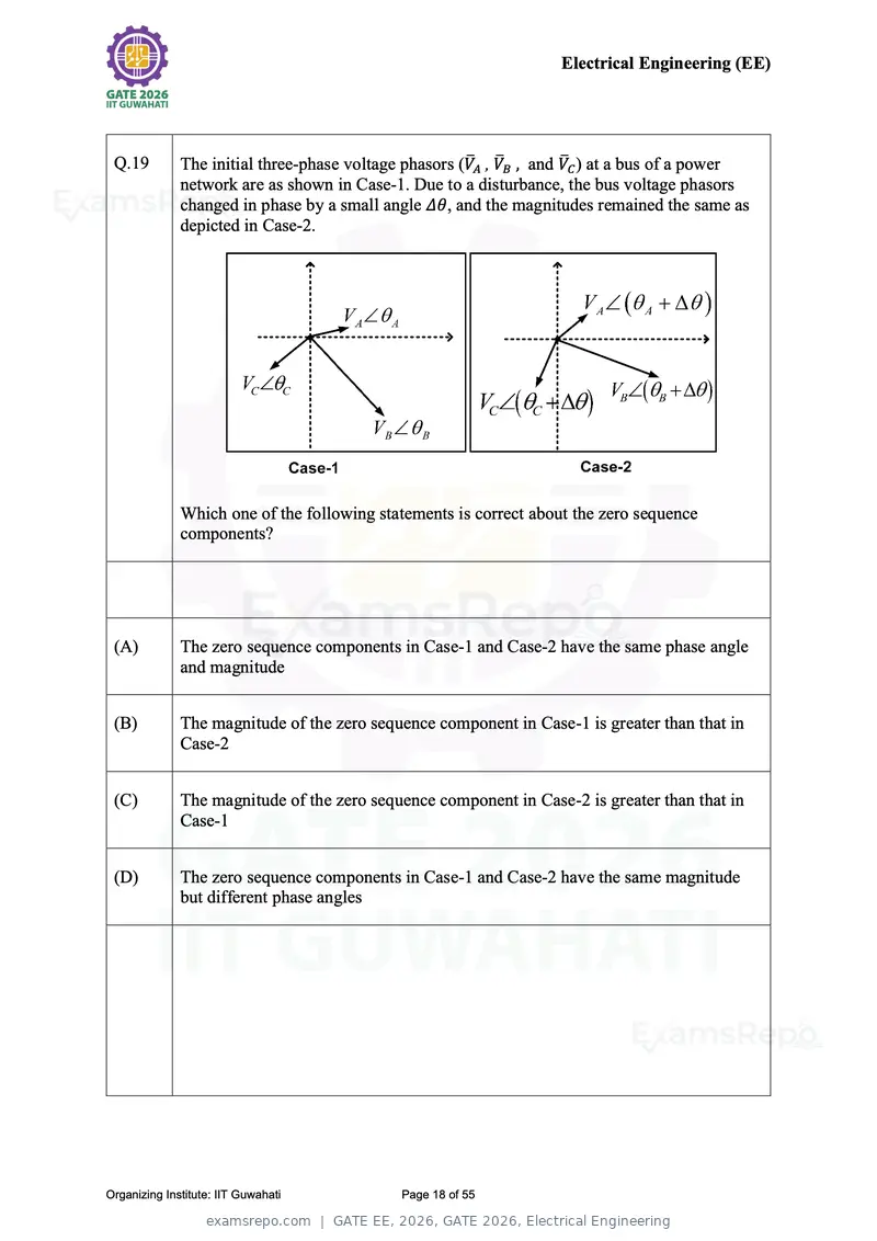
Text of page 18
Electrical Engineering (EE)


 Q.19         The initial three-phase voltage phasors (V̅A , V̅B , and V̅C ) at a bus of a power
              network are as shown in Case-1. Due to a disturbance, the bus voltage phasors
              changed in phase by a small angle Δθ, and the magnitudes remained the same as
              depicted in Case-2.


              Which one of the following statements is correct about the zero sequence
              components?


 (A)          The zero sequence components in Case-1 and Case-2 have the same phase angle
              and magnitude


 (B)          The magnitude of the zero sequence component in Case-1 is greater than that in
              Case-2


 (C)          The magnitude of the zero sequence component in Case-2 is greater than that in
              Case-1


 (D)          The zero sequence components in Case-1 and Case-2 have the same magnitude
              but different phase angles


Organizing Institute: IIT Guwahati           Page 18 of 55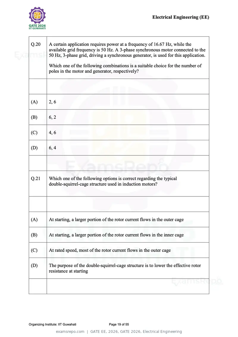
Text of page 19
Electrical Engineering (EE)


 Q.20         A certain application requires power at a frequency of 16.67 Hz, while the
              available grid frequency is 50 Hz. A 3-phase synchronous motor connected to the
              50 Hz, 3-phase grid, driving a synchronous generator, is used for this application.

              Which one of the following combinations is a suitable choice for the number of
              poles in the motor and generator, respectively?


 (A)          2, 6


 (B)          6, 2


 (C)          4, 6


 (D)          6, 4


 Q.21         Which one of the following options is correct regarding the typical
              double-squirrel-cage structure used in induction motors?


 (A)          At starting, a larger portion of the rotor current flows in the outer cage


 (B)          At starting, a larger portion of the rotor current flows in the inner cage


 (C)          At rated speed, most of the rotor current flows in the outer cage


 (D)          The purpose of the double-squirrel-cage structure is to lower the effective rotor
              resistance at starting


Organizing Institute: IIT Guwahati             Page 19 of 55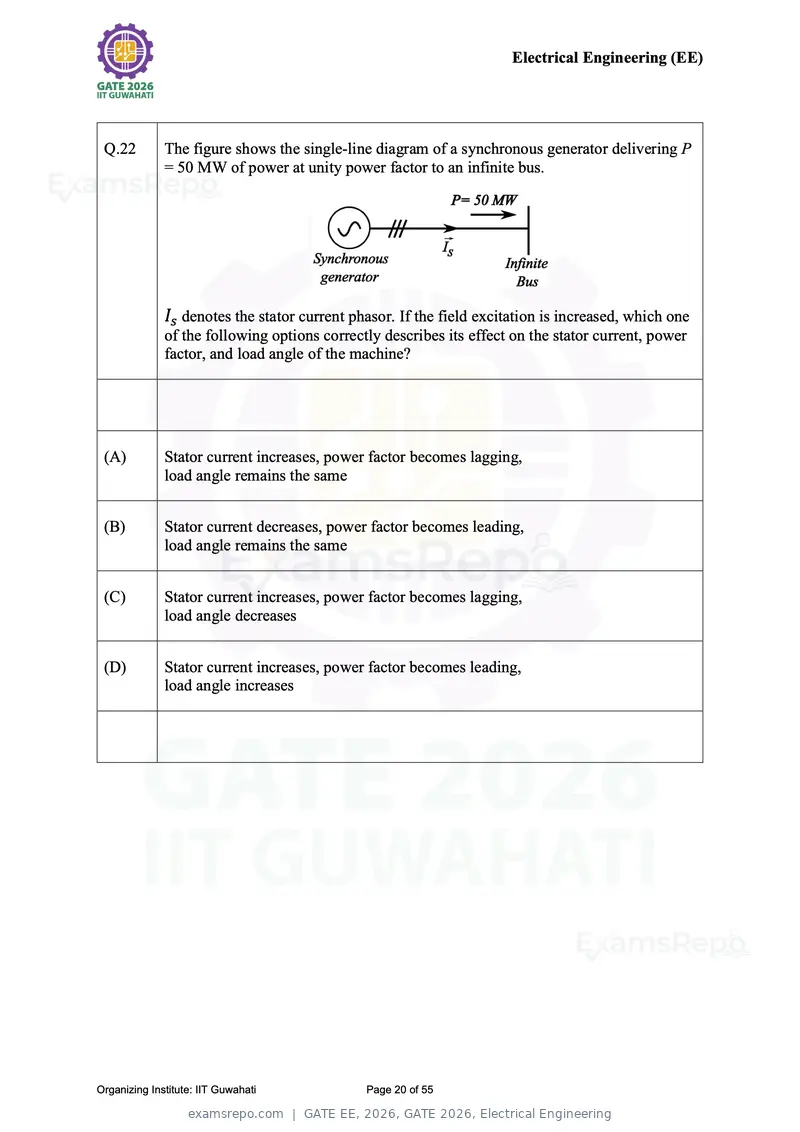
Text of page 20
Electrical Engineering (EE)


 Q.22         The figure shows the single-line diagram of a synchronous generator delivering P
              = 50 MW of power at unity power factor to an infinite bus.


              Is denotes the stator current phasor. If the field excitation is increased, which one
              of the following options correctly describes its effect on the stator current, power
              factor, and load angle of the machine?


 (A)          Stator current increases, power factor becomes lagging,
              load angle remains the same


 (B)          Stator current decreases, power factor becomes leading,
              load angle remains the same


 (C)          Stator current increases, power factor becomes lagging,
              load angle decreases


 (D)          Stator current increases, power factor becomes leading,
              load angle increases


Organizing Institute: IIT Guwahati            Page 20 of 55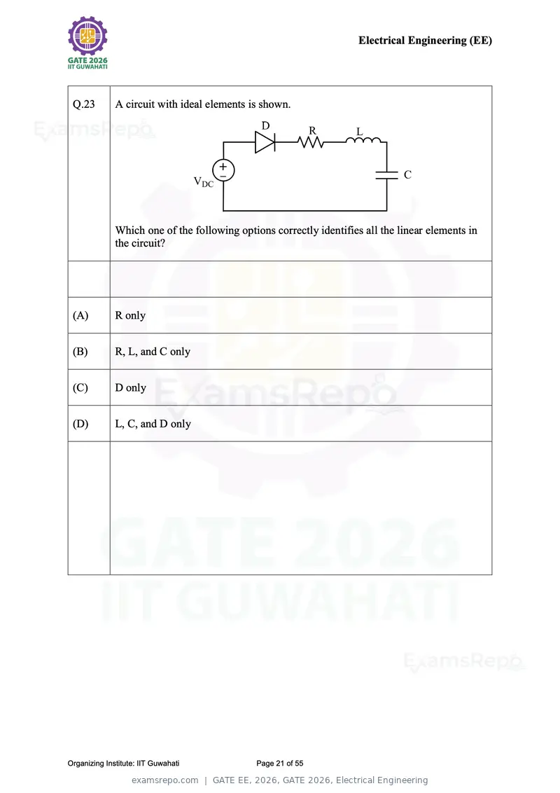
Text of page 21
Electrical Engineering (EE)


 Q.23         A circuit with ideal elements is shown.


              Which one of the following options correctly identifies all the linear elements in
              the circuit?


 (A)          R only


 (B)          R, L, and C only


 (C)          D only


 (D)          L, C, and D only


Organizing Institute: IIT Guwahati            Page 21 of 55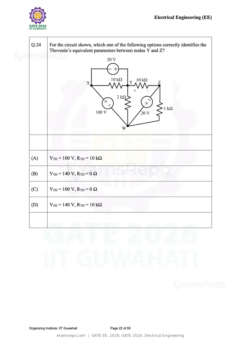
Text of page 22
Electrical Engineering (EE)


 Q.24         For the circuit shown, which one of the following options correctly identifies the
              Thevenin’s equivalent parameters between nodes Y and Z?


 (A)          VTH = 100 V, RTH = 10 kΩ


 (B)          VTH = 140 V, RTH = 0 Ω


 (C)          VTH = 100 V, RTH = 0 Ω


 (D)          VTH = 140 V, RTH = 10 kΩ


Organizing Institute: IIT Guwahati           Page 22 of 55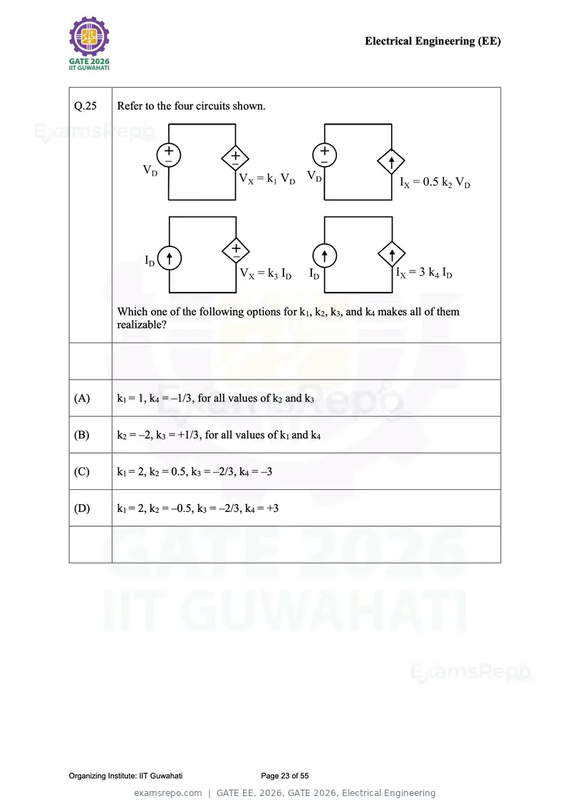
Text of page 23
Electrical Engineering (EE)


 Q.25         Refer to the four circuits shown.


              Which one of the following options for k1, k2, k3, and k4 makes all of them
              realizable?


 (A)          k1 = 1, k4 = –1/3, for all values of k2 and k3


 (B)          k2 = –2, k3 = +1/3, for all values of k1 and k4


 (C)          k1 = 2, k2 = 0.5, k3 = –2/3, k4 = –3


 (D)          k1 = 2, k2 = –0.5, k3 = –2/3, k4 = +3


Organizing Institute: IIT Guwahati             Page 23 of 55
Text of page 24
Electrical Engineering (EE)


 Q.26         A single-phase voltage source vs = 325 sin(2π50t) V delivers a current,
              i = 12 sin(2π50t) + 9 sin(2π150t) A to a load.

              The load power factor, correct up to two decimal places, is:


 (A)          1.00


 (B)          0.80


 (C)          0.65


 (D)          0.57


Organizing Institute: IIT Guwahati           Page 24 of 55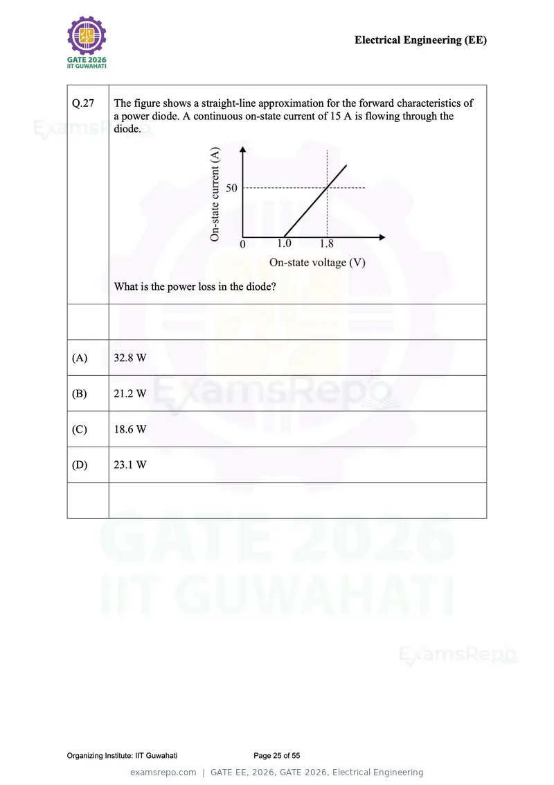
Text of page 25
Electrical Engineering (EE)


 Q.27         The figure shows a straight-line approximation for the forward characteristics of
              a power diode. A continuous on-state current of 15 A is flowing through the
              diode.


              What is the power loss in the diode?


 (A)          32.8 W


 (B)          21.2 W


 (C)          18.6 W


 (D)          23.1 W


Organizing Institute: IIT Guwahati           Page 25 of 55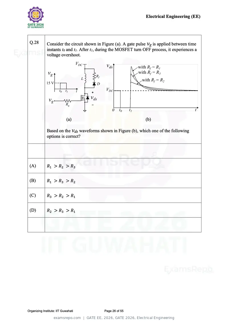
Text of page 26
Electrical Engineering (EE)


 Q.28         Consider the circuit shown in Figure (a). A gate pulse vg is applied between time
              instants t0 and t1. After t1, during the MOSFET turn OFF process, it experiences a
              voltage overshoot.


                             (a)                                    (b)

              Based on the vds waveforms shown in Figure (b), which one of the following
              options is correct?


 (A)          R1 > R2 > R3


 (B)          R1 > R3 > R2


 (C)          R3 > R2 > R1


 (D)          R2 > R3 > R1


Organizing Institute: IIT Guwahati           Page 26 of 55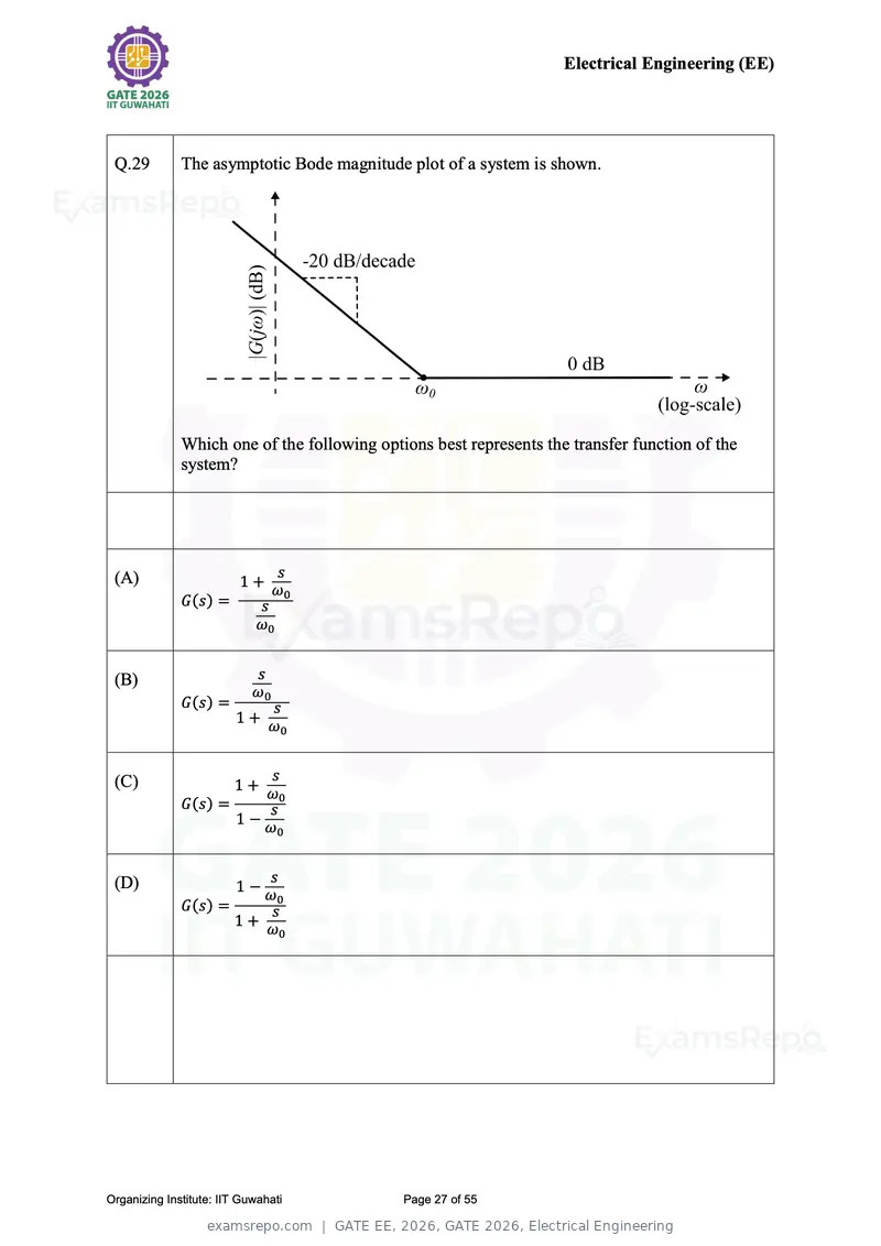
Text of page 27
Electrical Engineering (EE)


 Q.29         The asymptotic Bode magnitude plot of a system is shown.


              Which one of the following options best represents the transfer function of the
              system?


 (A)                             s
                         1+
                                 ω0
              G(s) =        s
                            ω0


 (B)                        s
                            ω0
              G(s) =        s
                         1+ ω
                                 0


 (C)                       s
                        1+ ω
                                 0
              G(s) =        s
                         1−
                            ω0


 (D)                    s
                     1−ω
                         0
              G(s) =    s
                     1+ ω
                          0


Organizing Institute: IIT Guwahati           Page 27 of 55
Text of page 28
Electrical Engineering (EE)


 Q.30         Two n × n matrices A and B have a common eigenvalue 2, and the same
              corresponding nonzero eigenvector.

              Which of the following options is/are correct?

              (Note: I is the n × n identity matrix.)


 (A)          Determinant ( A − 2I ) = 0


 (B)          Determinant ( B − 2I ) = 0


 (C)          Determinant ( A + B − 2I ) = 0


 (D)          Determinant ( A + B − 4I ) = 0


Organizing Institute: IIT Guwahati           Page 28 of 55
Text of page 29
Electrical Engineering (EE)


 Q.31         A 220V/12V single-phase transformer is designed for use in India and rated
              100 VA at 50 Hz. Later, this unit is shipped to the USA where it is used as a
              110V/6V transformer at 60 Hz.

              Which of the following statements is/are correct?


 (A)          No-load current drawn would be smaller for operation in the USA compared to
              that in India


 (B)          For the same load current, the losses would be higher in the USA compared to
              that in India


 (C)          The peak magnetic flux density in the core would be higher while operating in the
              USA compared to that in India


 (D)          The eddy current losses in the core would be approximately 44% higher while
              operating in the USA compared to that in India


Organizing Institute: IIT Guwahati           Page 29 of 55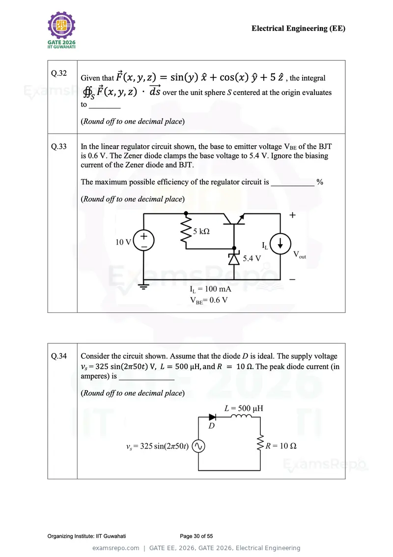
Text of page 30
Electrical Engineering (EE)


 Q.32                    ⃗ (x, y, z) = sin(y) x̂ + cos(x ) ŷ + 5 ẑ , the integral
              Given that F
               ∯S F⃗ (x, y, z) ∙ ⃗⃗⃗⃗⃗
                                 ds over the unit sphere S centered at the origin evaluates
              to ________

              (Round off to one decimal place)


 Q.33         In the linear regulator circuit shown, the base to emitter voltage VBE of the BJT
              is 0.6 V. The Zener diode clamps the base voltage to 5.4 V. Ignore the biasing
              current of the Zener diode and BJT.

              The maximum possible efficiency of the regulator circuit is ___________ %

              (Round off to one decimal place)


 Q.34         Consider the circuit shown. Assume that the diode D is ideal. The supply voltage
              vs = 325 sin(2π50t) V, L = 500 µH, and R = 10 Ω. The peak diode current (in
              amperes) is ______________

              (Round off to one decimal place)


Organizing Institute: IIT Guwahati           Page 30 of 55
Text of page 31
Electrical Engineering (EE)


 Q.35         A is an m×m skew-symmetric matrix with real-valued entries, and x is an
              m-dimensional column vector with real-valued entries such that xTx = 1.
              The quantity xTAx evaluates to _________

              (Answer in integer)


Organizing Institute: IIT Guwahati       Page 31 of 55
Text of page 32
Electrical Engineering (EE)


Q.36 – Q.65 Carry TWO marks Each

 Q.36       A time-limited waveform g(x) is specified as follows:

                    −k,              −π < x ≤0
            g(x) = { +k,             0 < x ≤π
                      0,             otherwise

            A new waveform f(x) is constructed from g(x) as follows:
                                       ∞

                                f(x) = ∑ g(x + 2πm),            for all x ∈ R
                                     m=−∞

            The sum of the coefficients of the third harmonics of the sine and cosine
                                                                             2
            terms in the trigonometric Fourier series expansion of f(x) is      .
                                                                            3π


            What is the value of k ?


 (A)        1


 (B)        1
            2

 (C)        1
            3

 (D)        1
            4


Organizing Institute: IIT Guwahati           Page 32 of 55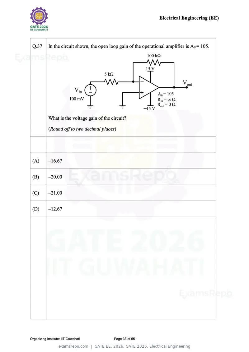
Text of page 33
Electrical Engineering (EE)


 Q.37       In the circuit shown, the open loop gain of the operational amplifier is A0 = 105.


            What is the voltage gain of the circuit?

            (Round off to two decimal places)


 (A)        –16.67


 (B)        –20.00


 (C)        –21.00


 (D)        –12.67


Organizing Institute: IIT Guwahati           Page 33 of 55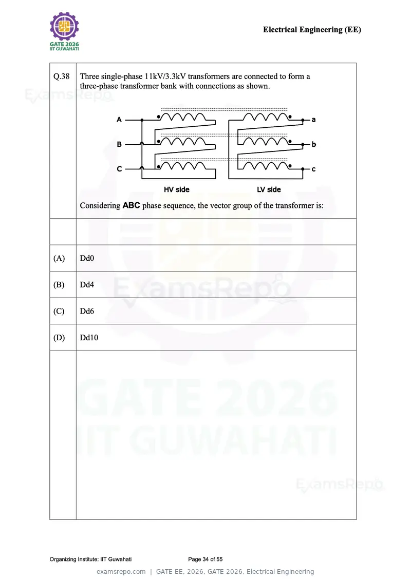
Text of page 34
Electrical Engineering (EE)


 Q.38       Three single-phase 11kV/3.3kV transformers are connected to form a
            three-phase transformer bank with connections as shown.


            Considering ABC phase sequence, the vector group of the transformer is:


 (A)        Dd0


 (B)        Dd4


 (C)        Dd6


 (D)        Dd10


Organizing Institute: IIT Guwahati         Page 34 of 55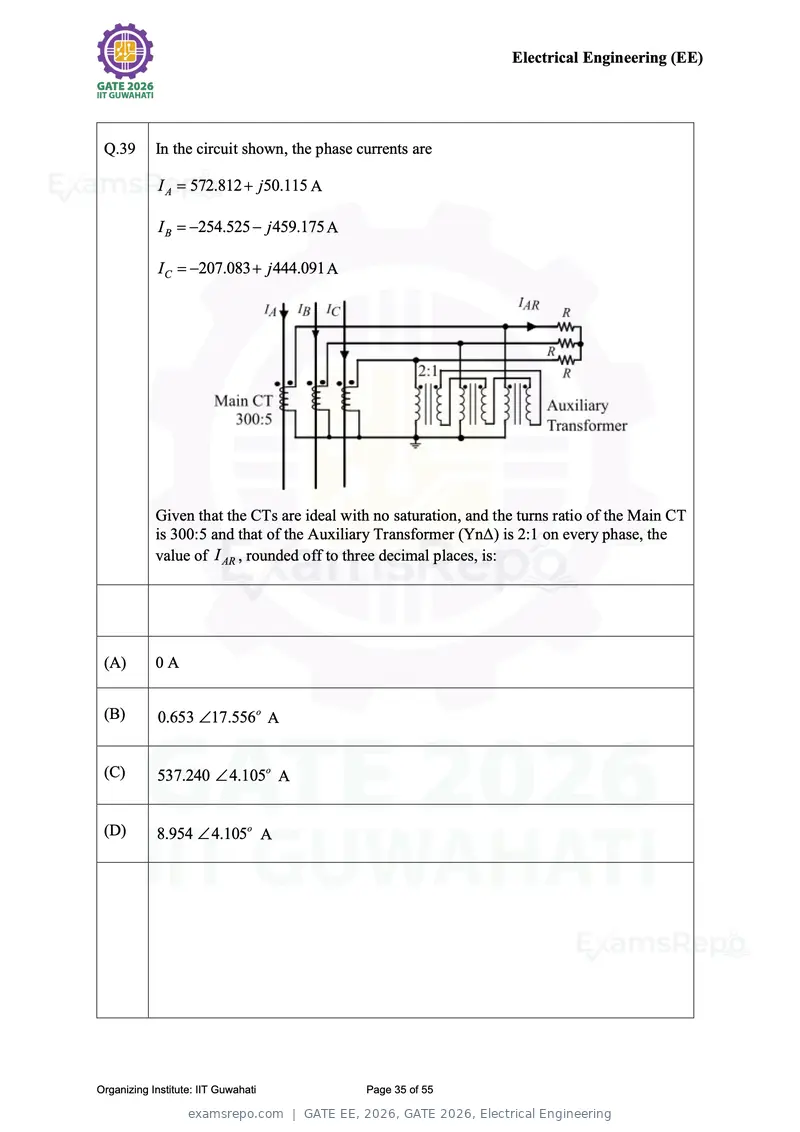
Text of page 35
Electrical Engineering (EE)
Q.39 In the circuit shown, the phase currents are
I A 572.812 j50.115 A
I B 254.525 j 459.175 A
IC 207.083 j 444.091 A
Given that the CTs are ideal with no saturation, and the turns ratio of the Main CT
is 300:5 and that of the Auxiliary Transformer (ΥnΔ) is 2:1 on every phase, the
value of I AR , rounded off to three decimal places, is:
(A) 0A
(B) 0.653 17.556o A
(C) 537.240 4.105o A
(D) 8.954 4.105o A
Organizing Institute: IIT Guwahati Page 35 of 55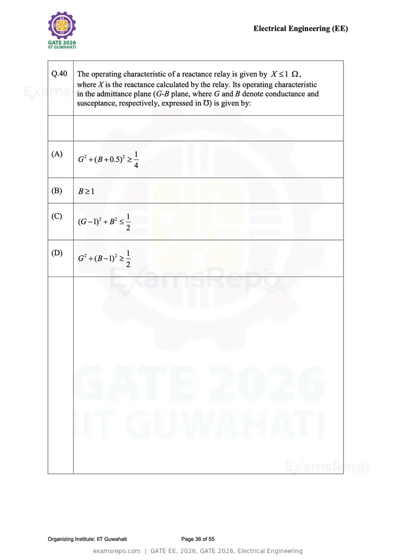
Text of page 36
Electrical Engineering (EE)
Q.40 The operating characteristic of a reactance relay is given by X 1 ,
where X is the reactance calculated by the relay. Its operating characteristic
in the admittance plane (G-B plane, where G and B denote conductance and
susceptance, respectively, expressed in Ʊ) is given by:
(A) 1
G 2 ( B 0.5)2
4
(B) B 1
(C) 1
(G 1)2 B 2
2
(D) 1
G 2 ( B 1)2
2
Organizing Institute: IIT Guwahati Page 36 of 55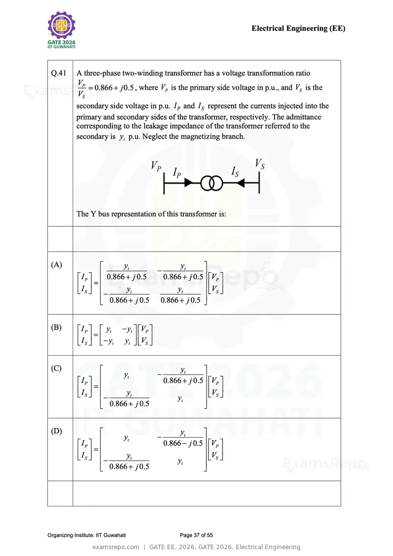
Text of page 37
Electrical Engineering (EE)
Q.41 A three-phase two-winding transformer has a voltage transformation ratio
VP
0.866 j 0.5 , where VP is the primary side voltage in p.u., and VS is the
VS
secondary side voltage in p.u. I P and I S represent the currents injected into the
primary and secondary sides of the transformer, respectively. The admittance
corresponding to the leakage impedance of the transformer referred to the
secondary is yt p.u. Neglect the magnetizing branch.
The Y bus representation of this transformer is:
(A) yt yt
IP 0.866 j 0.5 0.866 j 0.5 VP
I S yt yt VS
0.866 j 0.5 0.866 j 0.5
(B) I P yt yt VP
I y yt VS
S t
(C) yt
yt
IP 0.866 j 0.5 VP
I
S y t VS
0.866 j 0.5 yt
(D) yt
yt
IP 0.866 j 0.5 VP
I
S yt
yt
VS
0.866 j 0.5
Organizing Institute: IIT Guwahati Page 37 of 55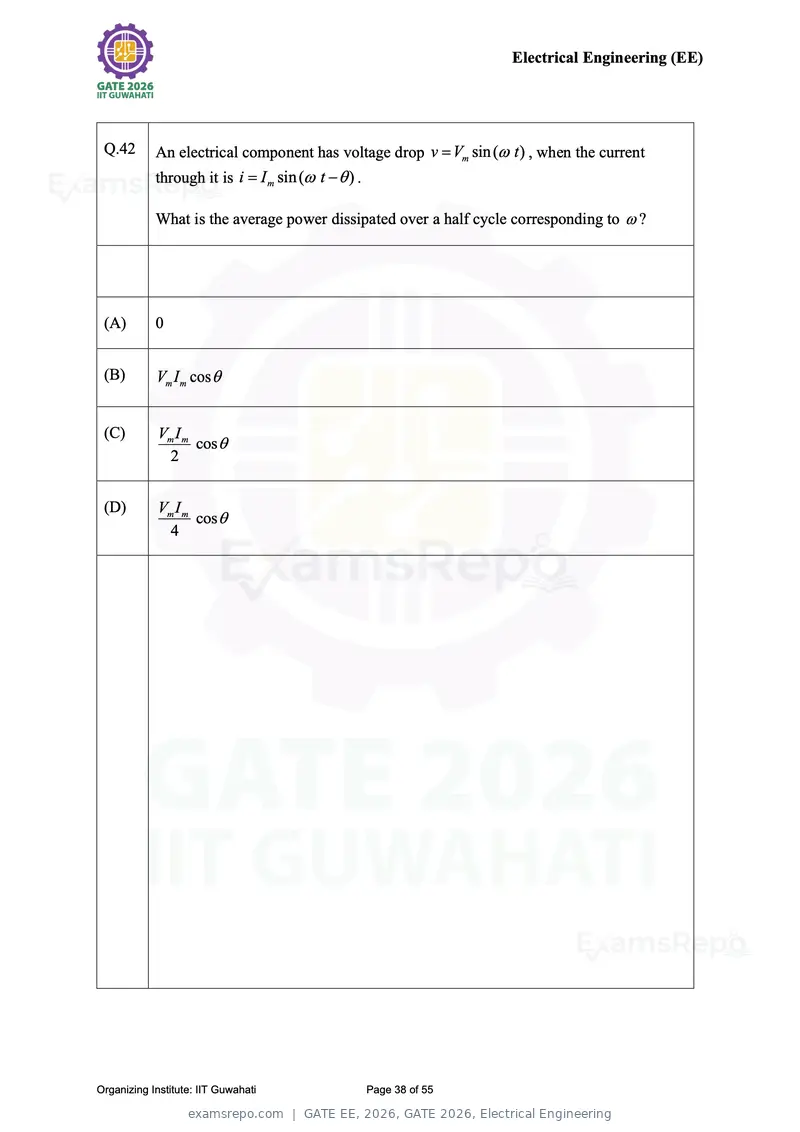
Text of page 38
Electrical Engineering (EE)
Q.42 An electrical component has voltage drop v Vm sin ( t ) , when the current
through it is i I m sin ( t ) .
What is the average power dissipated over a half cycle corresponding to ?
(A) 0
(B) Vm I m cos
(C) Vm I m
cos
2
(D) Vm I m
cos
4
Organizing Institute: IIT Guwahati Page 38 of 55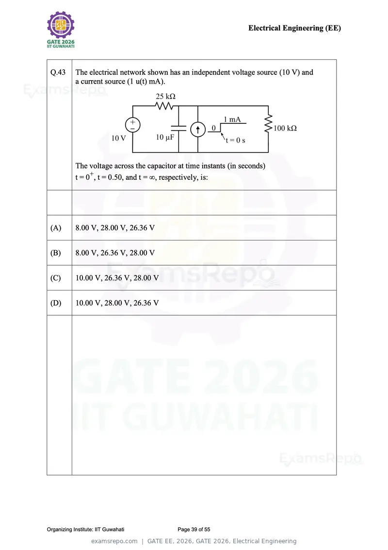
Text of page 39
Electrical Engineering (EE)


 Q.43       The electrical network shown has an independent voltage source (10 V) and
            a current source (1 u(t) mA).


            The voltage across the capacitor at time instants (in seconds)
            t = 0+, t = 0.50, and t = ∞, respectively, is:


 (A)        8.00 V, 28.00 V, 26.36 V


 (B)        8.00 V, 26.36 V, 28.00 V


 (C)        10.00 V, 26.36 V, 28.00 V


 (D)        10.00 V, 28.00 V, 26.36 V


Organizing Institute: IIT Guwahati           Page 39 of 55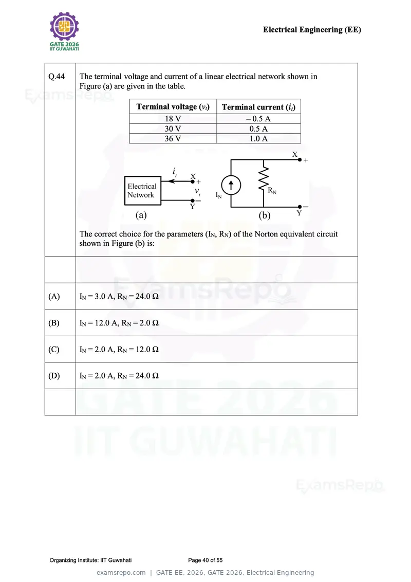
Text of page 40
Electrical Engineering (EE)


Q.44        The terminal voltage and current of a linear electrical network shown in
            Figure (a) are given in the table.

                                     Terminal voltage (vt)     Terminal current (it)
                                           18 V                      – 0.5 A
                                           30 V                       0.5 A
                                           36 V                       1.0 A


            The correct choice for the parameters (IN, RN) of the Norton equivalent circuit
            shown in Figure (b) is:


(A)         IN = 3.0 A, RN = 24.0 Ω


(B)         IN = 12.0 A, RN = 2.0 Ω


(C)         IN = 2.0 A, RN = 12.0 Ω


(D)         IN = 2.0 A, RN = 24.0 Ω


Organizing Institute: IIT Guwahati                 Page 40 of 55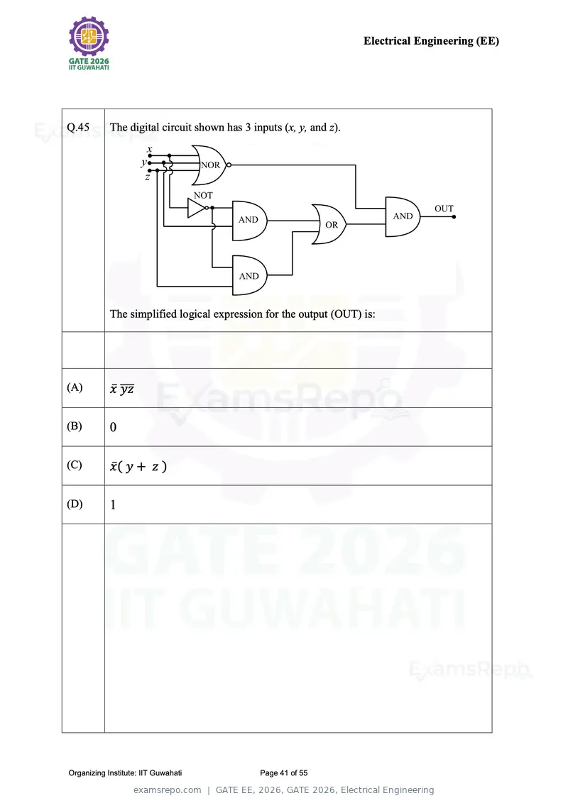
Text of page 41
Electrical Engineering (EE)


Q.45        The digital circuit shown has 3 inputs (x, y, and z).


            The simplified logical expression for the output (OUT) is:


(A)         x̅ ̅̅̅
               yz

(B)         0

(C)         x̅ ( y + z )

(D)         1


Organizing Institute: IIT Guwahati            Page 41 of 55
Text of page 42
Electrical Engineering (EE)


Q.46        The MOSFET switches shown in the circuit are ideal.


            Which of the following is the correct option for Boolean logical expression of the
            output (OUT), and the maximum possible power (P) consumed by the circuit?


(A)         OUT = ̅̅̅̅̅̅̅̅̅̅
                  AB + C , P = 5 mW


(B)         OUT = ̅̅̅̅̅̅̅̅̅̅̅̅
                  (A + B)C , P = 5 mW


(C)         OUT = ̅̅̅̅̅̅
                  ABC + C̅ , P = 7.5 mW


(D)         OUT = ̅̅̅̅
                  ABC , P = 7.5 mW


Organizing Institute: IIT Guwahati           Page 42 of 55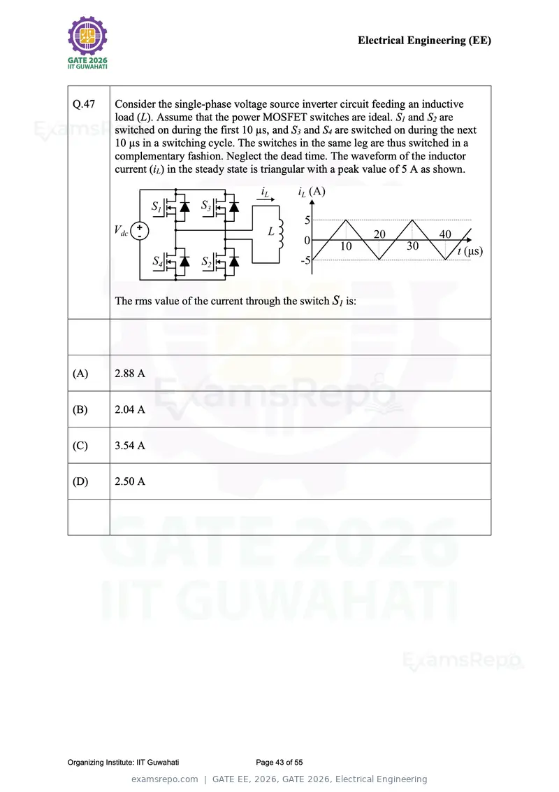
Text of page 43
Electrical Engineering (EE)


 Q.47         Consider the single-phase voltage source inverter circuit feeding an inductive
              load (L). Assume that the power MOSFET switches are ideal. S1 and S2 are
              switched on during the first 10 µs, and S3 and S4 are switched on during the next
              10 µs in a switching cycle. The switches in the same leg are thus switched in a
              complementary fashion. Neglect the dead time. The waveform of the inductor
              current (iL) in the steady state is triangular with a peak value of 5 A as shown.


              The rms value of the current through the switch S1 is:


 (A)          2.88 A


 (B)          2.04 A


 (C)          3.54 A


 (D)          2.50 A


Organizing Institute: IIT Guwahati           Page 43 of 55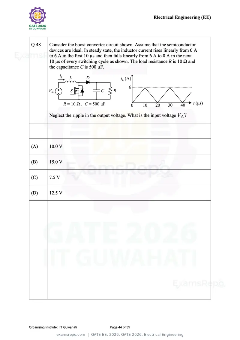
Text of page 44
Electrical Engineering (EE)


 Q.48         Consider the boost converter circuit shown. Assume that the semiconductor
              devices are ideal. In steady state, the inductor current rises linearly from 0 A
              to 6 A in the first 10 µs and then falls linearly from 6 A to 0 A in the next
              10 µs of every switching cycle as shown. The load resistance R is 10 Ω and
              the capacitance C is 500 µF.


              Neglect the ripple in the output voltage. What is the input voltage Vdc?


 (A)          10.0 V


 (B)          15.0 V


 (C)          7.5 V


 (D)          12.5 V


Organizing Institute: IIT Guwahati            Page 44 of 55
Text of page 45
Electrical Engineering (EE)


 Q.49         Which one of the following statements is ALWAYS correct about a collection of
              p column vectors, each having n real-valued entries?


 (A)          If p > n, then the column vectors must be linearly dependent


 (B)          If p > n, then the column vectors must be linearly independent


 (C)          If p = n, then the column vectors must be orthogonal


 (D)          If p < n, then the column vectors must be linearly independent


Organizing Institute: IIT Guwahati         Page 45 of 55
Text of page 46
Electrical Engineering (EE)


 Q.50         Consider the second-order differential equation

                                            d 2 y dy
                                                 +   +y =0
                                            dx 2 dx
              with initial conditions
                                                             dy
                                         y(0) = 1,              |   = 1
                                                             dx x=0
              The solution is given by


 (A)
                                     √3x             √3x
              y(x) = exp(−x/2) (cos (    ) + √3sin (     ))
                                      2               2


  (B)
                                     √3x      1      √3x
              y(x) = exp(−x/2) (cos (    ) +    sin (    ))
                                      2      √3       2


 (C)
                                     √3x      1      √3x
              y(x) = exp(−x/2) (cos (    ) −    sin (    ))
                                      2      √3       2


 (D)
                                     √3x             √3x
              y(x) = exp(−x/2) (cos (    ) − √3sin (     ))
                                      2               2


Organizing Institute: IIT Guwahati           Page 46 of 55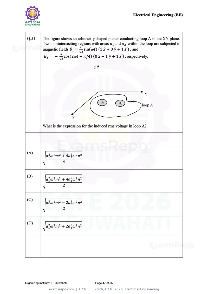
Text of page 47
Electrical Engineering (EE)


 Q.51         The figure shows an arbitrarily shaped planar conducting loop A in the XY plane.
              Two nonintersecting regions with areas a1 and a2 within the loop are subjected to
                              ⃗⃗1 = m sin(ωt) (1 x̂ + 0 ŷ + 1 ẑ ) , and
              magnetic fields B
                                    √2
                        n
               ⃗⃗
              B2 = − cos(2ωt + π/4) (0 x̂ + 1 ŷ + 1 ẑ ) , respectively.
                            √2


              What is the expression for the induced rms voltage in loop A?


 (A)
               a2 ω 2 m2 + 4a22 ω 2 n2
              √ 1
                         4


 (B)
               a2 ω 2 m2 + 4a22 ω 2 n2
              √ 1
                         2


 (C)
               a2 ω 2 m2 − 2a22 ω 2 n2
              √ 1
                         2


 (D)
              √a12 ω 2 m2 + 2a22 ω 2 n2


Organizing Institute: IIT Guwahati          Page 47 of 55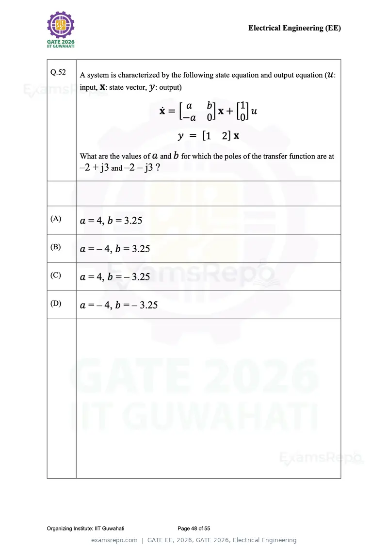
Text of page 48
Electrical Engineering (EE)


 Q.52         A system is characterized by the following state equation and output equation (u :
              input, x: state vector, y: output)

                                               a         b       1
                                        ẋ = [             ]x + [ ]u
                                              −a         0       0
                                              y = [1          2] x
              What are the values of a and b for which the poles of the transfer function are at
              –2 + j3 and –2 – j3 ?


 (A)          a = 4, b = 3.25

 (B)          a = – 4, b = 3.25

 (C)          a = 4, b = – 3.25

 (D)          a = – 4, b = – 3.25


Organizing Institute: IIT Guwahati            Page 48 of 55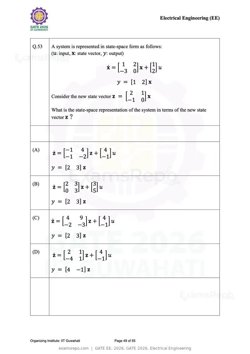
Text of page 49
Electrical Engineering (EE)


 Q.53         A system is represented in state-space form as follows:
              (u: input, x: state vector, y: output)

                                                   1 2        1
                                          ẋ = [        ]x + [ ]u
                                                   −3 0       2
                                                y = [1 2 ] x
                                                       2 1
              Consider the new state vector z = [           ]x
                                                       −1 0
              What is the state-space representation of the system in terms of the new state
              vector z ?


 (A)                 −1          4        4
               ż = [               ]z + [ ]u
                     −1          −2       −1
              y = [2           3] z

 (B)                 2 3       3
               ż = [    ]z + [ ]u
                     0 3       5
              y = [2           3] z

 (C)                 4          9        4
              ż = [               ]z + [ ]u
                    −2          −3       −1
              y = [2           3] z

 (D)                  2          1        4
               ż = [              ]z + [ ]u
                     −4          1       −1
              y = [4           −1] z


Organizing Institute: IIT Guwahati             Page 49 of 55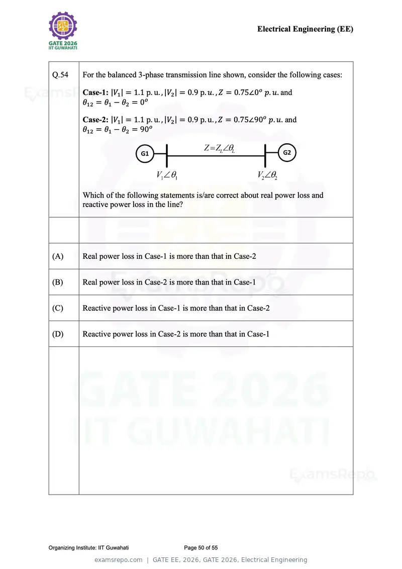
Text of page 50
Electrical Engineering (EE)


 Q.54         For the balanced 3-phase transmission line shown, consider the following cases:

              Case-1: |V1 | = 1.1 p. u. , |V2 | = 0.9 p. u. , Z = 0.75∠0o p. u. and
              θ12 = θ1 − θ2 = 0o

              Case-2: |V1 | = 1.1 p. u. , |V2 | = 0.9 p. u. , Z = 0.75∠90o p. u. and
              θ12 = θ1 − θ2 = 90o


              Which of the following statements is/are correct about real power loss and
              reactive power loss in the line?


 (A)          Real power loss in Case-1 is more than that in Case-2


 (B)          Real power loss in Case-2 is more than that in Case-1


 (C)          Reactive power loss in Case-1 is more than that in Case-2


 (D)          Reactive power loss in Case-2 is more than that in Case-1


Organizing Institute: IIT Guwahati             Page 50 of 55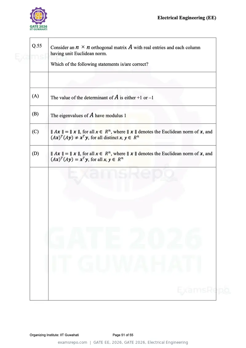
Text of page 51
Electrical Engineering (EE)


 Q.55         Consider an n × n orthogonal matrix A with real entries and each column
              having unit Euclidean norm.

              Which of the following statements is/are correct?


 (A)          The value of the determinant of A is either +1 or –1


 (B)          The eigenvalues of A have modulus 1


 (C)          ∥ Ax ∥ = ∥ x ∥, for all x ∈ R n , where ∥ x ∥ denotes the Euclidean norm of x, and
              (Ax)T (Ay) ≠ xT y, for all distinct x, y ∈ R n


 (D)          ∥ Ax ∥ = ∥ x ∥, for all x ∈ R n , where ∥ x ∥ denotes the Euclidean norm of x, and
              (Ax)T (Ay) = xT y, for all x, y ∈ R n


Organizing Institute: IIT Guwahati           Page 51 of 55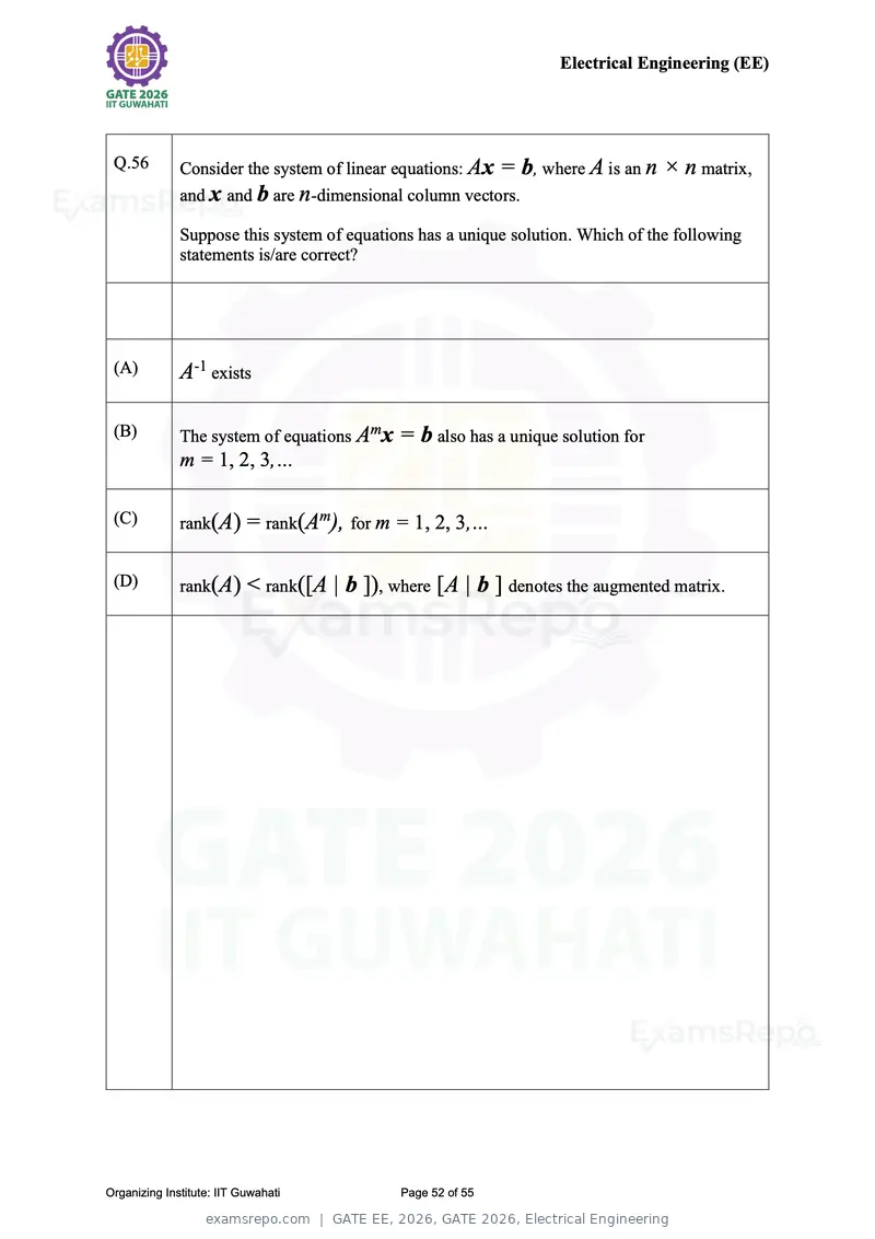
Text of page 52
Electrical Engineering (EE)


 Q.56         Consider the system of linear equations: Ax = b, where A is an n × n matrix,
              and x and b are n-dimensional column vectors.

              Suppose this system of equations has a unique solution. Which of the following
              statements is/are correct?


 (A)          A-1 exists

 (B)          The system of equations Amx = b also has a unique solution for
              m = 1, 2, 3,…

 (C)          rank(A) = rank(Am), for m = 1, 2, 3,…


 (D)          rank(A) < rank([A | b ]), where [A | b ] denotes the augmented matrix.


Organizing Institute: IIT Guwahati          Page 52 of 55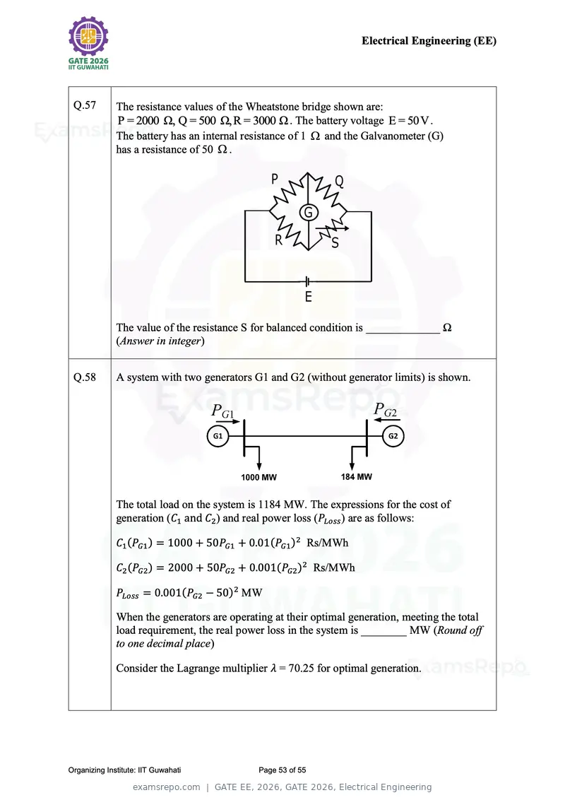
Text of page 53
Electrical Engineering (EE)
Q.57 The resistance values of the Wheatstone bridge shown are:
P = 2000 Ω, Q = 500 Ω,R = 3000 Ω . The battery voltage E = 50V .
The battery has an internal resistance of 1 and the Galvanometer (G)
has a resistance of 50 .
The value of the resistance S for balanced condition is _____________ Ω
(Answer in integer)
Q.58 A system with two generators G1 and G2 (without generator limits) is shown.
The total load on the system is 1184 MW. The expressions for the cost of
generation (C1 and C2 ) and real power loss (PLoss ) are as follows:
C1 (PG1 ) = 1000 + 50PG1 + 0.01(PG1 )2 Rs/MWh
C2 (PG2 ) = 2000 + 50PG2 + 0.001(PG2 )2 Rs/MWh
PLoss = 0.001(PG2 − 50)2 MW
When the generators are operating at their optimal generation, meeting the total
load requirement, the real power loss in the system is ________ MW (Round off
to one decimal place)
Consider the Lagrange multiplier λ = 70.25 for optimal generation.
Organizing Institute: IIT Guwahati Page 53 of 55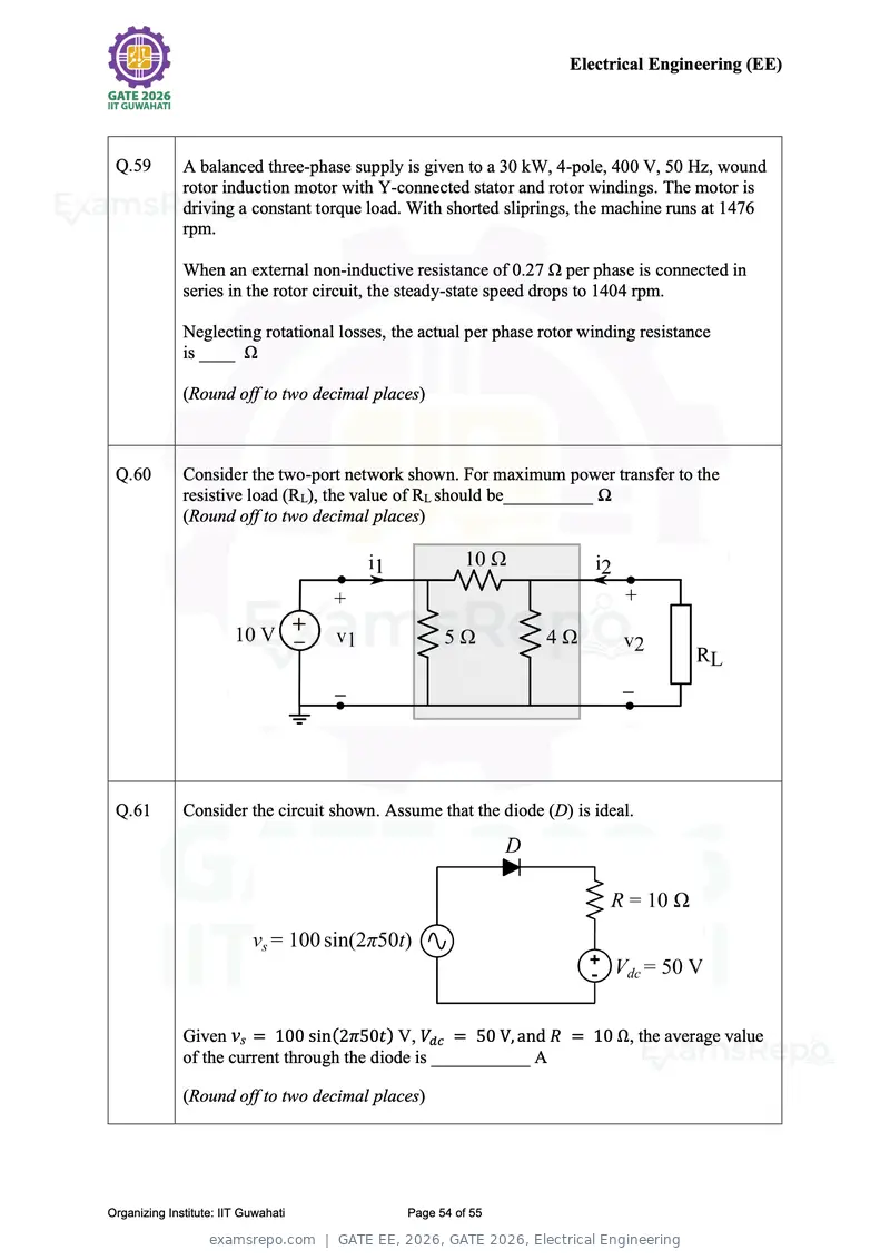
Text of page 54
Electrical Engineering (EE)


 Q.59         A balanced three-phase supply is given to a 30 kW, 4-pole, 400 V, 50 Hz, wound
              rotor induction motor with Y-connected stator and rotor windings. The motor is
              driving a constant torque load. With shorted sliprings, the machine runs at 1476
              rpm.

              When an external non-inductive resistance of 0.27 Ω per phase is connected in
              series in the rotor circuit, the steady-state speed drops to 1404 rpm.

              Neglecting rotational losses, the actual per phase rotor winding resistance
              is ____ Ω

              (Round off to two decimal places)


 Q.60         Consider the two-port network shown. For maximum power transfer to the
              resistive load (RL), the value of RL should be__________ Ω
              (Round off to two decimal places)


 Q.61         Consider the circuit shown. Assume that the diode (D) is ideal.


              Given vs = 100 sin(2π50t) V, Vdc = 50 V, and R = 10 Ω, the average value
              of the current through the diode is ___________ A

              (Round off to two decimal places)


Organizing Institute: IIT Guwahati           Page 54 of 55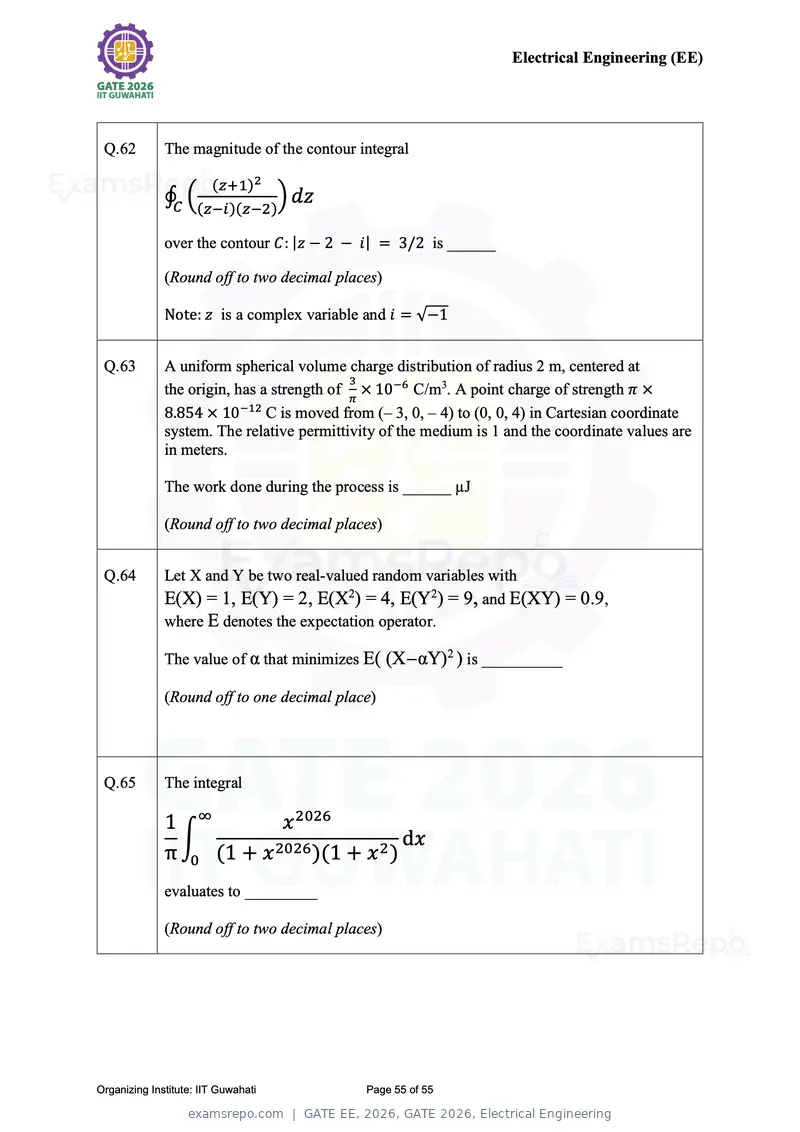
Text of page 55
Electrical Engineering (EE)


 Q.62         The magnitude of the contour integral

                        (z+1)2
              ∮C ((z−i)(z−2)) dz

              over the contour C: |z − 2 − i| = 3/2 is ______

              (Round off to two decimal places)

              Note: z is a complex variable and i = √−1


 Q.63         A uniform spherical volume charge distribution of radius 2 m, centered at
                                            3
              the origin, has a strength of π × 10−6 C/m3. A point charge of strength π ×
              8.854 × 10⁻¹² C is moved from (– 3, 0, – 4) to (0, 0, 4) in Cartesian coordinate
              system. The relative permittivity of the medium is 1 and the coordinate values are
              in meters.

              The work done during the process is ______ µJ

              (Round off to two decimal places)


 Q.64         Let X and Y be two real-valued random variables with
              E(X) = 1, E(Y) = 2, E(X2) = 4, E(Y2) = 9, and E(XY) = 0.9,
              where E denotes the expectation operator.

              The value of α that minimizes E( (X−αY)2 ) is __________

              (Round off to one decimal place)


 Q.65         The integral

              1 ∞         x 2026
               ∫                          dx
              π 0 (1 + x 2026 )(1 + x 2 )
              evaluates to _________

              (Round off to two decimal places)


Organizing Institute: IIT Guwahati           Page 55 of 55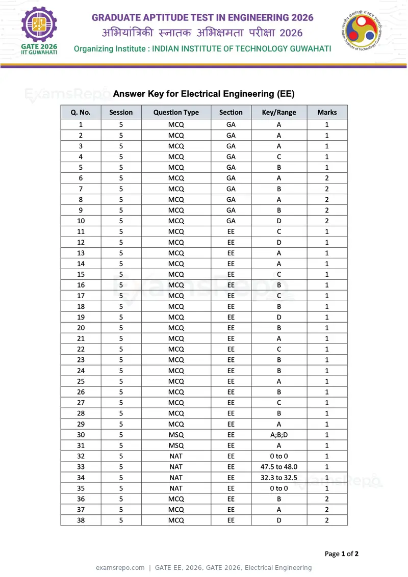
Text of page 1
Answer Key for Electrical Engineering (EE)

Q. No.   Session   Question Type   Section   Key/Range      Marks
 1         5           MCQ           GA           A           1
 2         5           MCQ           GA           A           1
 3         5           MCQ           GA           A           1
 4         5           MCQ           GA           C           1
 5         5           MCQ           GA           B           1
 6         5           MCQ           GA           A           2
 7         5           MCQ           GA           B           2
 8         5           MCQ           GA           A           2
 9         5           MCQ           GA           B           2
 10        5           MCQ           GA           D           2
 11        5           MCQ           EE           C           1
 12        5           MCQ           EE           D           1
 13        5           MCQ           EE           A           1
 14        5           MCQ           EE           A           1
 15        5           MCQ           EE           C           1
 16        5           MCQ           EE           B           1
 17        5           MCQ           EE           C           1
 18        5           MCQ           EE           B           1
 19        5           MCQ           EE           D           1
 20        5           MCQ           EE           B           1
 21        5           MCQ           EE           A           1
 22        5           MCQ           EE           C           1
 23        5           MCQ           EE           B           1
 24        5           MCQ           EE           B           1
 25        5           MCQ           EE           A           1
 26        5           MCQ           EE           B           1
 27        5           MCQ           EE           C           1
 28        5           MCQ           EE           B           1
 29        5           MCQ           EE           A           1
 30        5           MSQ           EE         A;B;D         1
 31        5           MSQ           EE           A           1
 32        5           NAT           EE         0 to 0        1
 33        5           NAT           EE      47.5 to 48.0     1
 34        5           NAT           EE      32.3 to 32.5     1
 35        5           NAT           EE         0 to 0        1
 36        5           MCQ           EE           B           2
 37        5           MCQ           EE           A           2
 38        5           MCQ           EE           D           2


                                                             Page 1 of 2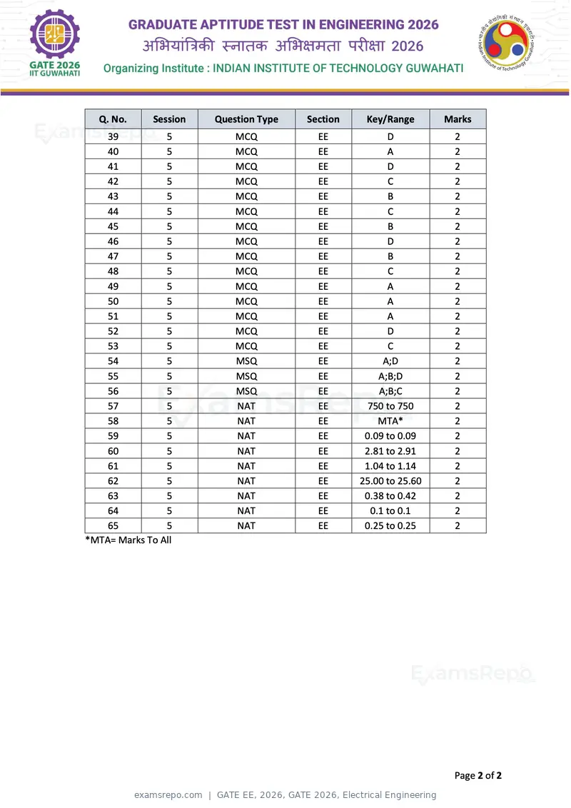
Text of page 2
Q. No.      Session   Question Type   Section    Key/Range       Marks
    39          5           MCQ           EE            D            2
    40          5           MCQ           EE            A            2
    41          5           MCQ           EE            D            2
    42          5           MCQ           EE            C            2
    43          5           MCQ           EE            B            2
    44          5           MCQ           EE            C            2
    45          5           MCQ           EE            B            2
    46          5           MCQ           EE            D            2
    47          5           MCQ           EE            B            2
    48          5           MCQ           EE            C            2
    49          5           MCQ           EE            A            2
    50          5           MCQ           EE            A            2
    51          5           MCQ           EE            A            2
    52          5           MCQ           EE            D            2
    53          5           MCQ           EE            C            2
    54          5           MSQ           EE           A;D           2
    55          5           MSQ           EE          A;B;D          2
    56          5           MSQ           EE          A;B;C          2
    57          5           NAT           EE       750 to 750        2
    58          5           NAT           EE          MTA*           2
    59          5           NAT           EE       0.09 to 0.09      2
    60          5           NAT           EE       2.81 to 2.91      2
    61          5           NAT           EE       1.04 to 1.14      2
    62          5           NAT           EE      25.00 to 25.60     2
    63          5           NAT           EE       0.38 to 0.42      2
    64          5           NAT           EE        0.1 to 0.1       2
    65          5           NAT           EE       0.25 to 0.25      2
*MTA= Marks To All


                                                                    Page 2 of 2
Page 1 of 55
Source: GATE. Question paper published by GATE.