
GATE IN 2025: Instrumentation Engineering
Text of page 1
Instrumentation Engineering (IN)


General Aptitude
Q.1 – Q.5 Carry ONE mark Each

 Q.1      Despite his initial hesitation, Rehman’s _________ to contribute to the success of
          the project never wavered.

          Select the most appropriate option to complete the above sentence.


 (A)      ambivalence


 (B)      satisfaction


 (C)      resolve


 (D)      revolve


Organizing Institute: IIT Roorkee         Page 1 of 65
Text of page 2
Instrumentation Engineering (IN)


 Q.2      Bird : Nest :: Bee : _______

          Select the correct option to complete the analogy.


 (A)      Kennel


 (B)      Hammock


 (C)      Hive


 (D)      Lair


Organizing Institute: IIT Roorkee          Page 2 of 65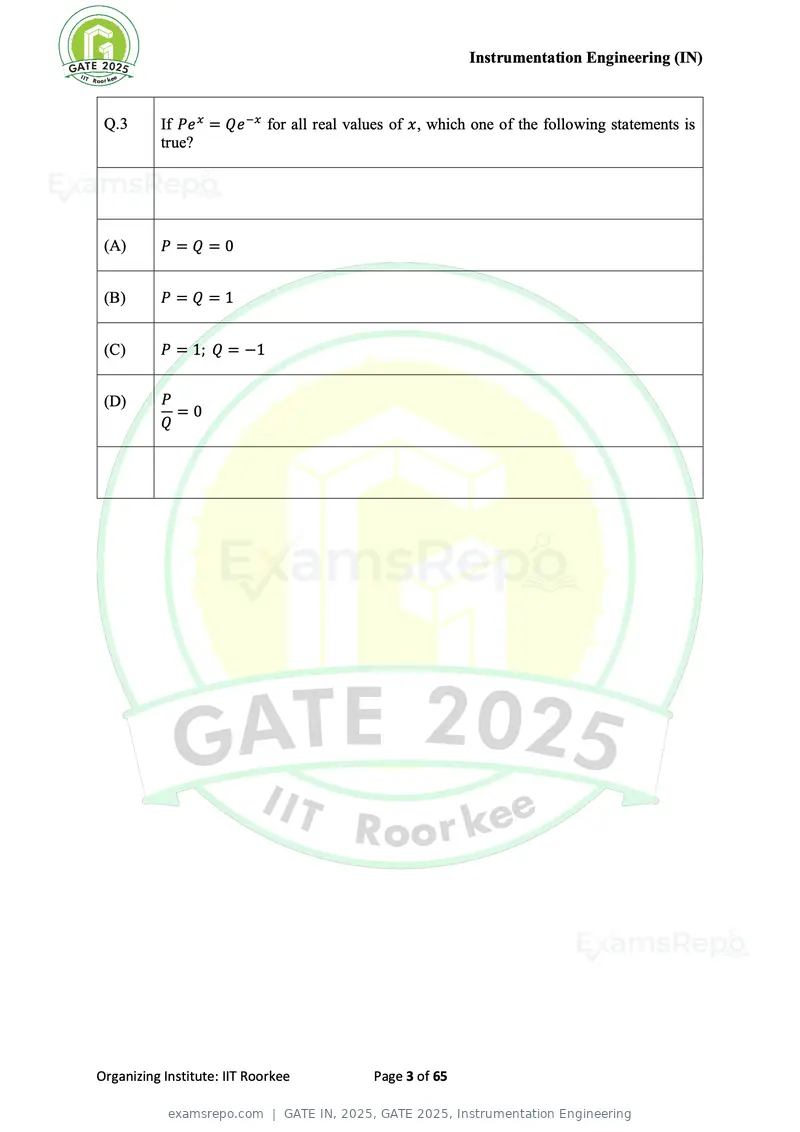
Text of page 3
Instrumentation Engineering (IN)


 Q.3      If Pe x = Qe −x for all real values of x, which one of the following statements is
          true?


 (A)      P=Q=0


 (B)      P=Q=1


 (C)      P = 1; Q = −1


 (D)      P
            =0
          Q


Organizing Institute: IIT Roorkee         Page 3 of 65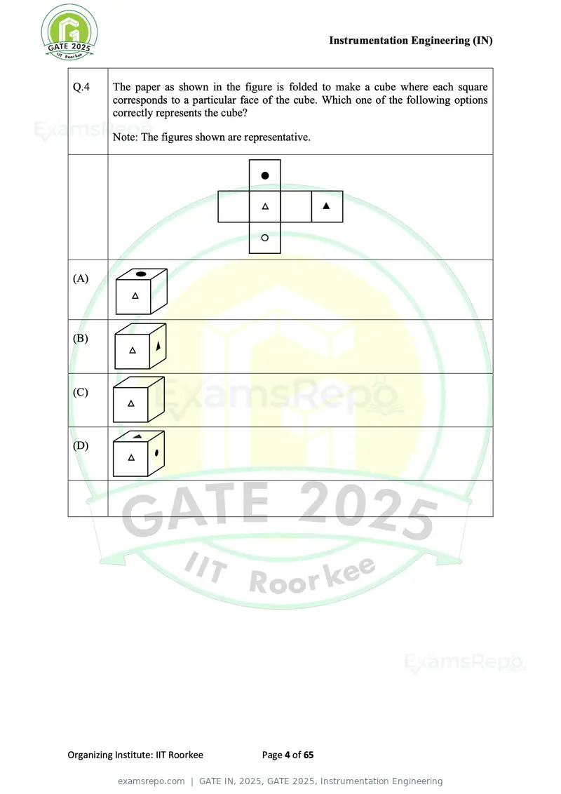
Text of page 4
Instrumentation Engineering (IN)


 Q.4      The paper as shown in the figure is folded to make a cube where each square
          corresponds to a particular face of the cube. Which one of the following options
          correctly represents the cube?

          Note: The figures shown are representative.


 (A)


 (B)


 (C)


 (D)


Organizing Institute: IIT Roorkee         Page 4 of 65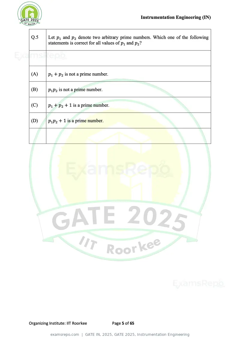
Text of page 5
Instrumentation Engineering (IN)


 Q.5      Let p1 and p2 denote two arbitrary prime numbers. Which one of the following
          statements is correct for all values of p1 and p2 ?


 (A)      p1 + p2 is not a prime number.


 (B)      p1 p2 is not a prime number.


 (C)      p1 + p2 + 1 is a prime number.


 (D)      p1 p2 + 1 is a prime number.


Organizing Institute: IIT Roorkee          Page 5 of 65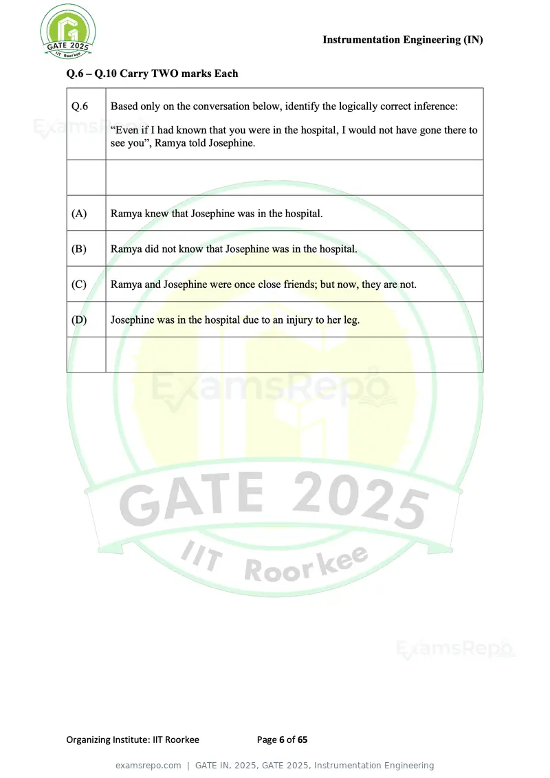
Text of page 6
Instrumentation Engineering (IN)


Q.6 – Q.10 Carry TWO marks Each

 Q.6      Based only on the conversation below, identify the logically correct inference:

          “Even if I had known that you were in the hospital, I would not have gone there to
          see you”, Ramya told Josephine.


 (A)      Ramya knew that Josephine was in the hospital.


 (B)      Ramya did not know that Josephine was in the hospital.


 (C)      Ramya and Josephine were once close friends; but now, they are not.


 (D)      Josephine was in the hospital due to an injury to her leg.


Organizing Institute: IIT Roorkee           Page 6 of 65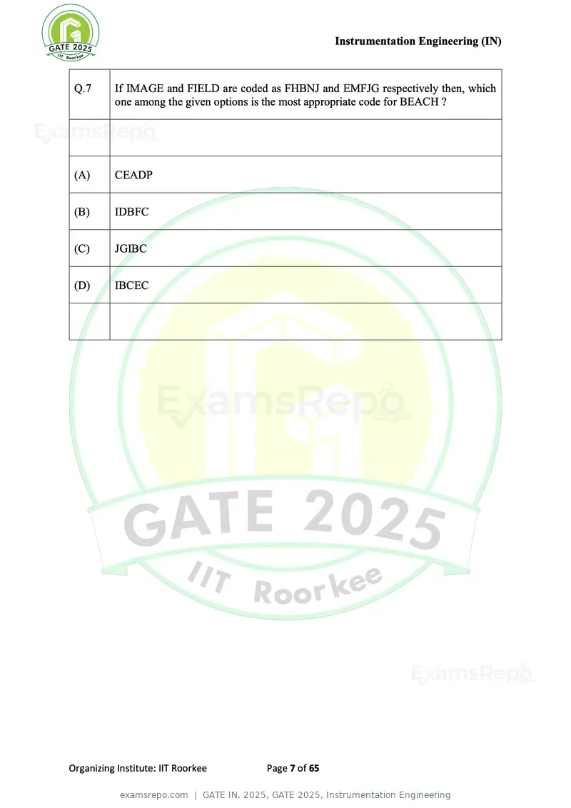
Text of page 7
Instrumentation Engineering (IN)


 Q.7      If IMAGE and FIELD are coded as FHBNJ and EMFJG respectively then, which
          one among the given options is the most appropriate code for BEACH ?


 (A)      CEADP


 (B)      IDBFC


 (C)      JGIBC


 (D)      IBCEC


Organizing Institute: IIT Roorkee     Page 7 of 65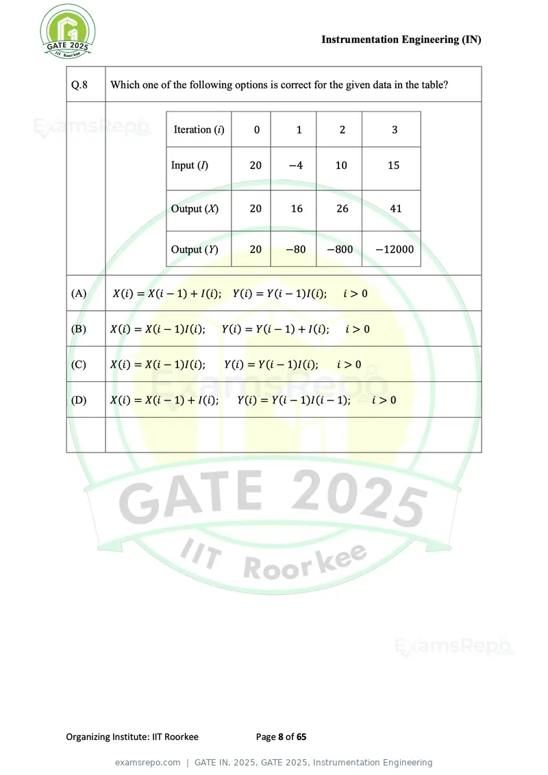
Text of page 8
Instrumentation Engineering (IN)


 Q.8      Which one of the following options is correct for the given data in the table?


                          Iteration (i)       0        1         2          3


                          Input (I)          20      −4          10        15


                          Output (X)         20       16         26        41


                          Output (Y)         20      −80       −800     −12000


 (A)       X(i) = X(i − 1) + I(i);        Y(i) = Y(i − 1)I(i);    i>0


 (B)      X(i) = X(i − 1)I(i);         Y(i) = Y(i − 1) + I(i);    i>0


 (C)      X(i) = X(i − 1)I(i);         Y(i) = Y(i − 1)I(i);      i>0


 (D)      X(i) = X(i − 1) + I(i);         Y(i) = Y(i − 1)I(i − 1);      i>0


Organizing Institute: IIT Roorkee             Page 8 of 65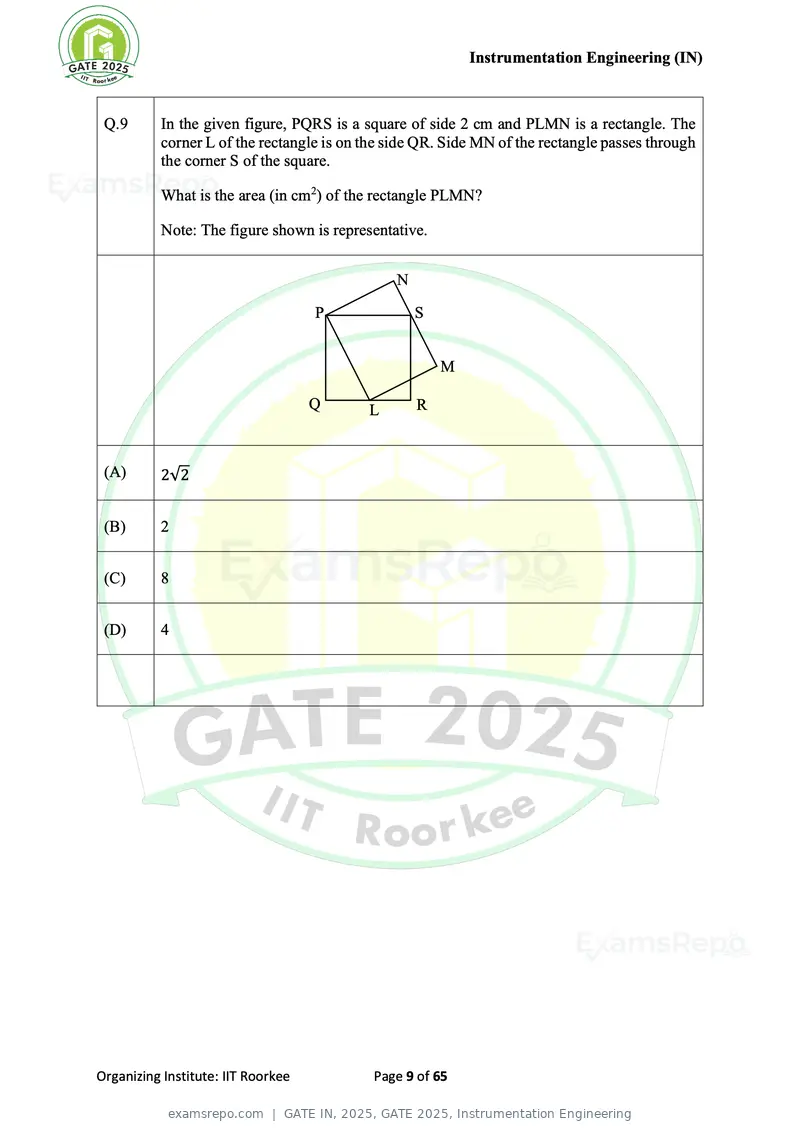
Text of page 9
Instrumentation Engineering (IN)


 Q.9      In the given figure, PQRS is a square of side 2 cm and PLMN is a rectangle. The
          corner L of the rectangle is on the side QR. Side MN of the rectangle passes through
          the corner S of the square.

          What is the area (in cm2) of the rectangle PLMN?

          Note: The figure shown is representative.


                                               N

                                    P              S


                                                       M

                                    Q     L        R


 (A)      2√2


 (B)      2


 (C)      8


 (D)      4


Organizing Institute: IIT Roorkee          Page 9 of 65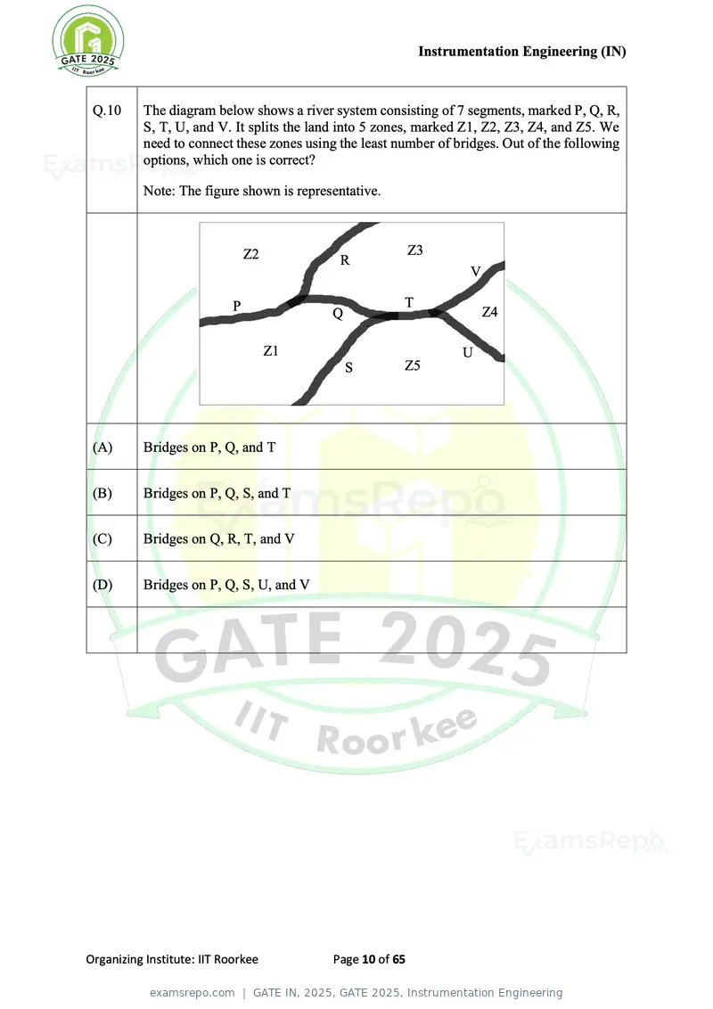
Text of page 10
Instrumentation Engineering (IN)


 Q.10     The diagram below shows a river system consisting of 7 segments, marked P, Q, R,
          S, T, U, and V. It splits the land into 5 zones, marked Z1, Z2, Z3, Z4, and Z5. We
          need to connect these zones using the least number of bridges. Out of the following
          options, which one is correct?

          Note: The figure shown is representative.


                                Z2                         Z3
                                            R
                                                                    V

                            P                          T
                                          Q                             Z4

                                     Z1                           U
                                              S        Z5


 (A)      Bridges on P, Q, and T


 (B)      Bridges on P, Q, S, and T


 (C)      Bridges on Q, R, T, and V


 (D)      Bridges on P, Q, S, U, and V


Organizing Institute: IIT Roorkee          Page 10 of 65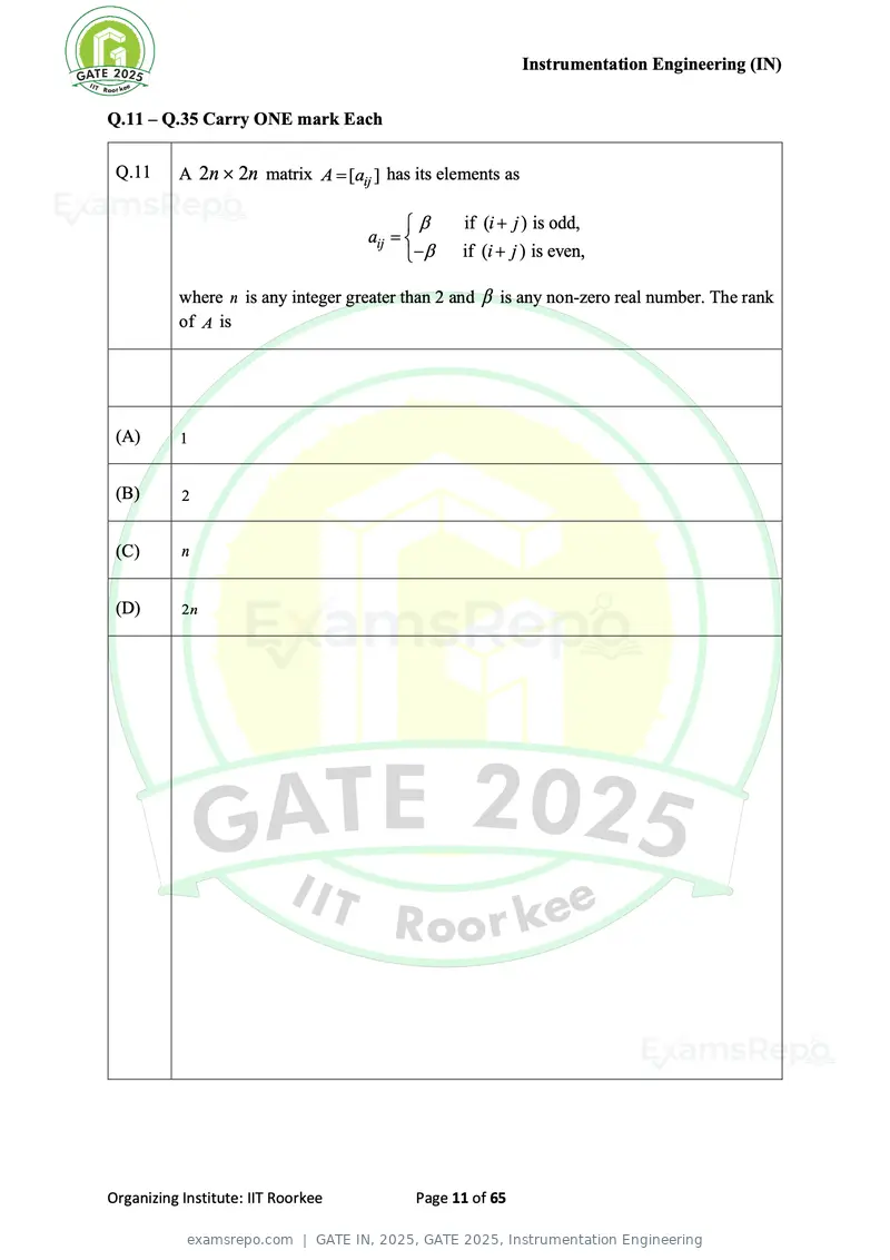
Text of page 11
Instrumentation Engineering (IN)
Q.11 – Q.35 Carry ONE mark Each
Q.11 A 2n 2n matrix A = [aij ] has its elements as
if (i + j ) is odd,
aij =
− if (i + j ) is even,
where n is any integer greater than 2 and is any non-zero real number. The rank
of A is
(A) 1
(B) 2
(C) n
(D) 2n
Organizing Institute: IIT Roorkee Page 11 of 65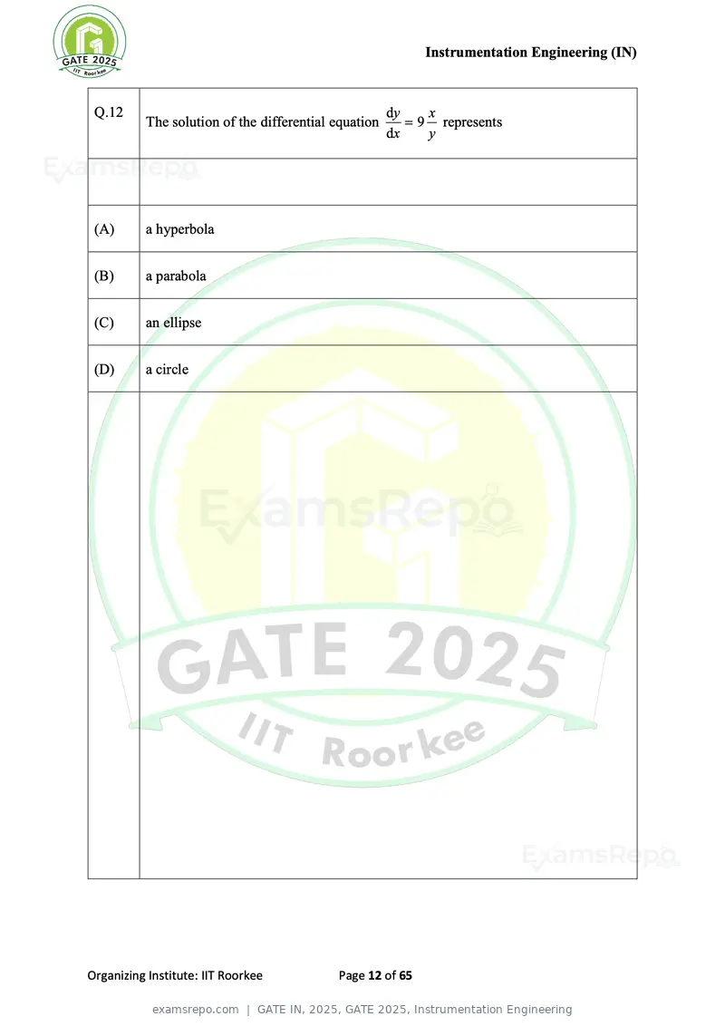
Text of page 12
Instrumentation Engineering (IN)


 Q.12                                                 dy    x
          The solution of the differential equation      = 9 represents
                                                      dx    y


 (A)      a hyperbola


 (B)      a parabola


 (C)      an ellipse


 (D)      a circle


Organizing Institute: IIT Roorkee          Page 12 of 65
Text of page 13
Instrumentation Engineering (IN)


 Q.13     The working of the hand-held metal detector most widely used by security
          personnel for human frisking is based on the principle of


 (A)      change in reluctance of an iron core in presence of a metallic object


 (B)      change in conductance of an iron core in presence of a metallic object


 (C)      electric field induced by a metallic object


 (D)      eddy current generation in a metallic object


Organizing Institute: IIT Roorkee           Page 13 of 65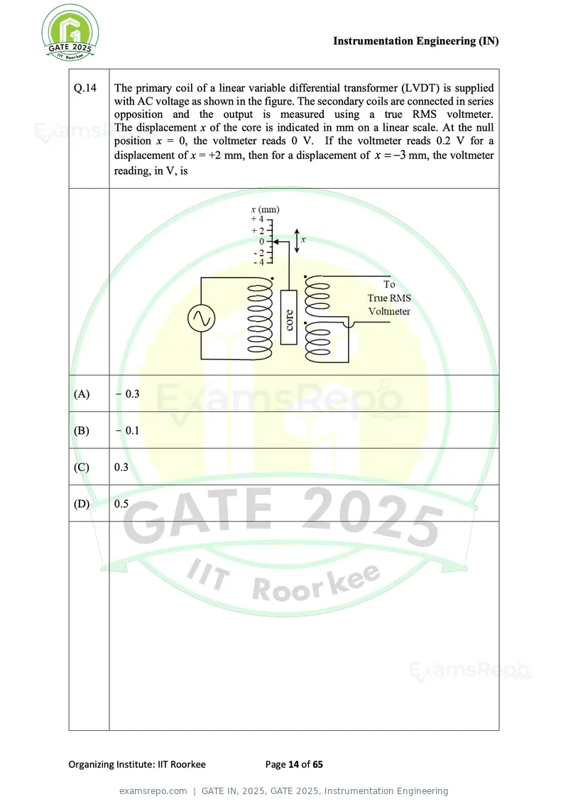
Text of page 14
Instrumentation Engineering (IN)


 Q.14     The primary coil of a linear variable differential transformer (LVDT) is supplied
          with AC voltage as shown in the figure. The secondary coils are connected in series
          opposition and the output is measured using a true RMS voltmeter.
          The displacement x of the core is indicated in mm on a linear scale. At the null
          position x = 0, the voltmeter reads 0 V. If the voltmeter reads 0.2 V for a
          displacement of x = +2 mm, then for a displacement of x = −3 mm, the voltmeter
          reading, in V, is


 (A)       − 0.3


 (B)       − 0.1


 (C)      0.3


 (D)      0.5


Organizing Institute: IIT Roorkee          Page 14 of 65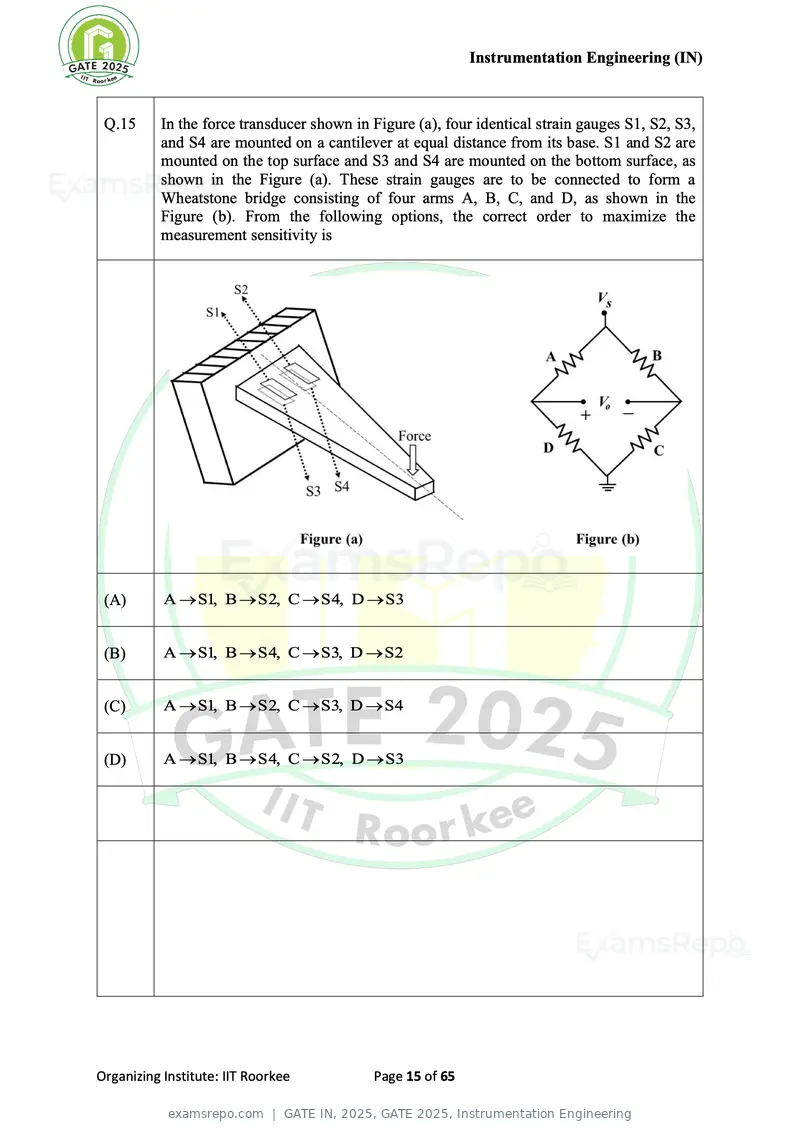
Text of page 15
Instrumentation Engineering (IN)


 Q.15     In the force transducer shown in Figure (a), four identical strain gauges S1, S2, S3,
          and S4 are mounted on a cantilever at equal distance from its base. S1 and S2 are
          mounted on the top surface and S3 and S4 are mounted on the bottom surface, as
          shown in the Figure (a). These strain gauges are to be connected to form a
          Wheatstone bridge consisting of four arms A, B, C, and D, as shown in the
          Figure (b). From the following options, the correct order to maximize the
          measurement sensitivity is


 (A)       A → S1, B → S2, C → S4, D → S3


 (B)       A → S1, B → S4, C → S3, D → S2


 (C)       A → S1, B → S2, C → S3, D → S4


 (D)       A → S1, B → S4, C → S2, D → S3


Organizing Institute: IIT Roorkee          Page 15 of 65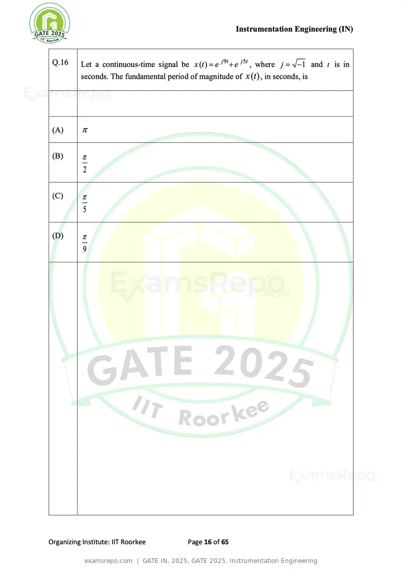
Text of page 16
Instrumentation Engineering (IN)
Q.16 Let a continuous-time signal be x (t ) = e j 9t + e j 5t , where j = −1 and t is in
seconds. The fundamental period of magnitude of x (t ) , in seconds, is
(A)
(B)
2
(C)
5
(D)
9
Organizing Institute: IIT Roorkee Page 16 of 65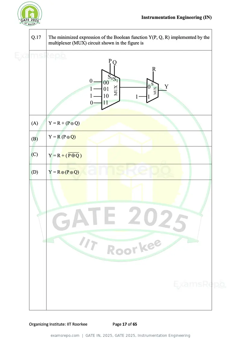
Text of page 17
Instrumentation Engineering (IN)
Q.17 The minimized expression of the Boolean function Y(P, Q, R) implemented by the
multiplexer (MUX) circuit shown in the figure is
(A) Y = R + (P Q)
(B) Y = R (P Q)
(C) Y = R + (PQ )
(D) Y = R (P Q)
Organizing Institute: IIT Roorkee Page 17 of 65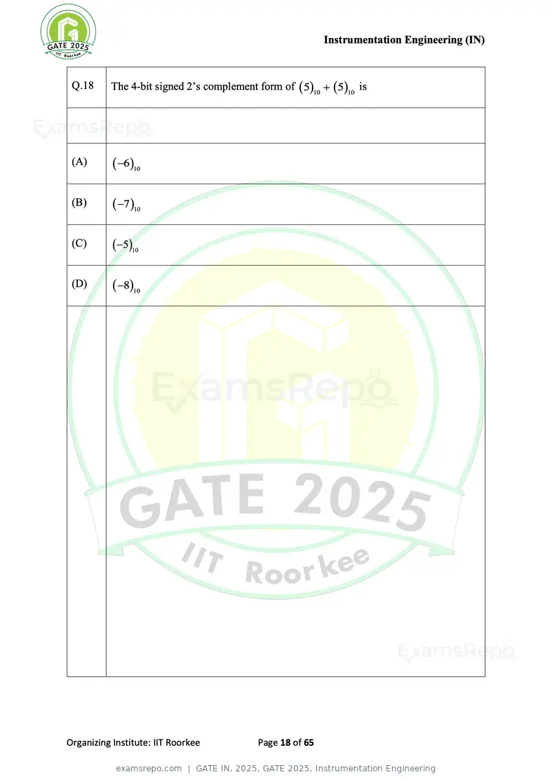
Text of page 18
Instrumentation Engineering (IN)


 Q.18     The 4-bit signed 2’s complement form of ( 5)10 + ( 5)10 is


 (A)       ( −6)10

 (B)       ( −7 )10

 (C)       ( −5)10

 (D)       ( −8)10


Organizing Institute: IIT Roorkee          Page 18 of 65
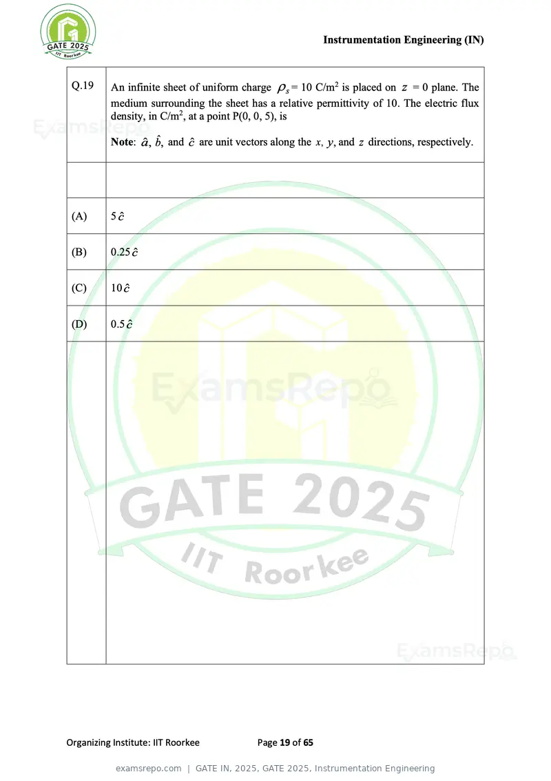
Text of page 19
Instrumentation Engineering (IN)
Q.19 An infinite sheet of uniform charge s = 10 C/m2 is placed on z = 0 plane. The
medium surrounding the sheet has a relative permittivity of 10. The electric flux
density, in C/m2, at a point P(0, 0, 5), is
Note: â , bˆ, and ĉ are unit vectors along the x , y, and z directions, respectively.
(A) 5 ĉ
(B) 0.25 ĉ
(C) 10 ĉ
(D) 0.5 ĉ
Organizing Institute: IIT Roorkee Page 19 of 65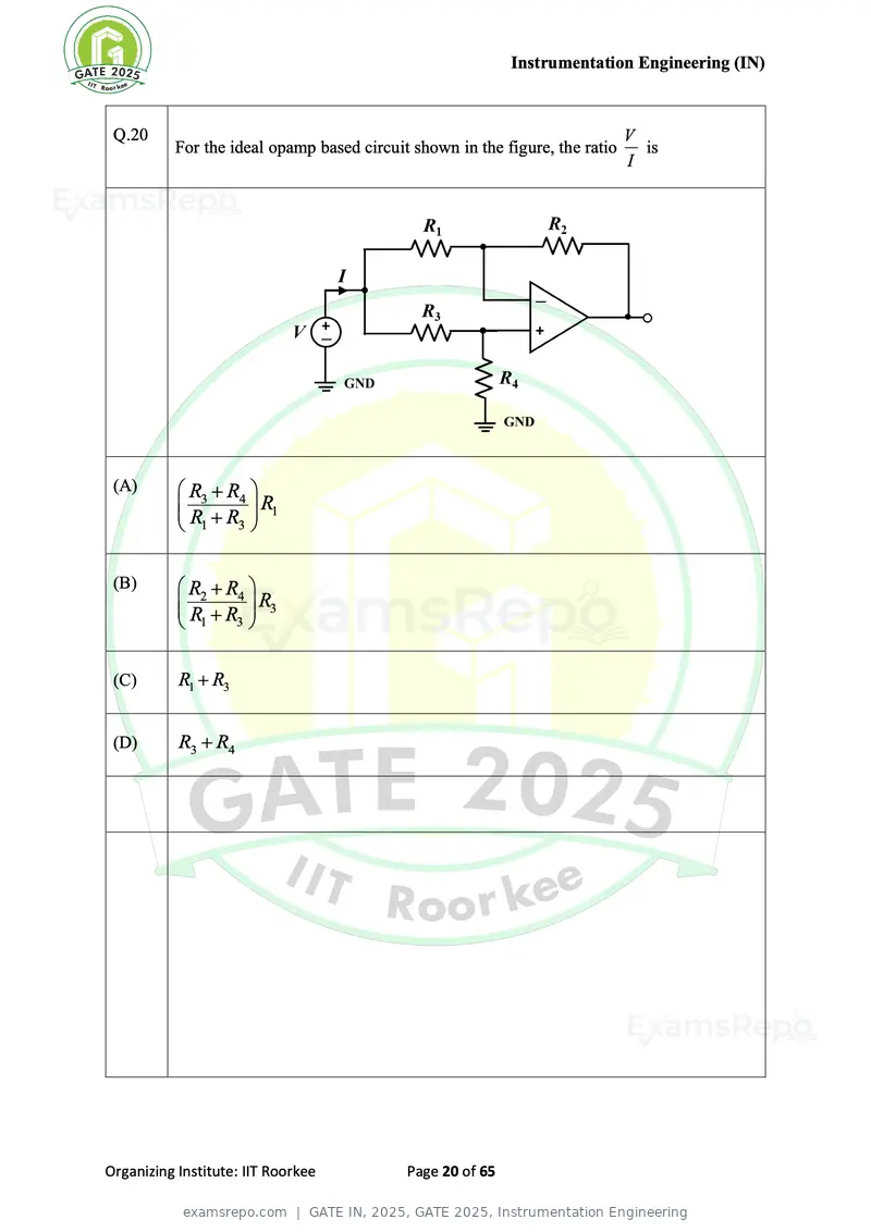
Text of page 20
Instrumentation Engineering (IN)
Q.20 V
For the ideal opamp based circuit shown in the figure, the ratio is
I
(A) R3 + R4
R
R +R 1
1 3
(B) R2 + R4
R
R +R 3
1 3
(C) R1 + R3
(D) R3 + R4
Organizing Institute: IIT Roorkee Page 20 of 65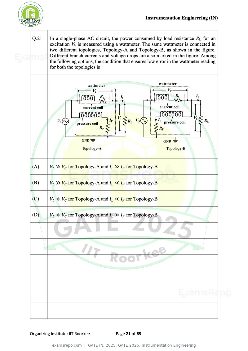
Text of page 21
Instrumentation Engineering (IN)


 Q.21     In a single-phase AC circuit, the power consumed by load resistance RL for an
          excitation VS is measured using a wattmeter. The same wattmeter is connected in
          two different topologies, Topology-A and Topology-B, as shown in the figure.
          Different branch currents and voltage drops are also marked in the figure. Among
          the following options, the condition that ensures low error in the wattmeter reading
          for both the topologies is


 (A)      VL ≫ VC for Topology-A and IL ≫ IP for Topology-B


 (B)      VL ≫ VC for Topology-A and IL ≪ IP for Topology-B


 (C)      VL ≪ VC for Topology-A and IL ≪ IP for Topology-B


 (D)      VL ≪ VC for Topology-A and IL ≫ IP for Topology-B


Organizing Institute: IIT Roorkee          Page 21 of 65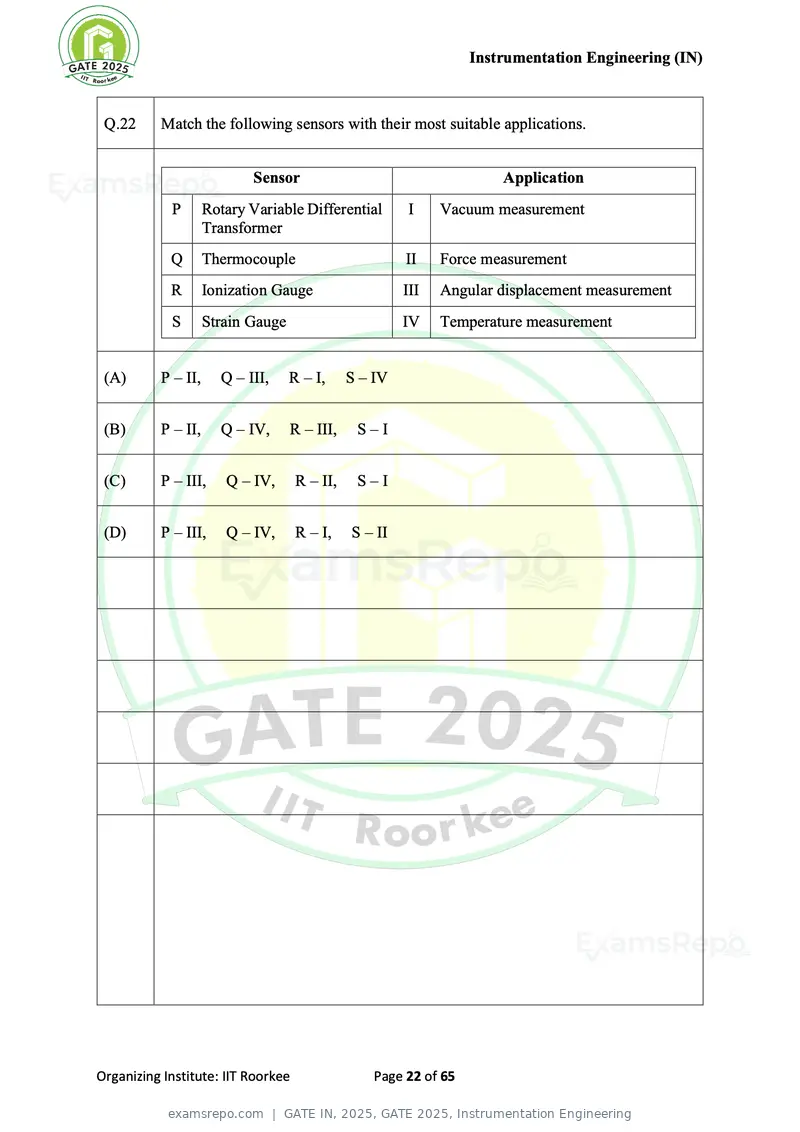
Text of page 22
Instrumentation Engineering (IN)


 Q.22     Match the following sensors with their most suitable applications.


                            Sensor                                    Application
            P       Rotary Variable Differential       I     Vacuum measurement
                    Transformer
            Q       Thermocouple                       II    Force measurement
            R       Ionization Gauge                   III   Angular displacement measurement
            S       Strain Gauge                       IV    Temperature measurement


 (A)      P – II,     Q – III,     R – I,     S – IV


 (B)      P – II,     Q – IV,      R – III,    S–I


 (C)      P – III,     Q – IV,      R – II,    S–I


 (D)      P – III,     Q – IV,      R – I,    S – II


Organizing Institute: IIT Roorkee                 Page 22 of 65
Text of page 23
Instrumentation Engineering (IN)
Q.23 A 3 1 2 digit digital voltmeter has a specified accuracy of (0.5% + 1) . If it is used
to measure 10 V DC voltage, the error in the measurement would be
Note: Accuracy of the digital voltmeter is expressed as ( % of reading + digit).
(A) 0.4 %
(B) 1.5 %
(C) 0.6 %
(D) 1%
Organizing Institute: IIT Roorkee Page 23 of 65
Text of page 24
Instrumentation Engineering (IN)


 Q.24     The circuit shown in Figure (a) can be represented using its equivalent T-model as
          shown in Figure (b). The values of the inductances L1 , L2 , and L3 in the equivalent
          T-model are


 (A)       L1 = 7 H, L2 = 6 H, L3 = − 4 H


 (B)       L1 = −1 H, L2 = − 2 H, L3 = 4 H


 (C)       L1 = 3 H, L2 = 2 H, L3 = 9 H


 (D)       L1 = 1 H, L2 = − 2 H, L3 = − 4 H


Organizing Institute: IIT Roorkee           Page 24 of 65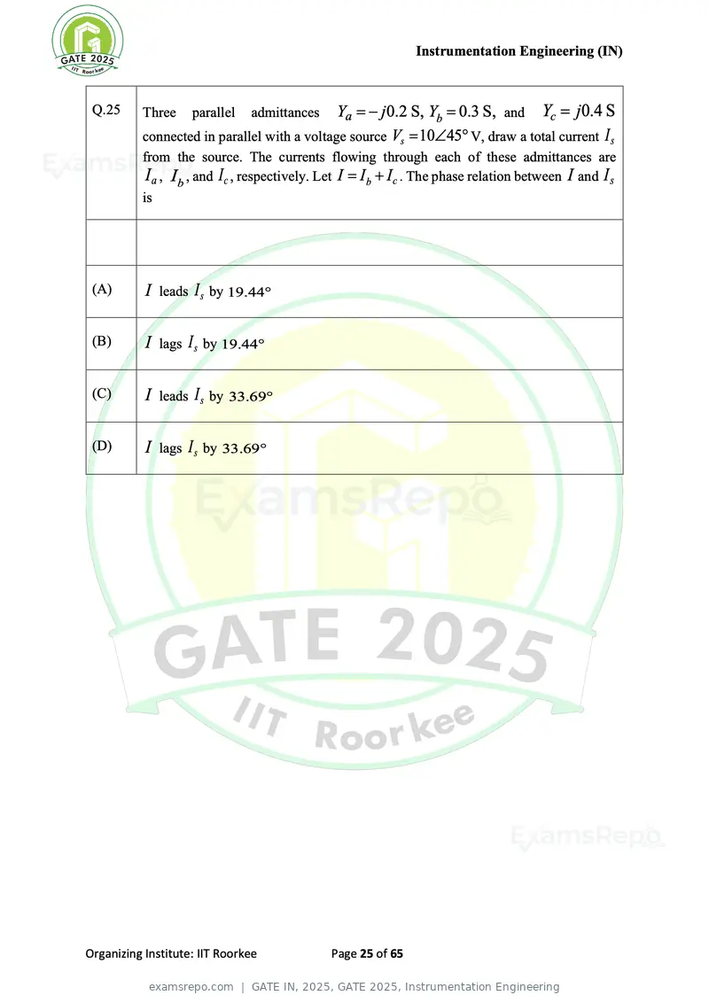
Text of page 25
Instrumentation Engineering (IN)
Q.25 Three parallel admittances Ya = − j 0.2 S, Yb = 0.3 S, and Yc = j 0.4 S
connected in parallel with a voltage source Vs = 1045 V, draw a total current I s
from the source. The currents flowing through each of these admittances are
I a , Ib , and I c , respectively. Let I = Ib + I c . The phase relation between I and I s
is
(A) I leads I s by 19.44
(B) I lags I s by 19.44
(C) I leads I s by 33.69
(D) I lags I s by 33.69
Organizing Institute: IIT Roorkee Page 25 of 65
Text of page 26
Instrumentation Engineering (IN)


 Q.26       An oscilloscope has an input resistance of 1 MΩ . A 10X passive attenuating probe
            is connected to it to increase the input voltage range as well as the effective input
            resistance. The effective input resistance, in MΩ, seen into the probe tip is


 (A)        0.9


 (B)        9.1


 (C)        10


 (D)        11


Organizing Institute: IIT Roorkee            Page 26 of 65
Text of page 27
Instrumentation Engineering (IN)


 Q.27                                                     2s − 1
            For the transfer function G ( s) = 1 +                      , the number of zeros lying
                                                     s + 5s 2 + 3s + 22
                                                       3

            in the left half of the s-plane is


 (A)        0


 (B)        1


 (C)        2


 (D)        3


Organizing Institute: IIT Roorkee                Page 27 of 65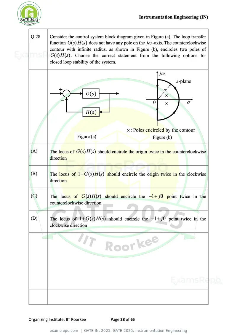
Text of page 28
Instrumentation Engineering (IN)
Q.28 Consider the control system block diagram given in Figure (a). The loop transfer
function G(s) H (s) does not have any pole on the j -axis. The counterclockwise
contour with infinite radius, as shown in Figure (b), encircles two poles of
G(s) H (s) . Choose the correct statement from the following options for
closed loop stability of the system.
Figure (a) Figure (b)
(A) The locus of G (s) H (s) should encircle the origin twice in the counterclockwise
direction
(B) The locus of 1 + G (s) H (s) should encircle the origin twice in the clockwise
direction
(C) The locus of G (s) H (s) should encircle the −1 + j 0 point twice in the
counterclockwise direction
(D) The locus of 1 + G (s) H (s) should encircle the −1 + j 0 point twice in the
clockwise direction
Organizing Institute: IIT Roorkee Page 28 of 65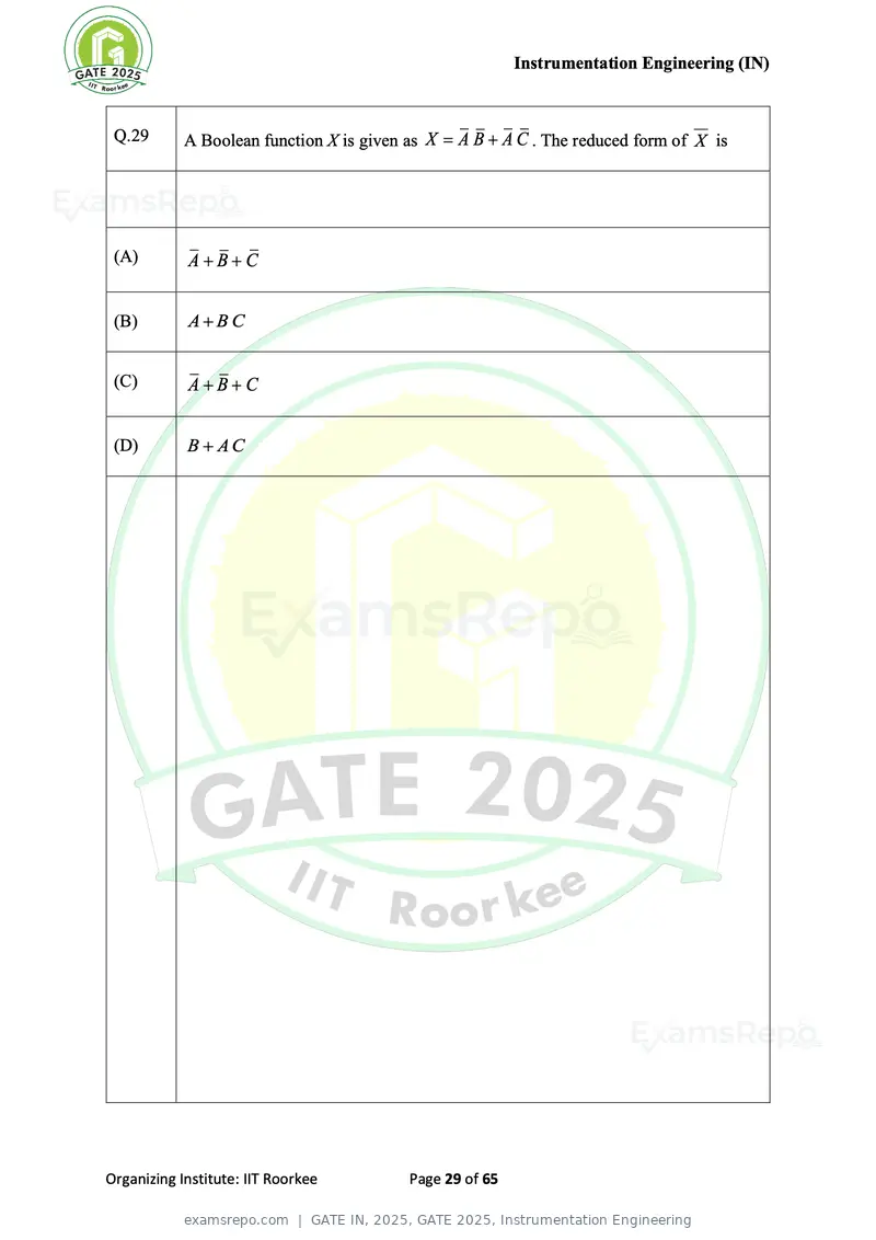
Text of page 29
Instrumentation Engineering (IN)


 Q.29       A Boolean function X is given as X = A B + A C . The reduced form of X is


 (A)        A+B+C


 (B)        A+BC


 (C)        A+B+C


 (D)        B + AC


Organizing Institute: IIT Roorkee         Page 29 of 65
Text of page 30
Instrumentation Engineering (IN)
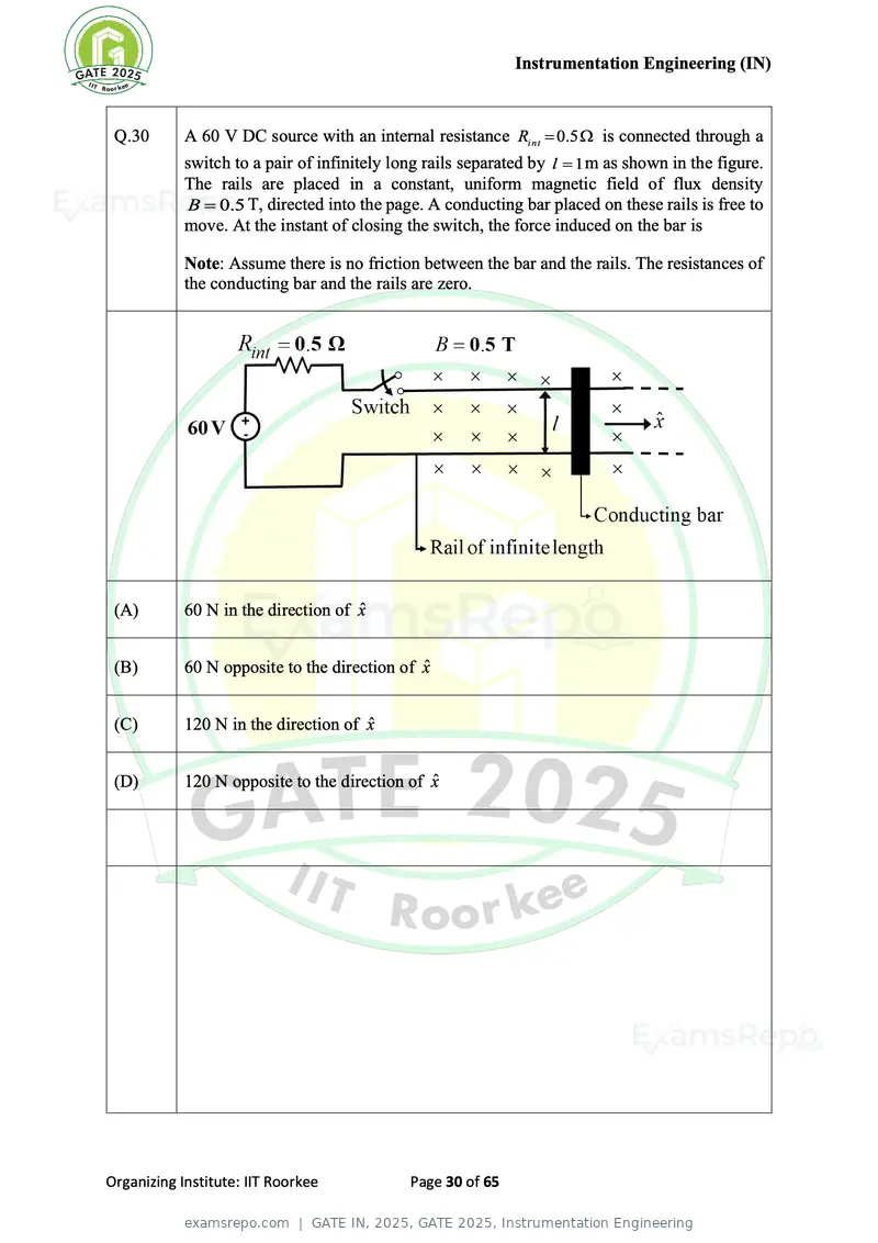
Q.30 A 60 V DC source with an internal resistance Ri nt = 0.5 is connected through a
switch to a pair of infinitely long rails separated by l = 1 m as shown in the figure.
The rails are placed in a constant, uniform magnetic field of flux density
B = 0.5 T, directed into the page. A conducting bar placed on these rails is free to
move. At the instant of closing the switch, the force induced on the bar is
Note: Assume there is no friction between the bar and the rails. The resistances of
the conducting bar and the rails are zero.
(A) 60 N in the direction of x̂
(B) 60 N opposite to the direction of x̂
(C) 120 N in the direction of x̂
(D) 120 N opposite to the direction of x̂
Organizing Institute: IIT Roorkee Page 30 of 65
Text of page 31
Instrumentation Engineering (IN)


 Q.31       The circuits mentioned in the following options are realized using ideal opamp.
            Among these, the circuit(s) performing non-linear operation on the input signal
            is/are


 (A)        Instrumentation amplifier


 (B)        Schmitt trigger


 (C)        Logarithmic amplifier


 (D)        Precision rectifier


Organizing Institute: IIT Roorkee         Page 31 of 65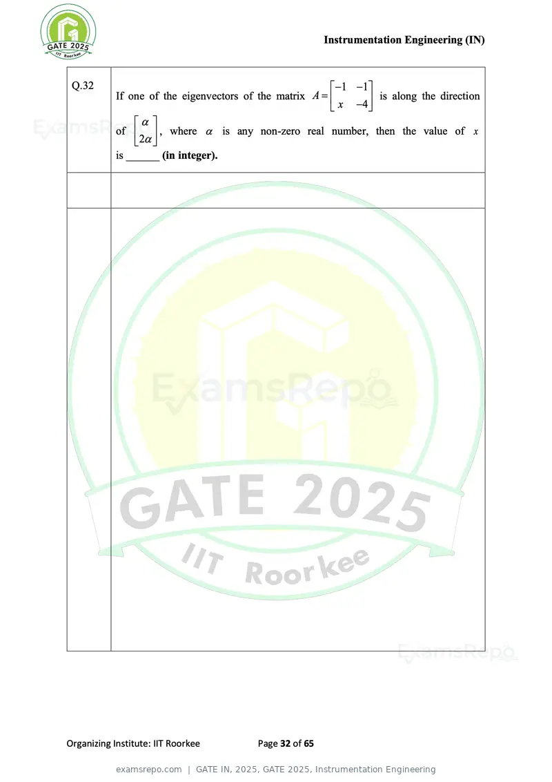
Text of page 32
Instrumentation Engineering (IN)
Q.32 −1 −1
If one of the eigenvectors of the matrix A = is along the direction
x −4
of , where is any non-zero real number, then the value of x
2
is ______ (in integer).
Organizing Institute: IIT Roorkee Page 32 of 65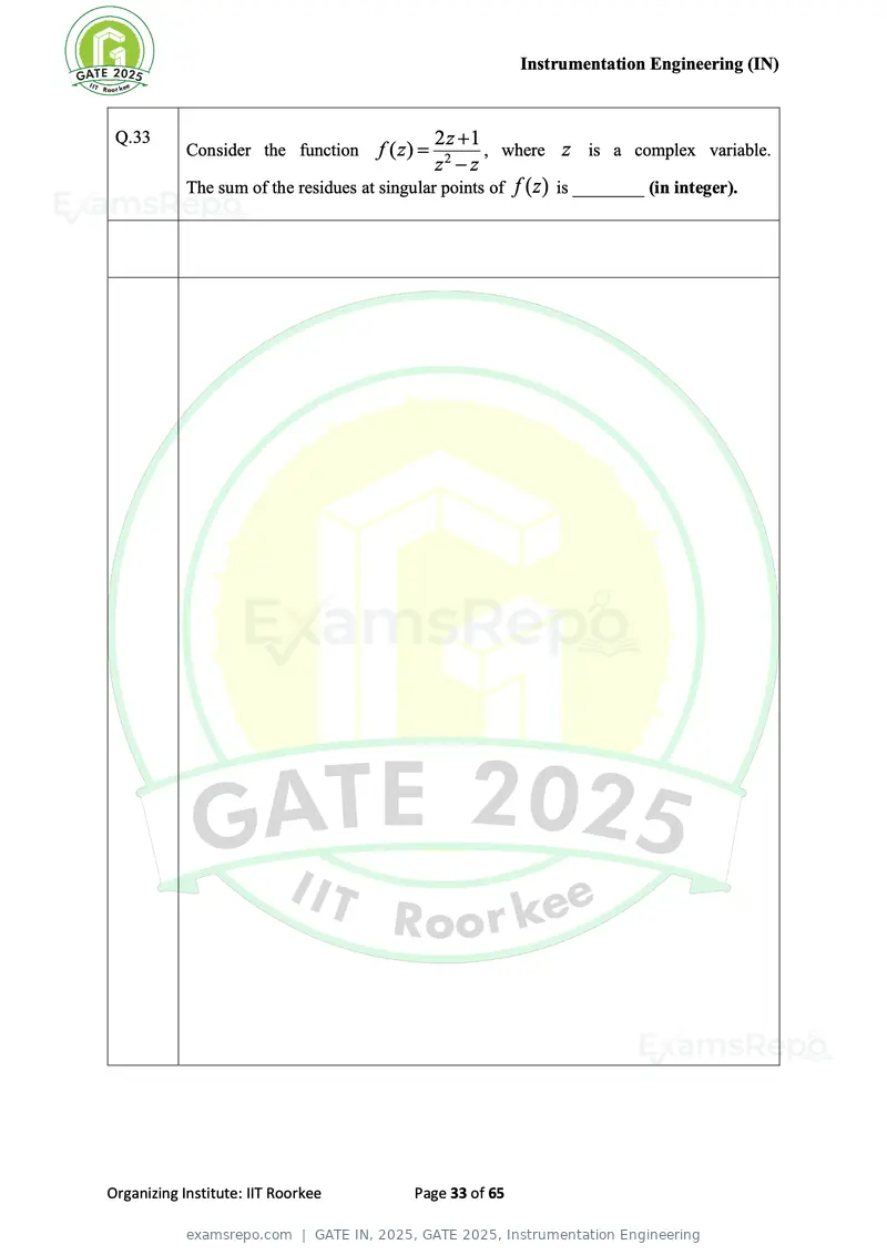
Text of page 33
Instrumentation Engineering (IN)


 Q.33                                             2z +1
            Consider the function      f ( z) =          , where z is a complex variable.
                                                  z2 − z
            The sum of the residues at singular points of f ( z ) is ________ (in integer).


Organizing Institute: IIT Roorkee           Page 33 of 65
Text of page 34
Instrumentation Engineering (IN)


 Q.34       A dual-slope ADC has a fixed integration time of 100 ms. The reference voltage
            of the ADC is − 5 V. The time taken by the ADC to measure an input voltage of
            1.25 V is __________ ms (rounded off to the nearest integer).


Organizing Institute: IIT Roorkee         Page 34 of 65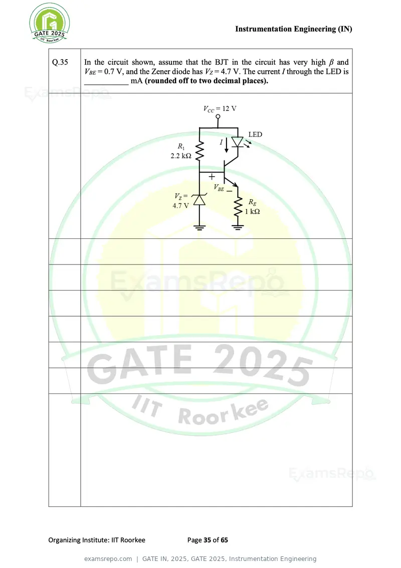
Text of page 35
Instrumentation Engineering (IN)


 Q.35       In the circuit shown, assume that the BJT in the circuit has very high β and
            VBE = 0.7 V, and the Zener diode has VZ = 4.7 V. The current I through the LED is
            ___________ mA (rounded off to two decimal places).


Organizing Institute: IIT Roorkee          Page 35 of 65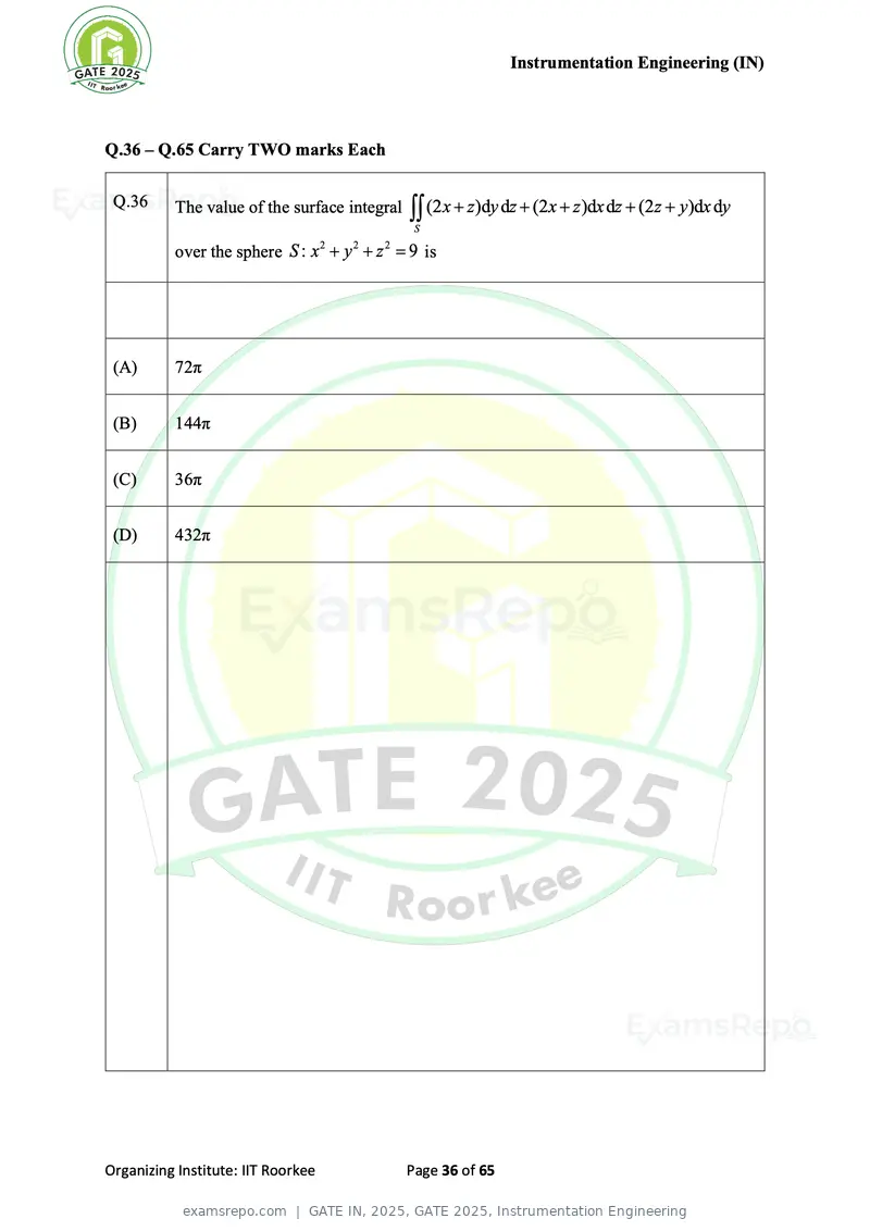
Text of page 36
Instrumentation Engineering (IN)
Q.36 – Q.65 Carry TWO marks Each
Q.36 The value of the surface integral (2 x + z )dy dz + (2 x + z )dx dz + (2 z + y)dx dy
S
over the sphere S : x + y + z = 9 is
2 2 2
(A) 72π
(B) 144π
(C) 36π
(D) 432π
Organizing Institute: IIT Roorkee Page 36 of 65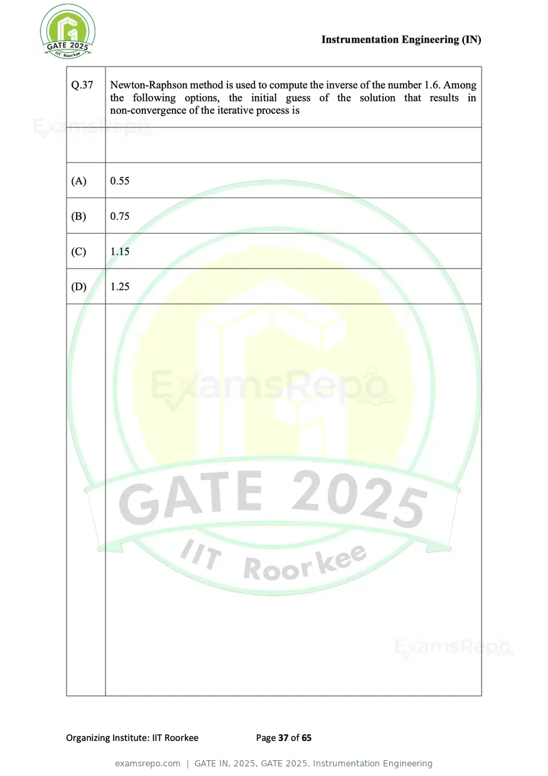
Text of page 37
Instrumentation Engineering (IN)


 Q.37     Newton-Raphson method is used to compute the inverse of the number 1.6. Among
          the following options, the initial guess of the solution that results in
          non-convergence of the iterative process is


 (A)      0.55


 (B)      0.75


 (C)      1.15


 (D)      1.25


Organizing Institute: IIT Roorkee       Page 37 of 65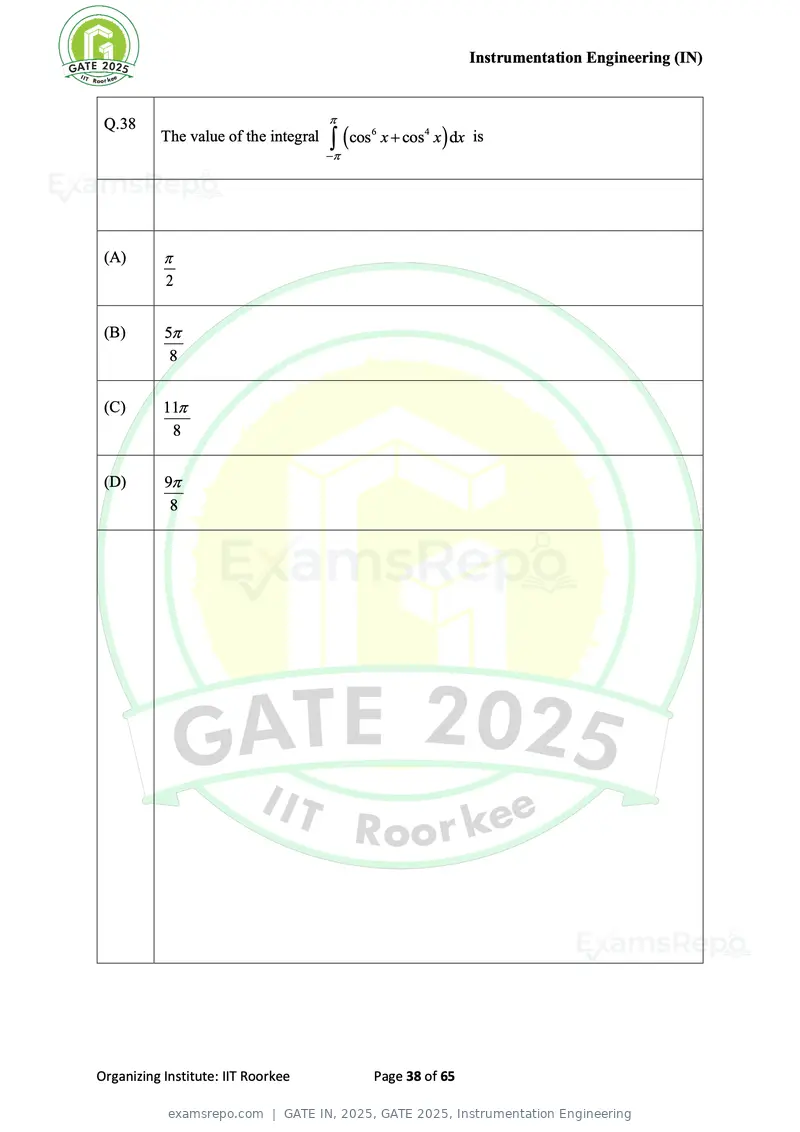
Text of page 38
Instrumentation Engineering (IN)
Q.38
The value of the integral ( cos6 x + cos4 x ) dx is
−
(A)
2
(B) 5
8
(C) 11
8
(D) 9
8
Organizing Institute: IIT Roorkee Page 38 of 65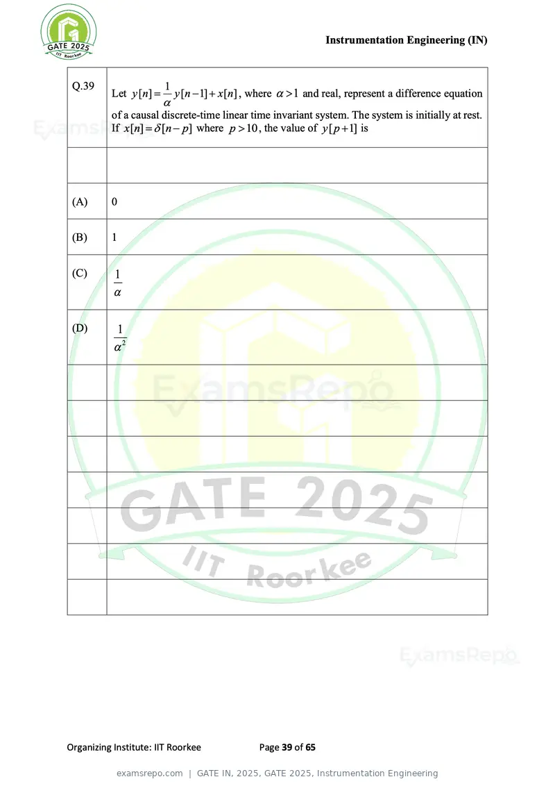
Text of page 39
Instrumentation Engineering (IN)
Q.39 1
Let y [n] = y [n − 1] + x [n] , where 1 and real, represent a difference equation
of a causal discrete-time linear time invariant system. The system is initially at rest.
If x [n] = [n − p] where p 10 , the value of y [ p + 1] is
(A) 0
(B) 1
(C) 1
(D) 1
2
Organizing Institute: IIT Roorkee Page 39 of 65
Text of page 41
Instrumentation Engineering (IN)
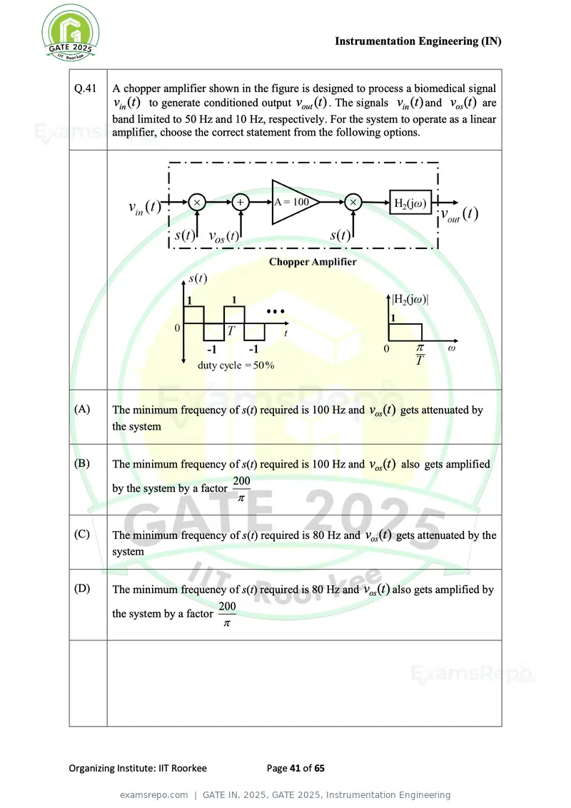
Q.41 A chopper amplifier shown in the figure is designed to process a biomedical signal
vin (t ) to generate conditioned output vout (t ) . The signals vin (t ) and vos (t ) are
band limited to 50 Hz and 10 Hz, respectively. For the system to operate as a linear
amplifier, choose the correct statement from the following options.
(A) The minimum frequency of s(t) required is 100 Hz and vos (t ) gets attenuated by
the system
(B) The minimum frequency of s(t) required is 100 Hz and vos (t ) also gets amplified
200
by the system by a factor
(C) The minimum frequency of s(t) required is 80 Hz and vos (t ) gets attenuated by the
system
(D) The minimum frequency of s(t) required is 80 Hz and vos (t ) also gets amplified by
200
the system by a factor
Organizing Institute: IIT Roorkee Page 41 of 65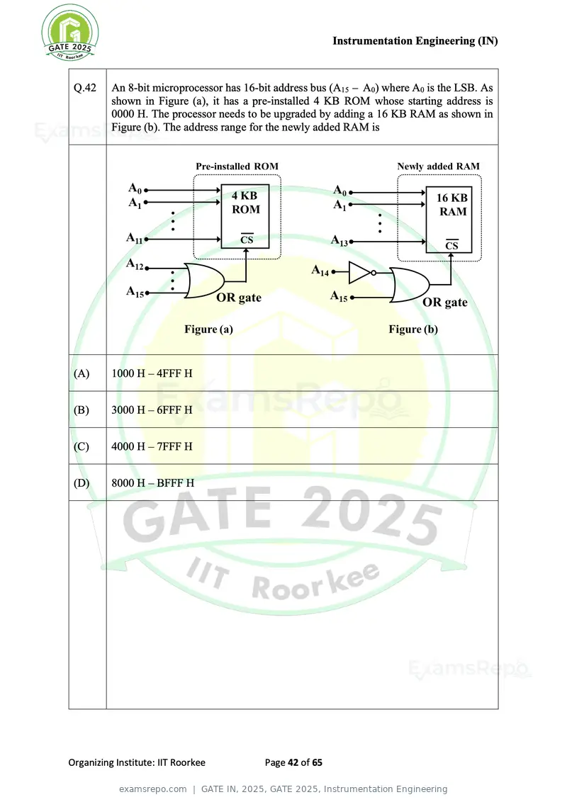
Text of page 42
Instrumentation Engineering (IN)


 Q.42     An 8-bit microprocessor has 16-bit address bus (A15 − A0) where A0 is the LSB. As
          shown in Figure (a), it has a pre-installed 4 KB ROM whose starting address is
          0000 H. The processor needs to be upgraded by adding a 16 KB RAM as shown in
          Figure (b). The address range for the newly added RAM is


 (A)      1000 H – 4FFF H


 (B)      3000 H – 6FFF H


 (C)      4000 H – 7FFF H


 (D)      8000 H – BFFF H


Organizing Institute: IIT Roorkee         Page 42 of 65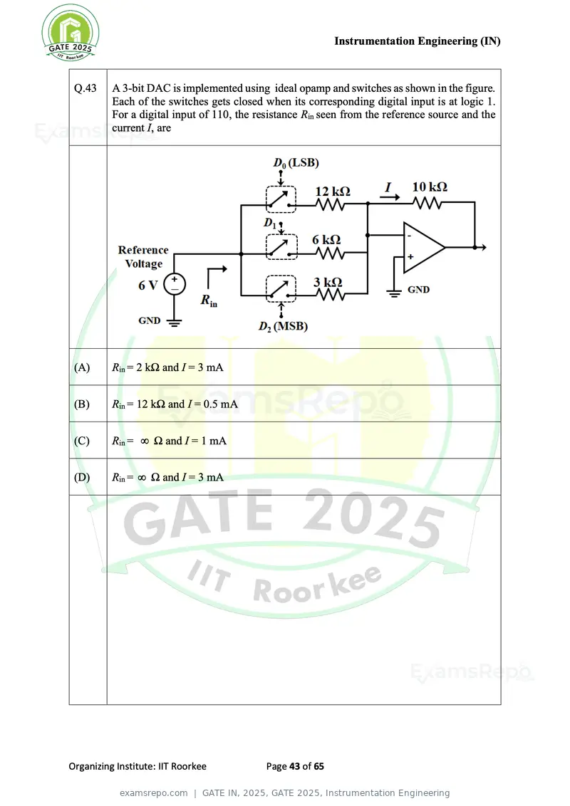
Text of page 43
Instrumentation Engineering (IN)
Q.43 A 3-bit DAC is implemented using ideal opamp and switches as shown in the figure.
Each of the switches gets closed when its corresponding digital input is at logic 1.
For a digital input of 110, the resistance Rin seen from the reference source and the
current I, are
(A) Rin = 2 kΩ and I = 3 mA
(B) Rin = 12 kΩ and I = 0.5 mA
(C) Rin = Ω and I = 1 mA
(D) Rin = Ω and I = 3 mA
Organizing Institute: IIT Roorkee Page 43 of 65
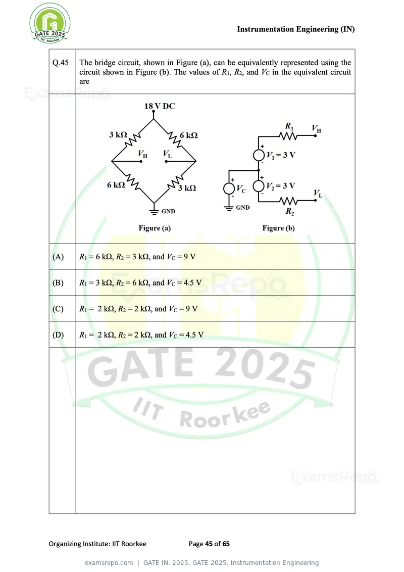
Text of page 45
Instrumentation Engineering (IN)


 Q.45     The bridge circuit, shown in Figure (a), can be equivalently represented using the
          circuit shown in Figure (b). The values of R1, R2, and VC in the equivalent circuit
          are


 (A)      R1 = 6 kΩ, R2 = 3 kΩ, and VC = 9 V


 (B)      R1 = 3 kΩ, R2 = 6 kΩ, and VC = 4.5 V


 (C)      R1 = 2 kΩ, R2 = 2 kΩ, and VC = 9 V


 (D)      R1 = 2 kΩ, R2 = 2 kΩ, and VC = 4.5 V


Organizing Institute: IIT Roorkee          Page 45 of 65
Text of page 46
Instrumentation Engineering (IN)


 Q.46     A 2-pole, 50 Hz, 3-phase induction motor supplies power to a certain load at
          2970 rpm. The torque-speed curve of this machine follows a linear relationship
          between synchronous speed and 95 % of synchronous speed. Assume mechanical
          and stray losses to be zero. If the load torque of the motor is doubled, the new
          operating speed of the motor, in rpm, is


 (A)      2940


 (B)      2812


 (C)      2970


 (D)      2850


Organizing Institute: IIT Roorkee         Page 46 of 65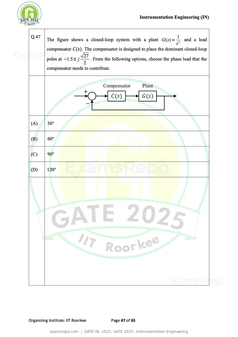
Text of page 47
Instrumentation Engineering (IN)
Q.47 1
The figure shows a closed-loop system with a plant G ( s ) = and a lead
s2
compensator C(s). The compensator is designed to place the dominant closed-loop
27
poles at − 1.5 j . From the following options, choose the phase lead that the
2
compensator needs to contribute.
(A) 30
(B) 60
(C) 90
(D) 120
Organizing Institute: IIT Roorkee Page 47 of 65
Text of page 48
Instrumentation Engineering (IN)
Q.48 Let f (t ) and g (t ) represent continuous-time real-valued signals. If h (t ) denotes
cross-correlation between f (t ) and g (−t ) , its continuous-time Fourier transform
H ( j) equals
Note: F ( j) and G( j) denote the continuous-time Fourier transforms of f (t )
and g (t ) , respectively.
(A) F ( j) G( j)
(B) F (− j) G( j)
(C) F ( j) G(− j)
(D) −F ( j) G(− j)
Organizing Institute: IIT Roorkee Page 48 of 65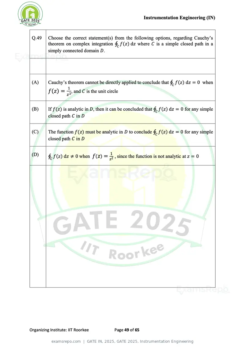
Text of page 49
Instrumentation Engineering (IN)


 Q.49     Choose the correct statement(s) from the following options, regarding Cauchy’s
          theorem on complex integration ∮C f(z) dz where C is a simple closed path in a
          simply connected domain D.


 (A)      Cauchy’s theorem cannot be directly applied to conclude that ∮C f(z) dz = 0 when
                     1
          f(z) = 2, and C is the unit circle
                    z


 (B)      If f(z) is analytic in D, then it can be concluded that ∮C f(z) dz = 0 for any simple
          closed path C in D


 (C)      The function f(z) must be analytic in D to conclude ∮C f(z) dz = 0 for any simple
          closed path C in D


 (D)                                     1
          ∮C f(z) dz ≠ 0 when f(z) = z2 , since the function is not analytic at z = 0


Organizing Institute: IIT Roorkee            Page 49 of 65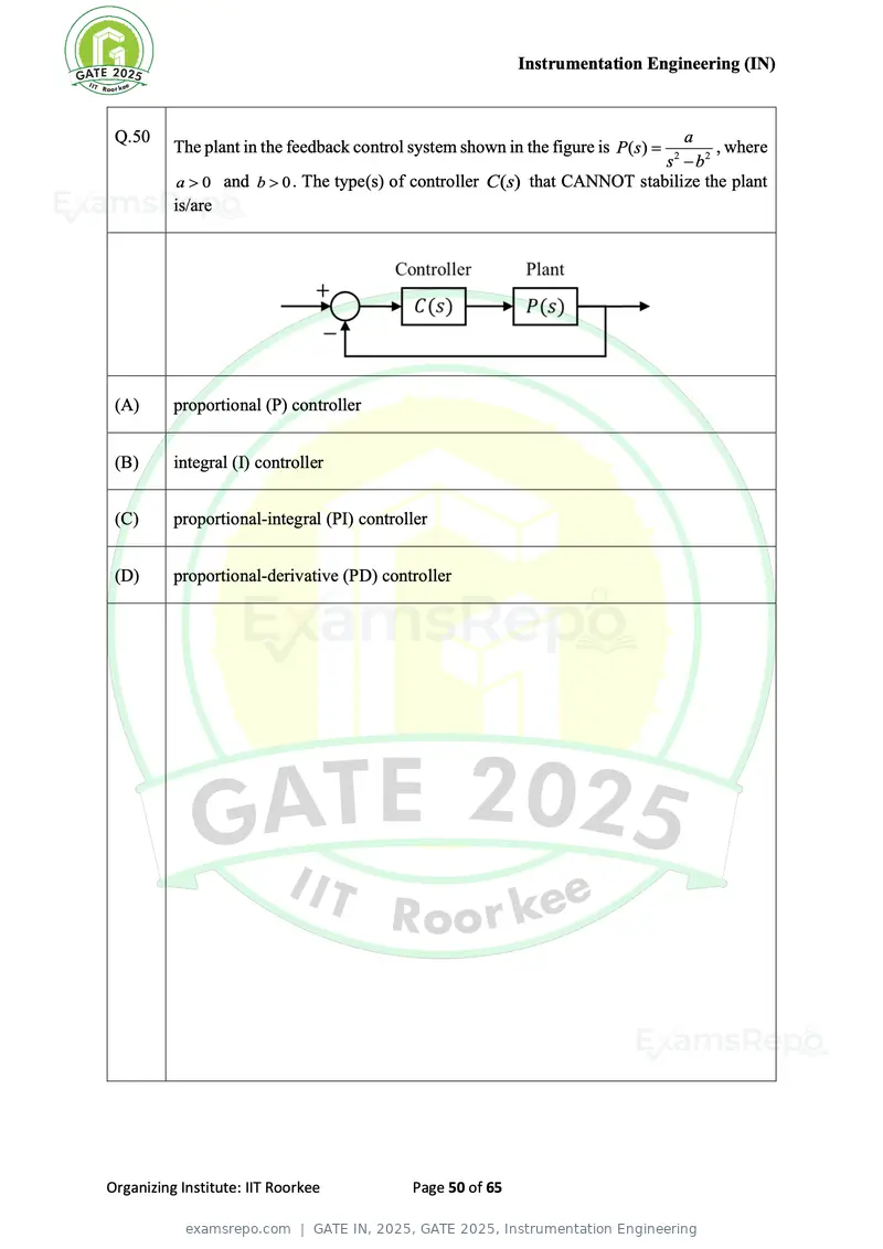
Text of page 50
Instrumentation Engineering (IN)
Q.50 a
The plant in the feedback control system shown in the figure is P( s) = , where
s − b2 2
a 0 and b 0 . The type(s) of controller C(s) that CANNOT stabilize the plant
is/are
(A) proportional (P) controller
(B) integral (I) controller
(C) proportional-integral (PI) controller
(D) proportional-derivative (PD) controller
Organizing Institute: IIT Roorkee Page 50 of 65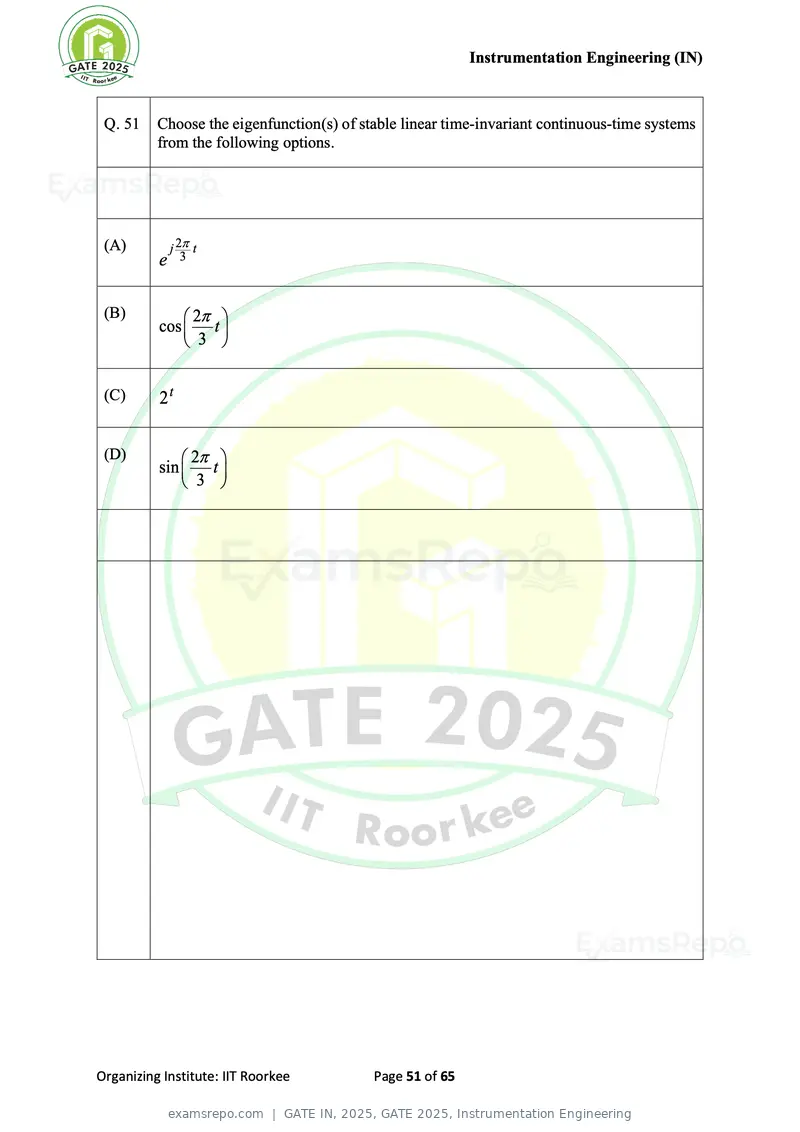
Text of page 51
Instrumentation Engineering (IN)
Q. 51 Choose the eigenfunction(s) of stable linear time-invariant continuous-time systems
from the following options.
(A) j 2 t
e 3
(B) 2
cos t
3
(C) 2t
(D) 2
sin t
3
Organizing Institute: IIT Roorkee Page 51 of 65
Text of page 52
Instrumentation Engineering (IN)


 Q.52      The probability of a student missing a class is 0.1. In a total number of 10 classes,
           the probability that the student will not miss more than one class is ___ (rounded
           off to two decimal places).


Organizing Institute: IIT Roorkee           Page 52 of 65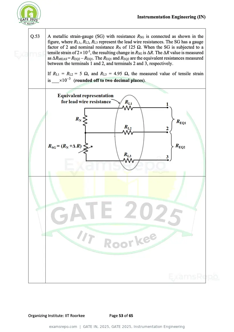
Text of page 53
Instrumentation Engineering (IN)
Q.53 A metallic strain-gauge (SG) with resistance RSG is connected as shown in the
figure, where RL1, RL2, RL3 represent the lead wire resistances. The SG has a gauge
factor of 2 and nominal resistance RN of 125 Ω. When the SG is subjected to a
tensile strain of 2 10-3, the resulting change in RSG is ΔR. The ΔR value is measured
as ΔRMEAS = REQ2 – REQ1. The REQ1 and REQ2 are the equivalent resistances measured
between the terminals 1 and 2, and terminals 2 and 3, respectively.
If RL1 = RL2 = 5 Ω, and RL3 = 4.95 Ω, the measured value of tensile strain
is ___ 10 −3 (rounded off to two decimal places).
Organizing Institute: IIT Roorkee Page 53 of 65
Text of page 54
Instrumentation Engineering (IN)
Q.54 ( )
Let X e j represent the discrete time Fourier transform of a 4-length sequence
( ) is sampled at
x[n] , where x[0] = 1, x[1] = 2, x[2] = 2, and x[3] = 4 . X e j
2 k
k = to generate a periodic sequence in k with period 3, where k represents
3
an integer. Let y [n] represent another sequence such that its discrete Fourier
( ) for 0 k 2 . The value of y[0]
j
transform Y [k ] is given as Y [k ] = X e k
is______ (in integer).
Organizing Institute: IIT Roorkee Page 54 of 65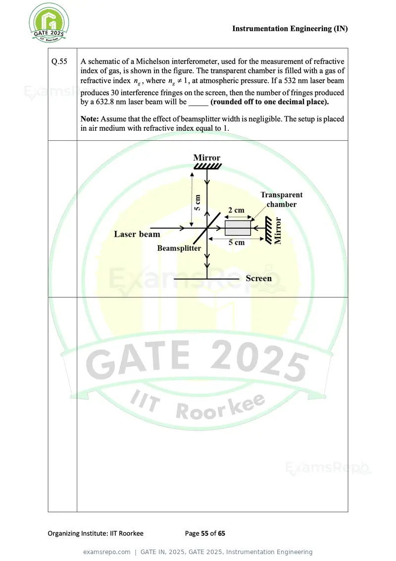
Text of page 55
Instrumentation Engineering (IN)
Q.55 A schematic of a Michelson interferometer, used for the measurement of refractive
index of gas, is shown in the figure. The transparent chamber is filled with a gas of
refractive index ng , where ng 1 , at atmospheric pressure. If a 532 nm laser beam
produces 30 interference fringes on the screen, then the number of fringes produced
by a 632.8 nm laser beam will be _____ (rounded off to one decimal place).
Note: Assume that the effect of beamsplitter width is negligible. The setup is placed
in air medium with refractive index equal to 1.
Organizing Institute: IIT Roorkee Page 55 of 65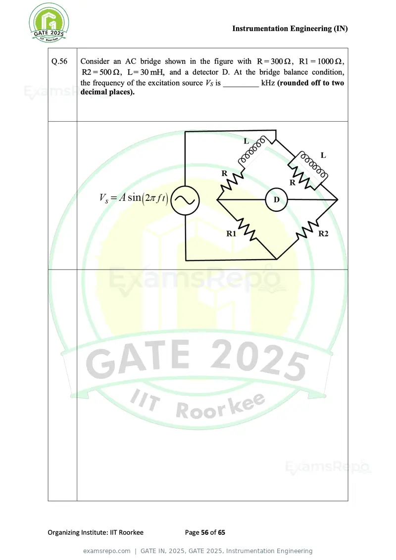
Text of page 56
Instrumentation Engineering (IN)


 Q.56      Consider an AC bridge shown in the figure with R = 300 Ω , R1 = 1000 Ω ,
            R2 = 500 Ω , L= 30 mH, and a detector D. At the bridge balance condition,
           the frequency of the excitation source VS is _________ kHz (rounded off to two
           decimal places).


Organizing Institute: IIT Roorkee        Page 56 of 65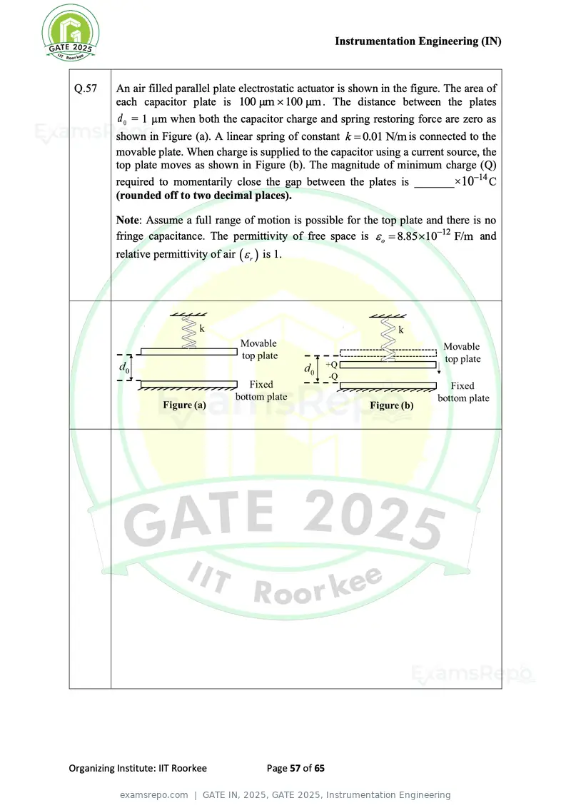
Text of page 57
Instrumentation Engineering (IN)
Q.57 An air filled parallel plate electrostatic actuator is shown in the figure. The area of
each capacitor plate is 100 μm 100 μm . The distance between the plates
d 0 = 1 µm when both the capacitor charge and spring restoring force are zero as
shown in Figure (a). A linear spring of constant k = 0.01 N/m is connected to the
movable plate. When charge is supplied to the capacitor using a current source, the
top plate moves as shown in Figure (b). The magnitude of minimum charge (Q)
required to momentarily close the gap between the plates is _______× 10−14 C
(rounded off to two decimal places).
Note: Assume a full range of motion is possible for the top plate and there is no
fringe capacitance. The permittivity of free space is o = 8.85 10−12 F/m and
relative permittivity of air ( r ) is 1.
Organizing Institute: IIT Roorkee Page 57 of 65
Text of page 58
Instrumentation Engineering (IN)


 Q.58      The resistance of a thermistor is measured to be 2.25 kΩ at 30 °C and 1.17 kΩ at
           60 °C. Its material constant β is ___________ K (rounded off to two decimal
           places).


Organizing Institute: IIT Roorkee         Page 58 of 65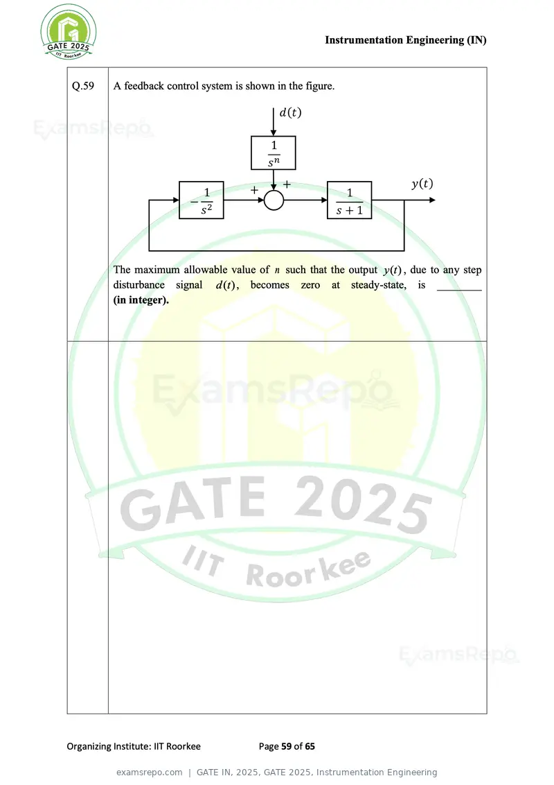
Text of page 59
Instrumentation Engineering (IN)


 Q.59      A feedback control system is shown in the figure.


           The maximum allowable value of n such that the output y(t ) , due to any step
           disturbance signal d (t ) , becomes zero at steady-state, is ________
           (in integer).


Organizing Institute: IIT Roorkee          Page 59 of 65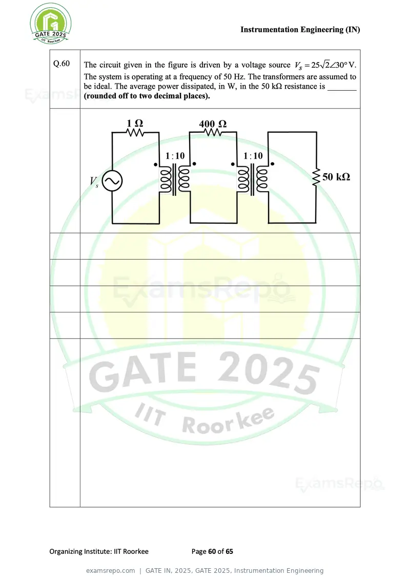
Text of page 60
Instrumentation Engineering (IN)
Q.60 The circuit given in the figure is driven by a voltage source Vs = 25 230 V.
The system is operating at a frequency of 50 Hz. The transformers are assumed to
be ideal. The average power dissipated, in W, in the 50 kΩ resistance is _______
(rounded off to two decimal places).
Organizing Institute: IIT Roorkee Page 60 of 65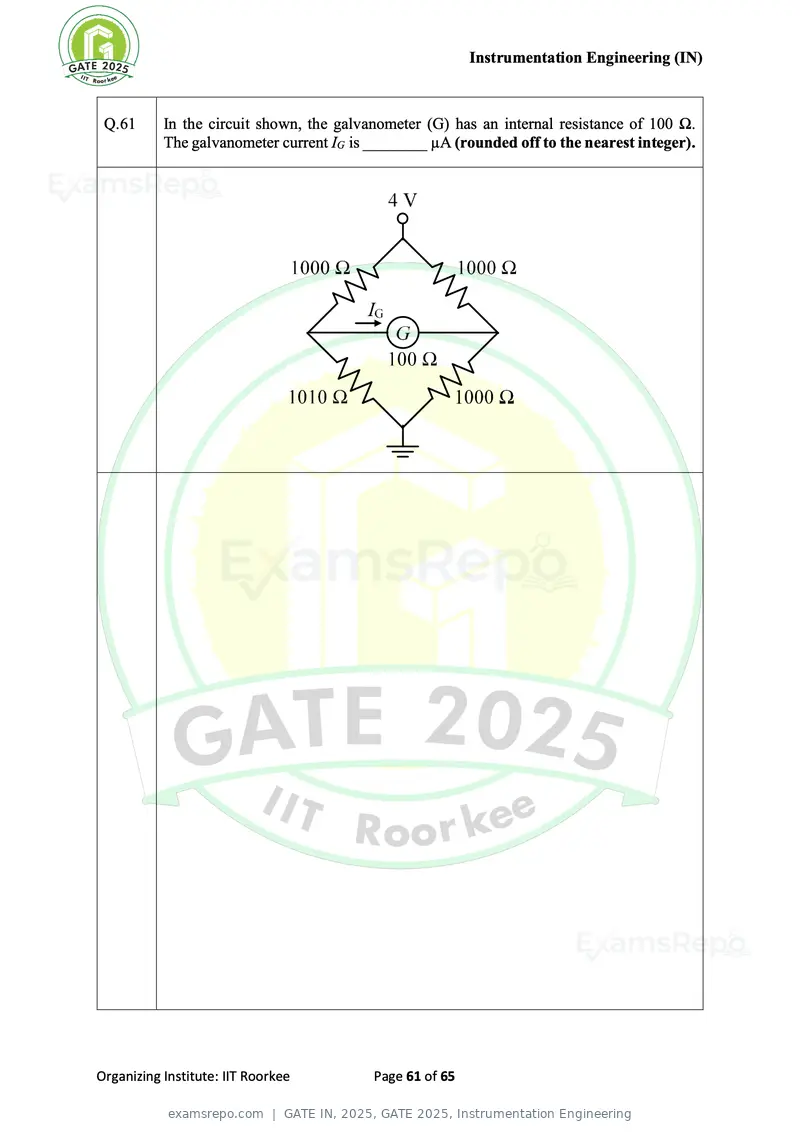
Text of page 61
Instrumentation Engineering (IN)


 Q.61      In the circuit shown, the galvanometer (G) has an internal resistance of 100 Ω.
           The galvanometer current IG is ________ µA (rounded off to the nearest integer).


Organizing Institute: IIT Roorkee         Page 61 of 65
Text of page 62
Instrumentation Engineering (IN)


 Q.62      A series RLC circuit resonates at 7500 rad/s for inductance
           L = 20 mH and resistance R = 10 Ω. The uncertainties in the measurement of L and
           R are 0.8 mH and 0.3 Ω, respectively. The percentage uncertainty in the
           measurement of quality factor is _________% (rounded off to one decimal
           place).


Organizing Institute: IIT Roorkee         Page 62 of 65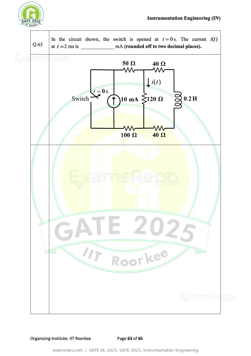
Text of page 63
Instrumentation Engineering (IN)


           In the circuit shown, the switch is opened at t = 0 s. The current i(t )
 Q.63      at t = 2 ms is _____________ mA (rounded off to two decimal places).


Organizing Institute: IIT Roorkee      Page 63 of 65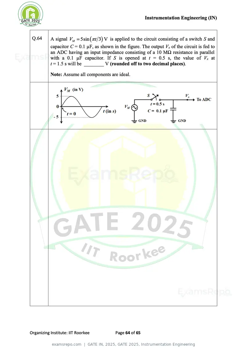
Text of page 64
Instrumentation Engineering (IN)
Q.64 A signal VM = 5sin ( t 3) V is applied to the circuit consisting of a switch S and
capacitor C = 0.1 µF, as shown in the figure. The output Vx of the circuit is fed to
an ADC having an input impedance consisting of a 10 MΩ resistance in parallel
with a 0.1 µF capacitor. If S is opened at t = 0.5 s, the value of Vx at
t = 1.5 s will be ________ V (rounded off to two decimal places).
Note: Assume all components are ideal.
Organizing Institute: IIT Roorkee Page 64 of 65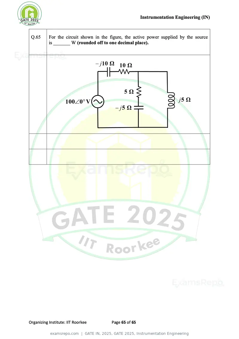
Text of page 65
Instrumentation Engineering (IN)


 Q.65      For the circuit shown in the figure, the active power supplied by the source
           is _______ W (rounded off to one decimal place).


Organizing Institute: IIT Roorkee        Page 65 of 65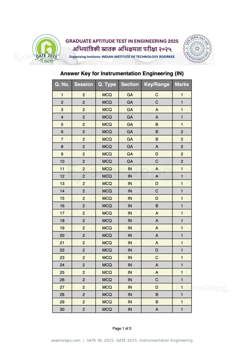
Text of page 1
Answer Key for Instrumentation Engineering (IN)

Q. No. Session   Q. Type    Section   Key/Range   Marks

  1       2       MCQ           GA       C          1
  2       2       MCQ           GA       C          1
  3       2       MCQ           GA        A         1
  4       2       MCQ           GA        A         1
  5       2       MCQ           GA        B         1
  6       2       MCQ           GA        B         2
  7       2       MCQ           GA        B         2
  8       2       MCQ           GA        A         2
  9       2       MCQ           GA       D          2
 10       2       MCQ           GA       C          2
 11       2       MCQ           IN        A         1
 12       2       MCQ           IN        A         1
 13       2       MCQ           IN       D          1
 14       2       MCQ           IN       C          1
 15       2       MCQ           IN       D          1
 16       2       MCQ           IN        B         1
 17       2       MCQ           IN        A         1
 18       2       MCQ           IN        A         1
 19       2       MCQ           IN        A         1
 20       2       MCQ           IN        A         1
 21       2       MCQ           IN        A         1
 22       2       MCQ           IN       D          1
 23       2       MCQ           IN       C          1
 24       2       MCQ           IN        A         1
 25       2       MCQ           IN        A         1
 26       2       MCQ           IN       C          1
 27       2       MCQ           IN       D          1
 28       2       MCQ           IN        B         1
 29       2       MCQ           IN        B         1
 30       2       MCQ           IN        A         1


                        Page 1 of 2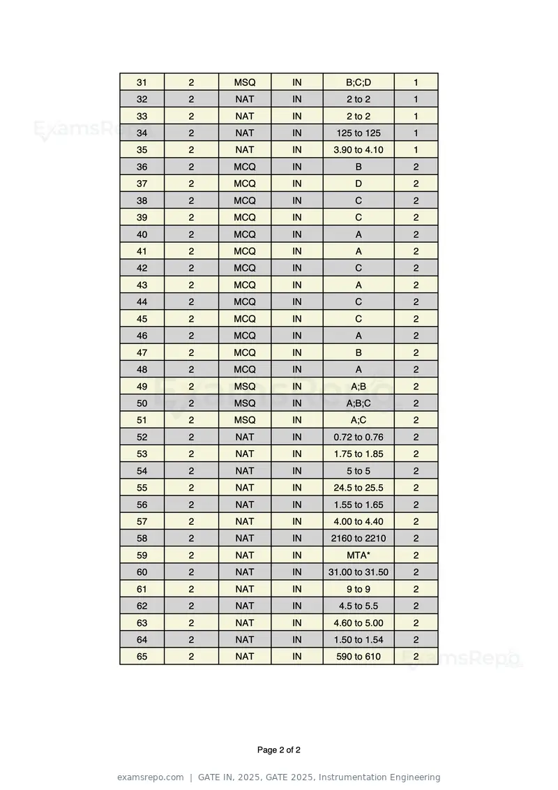
Text of page 2
31          2     MSQ           IN        B;C;D        1
   32          2     NAT           IN        2 to 2       1
   33          2     NAT           IN        2 to 2       1
   34          2     NAT           IN     125 to 125      1
   35          2     NAT           IN     3.90 to 4.10    1
   36          2     MCQ           IN          B          2
   37          2     MCQ           IN          D          2
   38          2     MCQ           IN          C          2
   39          2     MCQ           IN          C          2
   40          2     MCQ           IN          A          2
   41          2     MCQ           IN          A          2
   42          2     MCQ           IN          C          2
   43          2     MCQ           IN          A          2
   44          2     MCQ           IN          C          2
   45          2     MCQ           IN          C          2
   46          2     MCQ           IN          A          2
   47          2     MCQ           IN          B          2
   48          2     MCQ           IN          A          2
   49          2     MSQ           IN         A;B         2
   50          2     MSQ           IN        A;B;C        2
   51          2     MSQ           IN         A;C         2
   52          2     NAT           IN     0.72 to 0.76    2
   53          2     NAT           IN     1.75 to 1.85    2
   54          2     NAT           IN        5 to 5       2
   55          2     NAT           IN     24.5 to 25.5    2
   56          2     NAT           IN     1.55 to 1.65    2
   57          2     NAT           IN     4.00 to 4.40    2
   58          2     NAT           IN    2160 to 2210     2
   59          2     NAT           IN        MTA*         2
   60          2     NAT           IN    31.00 to 31.50   2
   61          2     NAT           IN        9 to 9       2
   62          2     NAT           IN      4.5 to 5.5     2
   63          2     NAT           IN     4.60 to 5.00    2
   64          2     NAT           IN     1.50 to 1.54    2
   65          2     NAT           IN     590 to 610      2
*MTA= Marks To All


                           Page 2 of 2
Page 1 of 65
Source: GATE. Question paper published by GATE.