
JPSC Assistant Engineer 2021: Assistant Engineer Written Exam, Advt. No. 08/2018 and 08/2019, ELECTRICAL ENGINEERING PAPER-II SUBJECT-CODE-13
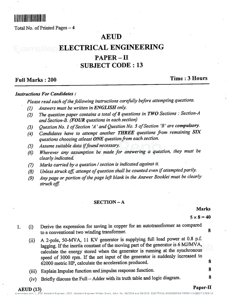
Text of page 1
llllll!llulllllllllllunlRI


Total No. of printed Pages -4

                                                     AEUD
                               ELECTRICAL ENGINEHRING
                                             PAPER - 11
                                          SUBJFCT CODE : 13

Full Marks : 200                                                                          Time : 3 Hours

Iiestructious For Candidates :
          Please read each Of the following iustructious caref ally bef lore attempting questions.
          (1)        Ariswers must be written in ENGLISH only.
           (2)      The question paper contains a total Of 8 questions in TWO Sections : Section-A
                    and Section-B. aTOUR questions in each section)
           (3)       Question No.1 Of section `A' and Question No. 5 Of section `B' are compulsop=
           (4)      Candidates have to attempt another THpeE qu_esttous from remaining SIX
                    questions choosing atleast ONE question from each section.
           (5)       Assume suitable data if f ;ound necessary.
           (6)       Wherever any assumption be pnde for answering a question, they must be
                     clearly indicated.
           q)        Marks carried by a question / section is indicated against it.
           (8)       Unless struck of f ; attempt of question shall be counted even if attempted partly.
           (9)       Any page or portion of the page lef i blank in the Answer Booklet must be clearly
                     struckoff


                                                 SECTION - A
                                                                                                     Marks
                                                                                                  5 x 8 - 40
  1.         (i)      Derive the expression for saving in copper for an autotransformer as compared
                     to a conventional two winding transformer.
            (ii)       A 2-pole, 50-MVA,11 KV generator is supplying full load power at 0.8 p.f.
                      lagging.Iftheinertiacoustautofthemovingpartofthegeneratoris6MJ/MVA,
                      calculate the energy stored when the generator is running at the synchronous
                      speed of 3000 rpm. If the net input of the generator is suddenly increased to
                      62000 metric IIT, calculate the acceleration produced
            (iii)     Explain Impulse function and impulse response function.
            (iv)      Briefly discuss the Full - Adder with its truth table and logic diagram.

   AEUD (13)                                                                                        Paper-II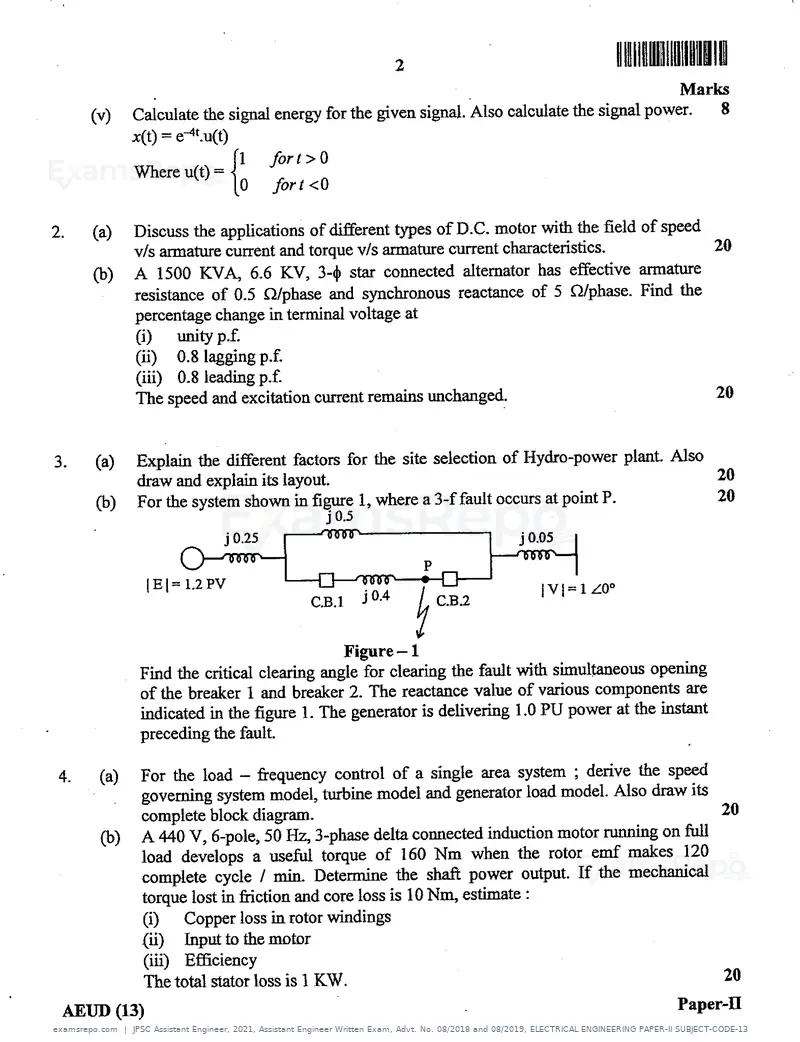
Text of page 2
lllllllNIlll»lllllHINI


                                                                                               Marks
     (v)    Calculate the signal energy for the given signal. Also calculate the signal power.
            a;(t) - e4t.u(t)
                             1   fiort=0
            where u(t) =
                           0        fort=0

2.   (a)    Discuss the applications of different types ofD.C. motor with the field of speed
            v/s armature current and torque v/s armature current characteristics.            20

     a)     A 1500 KVA, 6.6 KV, 3-a star cormected alternator has effective armature
            resistance of 0.5 a/phase and synchronous reactance of 5 a/phase. Find the
            percentage change in teminal voltage at
            (i)   unityp.f.
            (ii)  0.8 laggingp.f.
            (iii) 0.8 leadingp.f.
            The speed and excitation current remains unchanged.                                       20


     (a)    Explain the different factors for the site selection of Hydro-power plant. Also
            draw and explain its layout.
     qJ)     For the system shown in fiT#: 1, where a 3-ffault occur at point p.


                                             Figure - 1
             Find the critical clearing angle for clearing the fault with simultaneous opening
             of the breaker 1 and breaker 2. The reactance value of various components are
             indicated in the figure 1. The generator is delivering I.0 PU power at the instant
             preceding the fault.

      (a)    For the load - fi.equency control of a single area system ; derive the speed
             governing system model, turbine model and generator load model. Also draw its
             complete block diagram.                                                       20

      a)     A 440 V, 6-pole, 50 Hz, 3-phase delta comected induction motor rmning on full
             load develops a usefu torque of 160 Nm when the rotor emf makes 120
             complete cycle / min. Deteine the shaft power output. If the mechanical
             torque lost in friction and core loss is 10 Nm, estimate :
             (i)   Copperloss inrotorwindings
             (ii) Inputto themotor
             (iii) Efficiency
             The total stator loss is 1 KW.                                                             20

 AEUD (13)                                                                                     Paper-H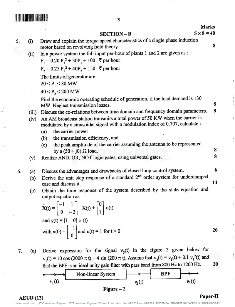
Text of page 3
IIIlllrmllHIIIInlll                                    3
                                                                                                   Marks
                                              SECTION-B                                         5 x 8 =40
       (i)     Draw and explain the torque speed characteristics ofa single phase induedon
               motor based on revolving field theory.
       (ii)    In a power system the full input per-hour of plants 1 and 2 are given as :
               F, = 0.20 P[2 + 30P, + 100 { perhour
               F2 = 0.25 P22 + 40P2 + 150 i per hour
               The linits of generator are
               20 S P, i 80 MW
               40 S P2 S 200 MW
               Find the economic operating schedule of generation, if the load demand is 130
               MW. Negleet transmission losses.
       (iii)   Discuss the co-relations between time domain and frequency domain parameters.
       (iv)    An AM broadcast station transmits a total power of 50 KW when the carrier is
               modulated by a sinusoidal signal with a modulation index of 0.707, calculate :
               (a)     the carrierpower
               a)     the transmission efficiency, and
               (c)     the peak amplitude of the carrier assuming the antenna to be represented
                       by a (50 +jo) a load.
        (v)    Realize AND, OR, NOT logic gates, using universal gates.

        (a)    Discuss the advantages and drawbacks of closed loop control system.
        a))    Derive the unit step response of a standard 2ad order system for underdamped
               case and discuss it.
        (c)    Obtain the time response of the system described by the state equation and
               output equation as

               i(t,-[-ol-12]X(t,+[:]u,t,

               andy(t)-[1       0]x(t)

               with x(0) -        and u(t) = 1 for t > 0                                                   20


 7.     (a)     Derive expression for the sigrial v3(t) in the figure 2 given below for
                v](t) = 10 cos (2000 n t) + 4 sin (200 tt t). Assume that v2(t) = v[(t) + 0.1 v[2(t) and
                that the BPF is an ideal unity gain filter with pass band from 800 Hz to 1200 Hz.
                                 Non-linear System
                                                                y2(t)
                                               Figure-2
  AEUD (13)                                                                                        Paper-H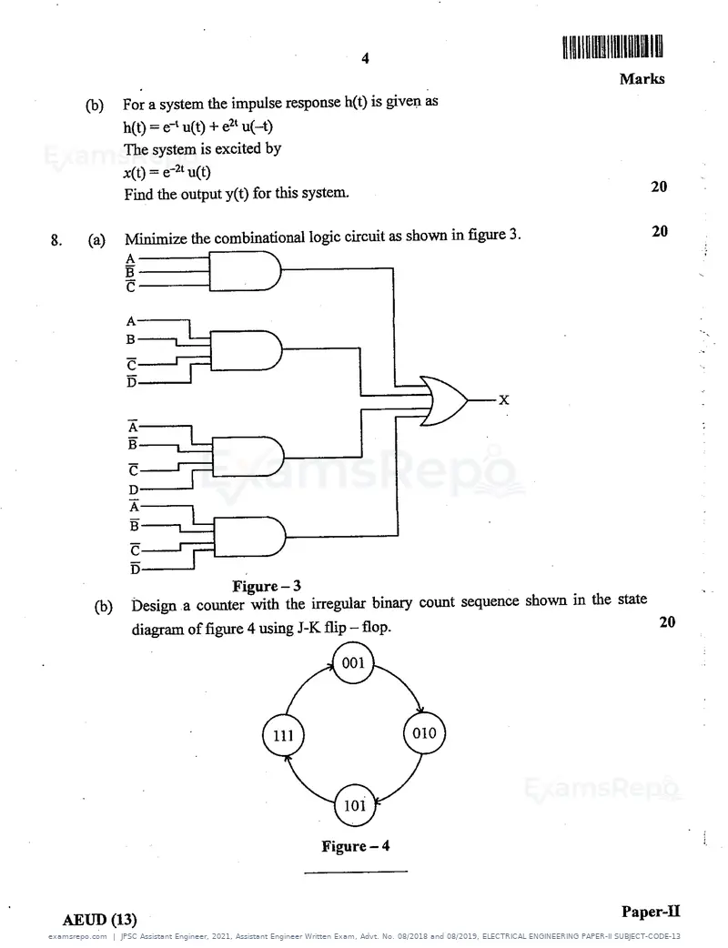
Text of page 4
lll!llllIRIlllllllllIAIEN


                                                                                           Marlrs
     a)    For a system the impulse response h(t) is given as
            h{t) = e-t u(t) + e2t u(_t)
           The system is excited by
           J:(t) - e-2t u(t)
                                                                                                   20
           Find the output y(t) for this system.

                                                                                                   20
8.   (a)    Minimize the combinational logic circuit as shown in figure 3.


                               Figure - 3
      a)    Design a counter with the irregular binary count sequence shown in the state
                                                                                         20
            diagram of figure 4 using J-K flip - flop.


                                                                                           Paper-II
 iREUD (13)
Official key not published for this paper.
Page 1 of 4
Source: Jharkhand Public Service Commission. Question paper published by Jharkhand Public Service Commission.