
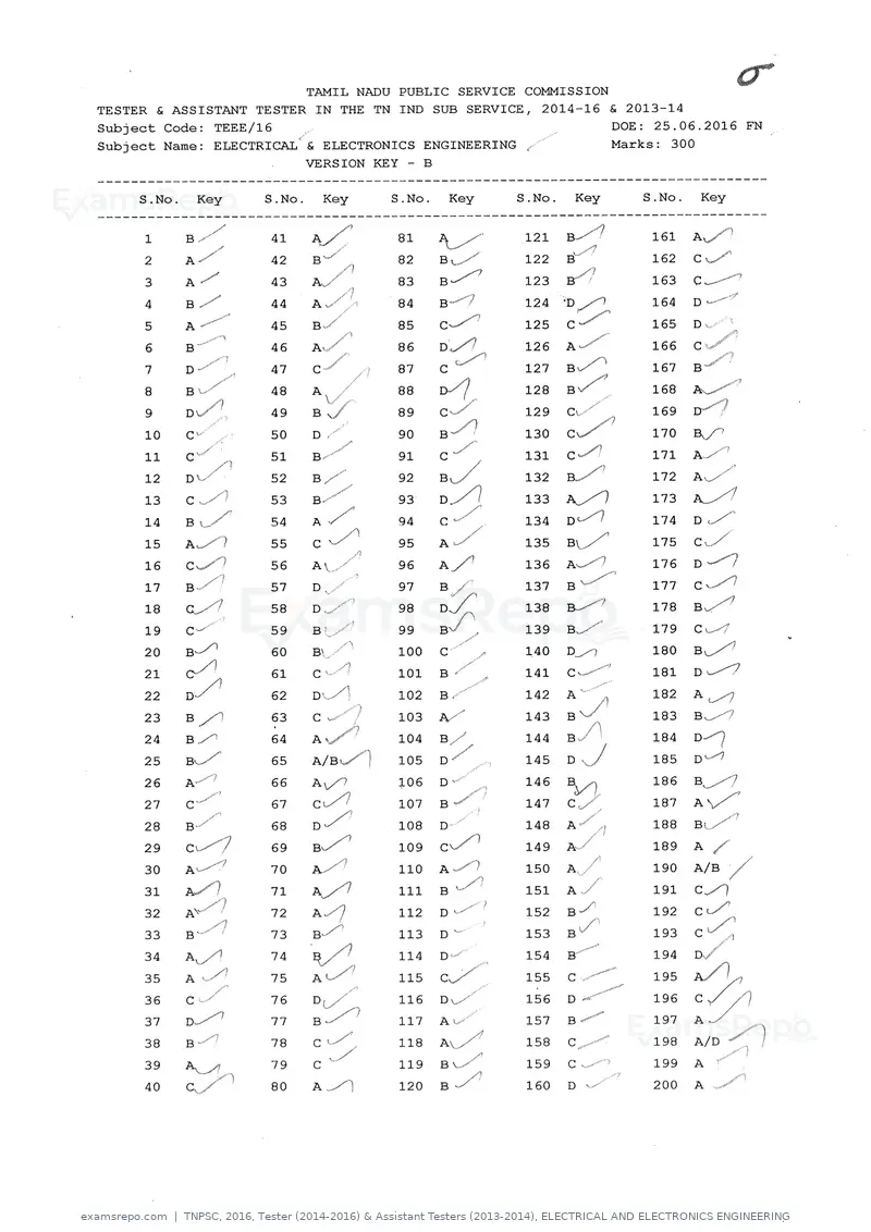
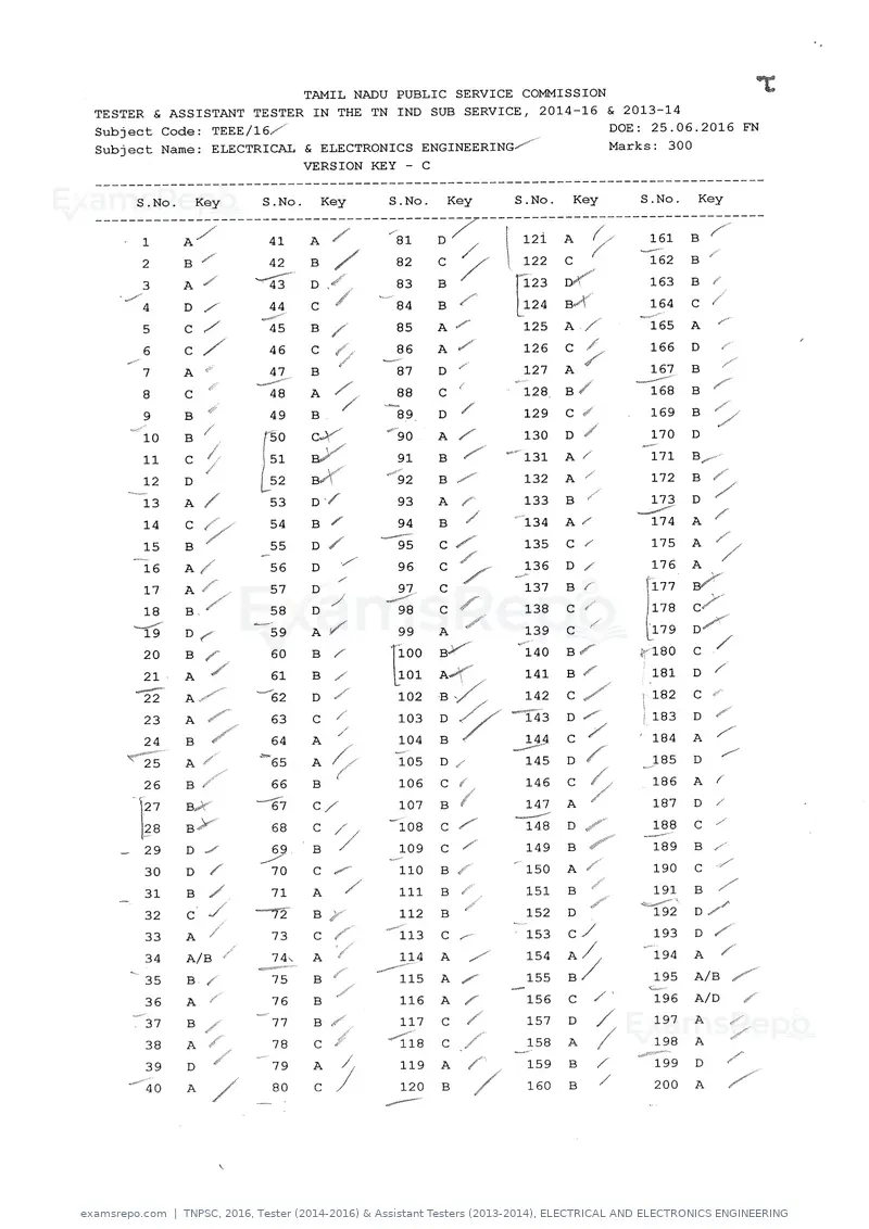
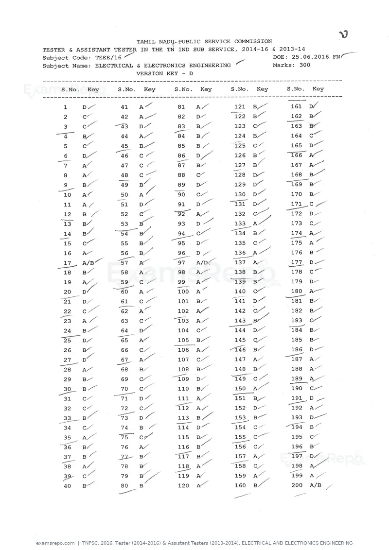
TNPSC 2016: Tester (2014-) & Assistant Testers (2013-2014), ELECTRICAL AND ELECTRONICS ENGINEERING
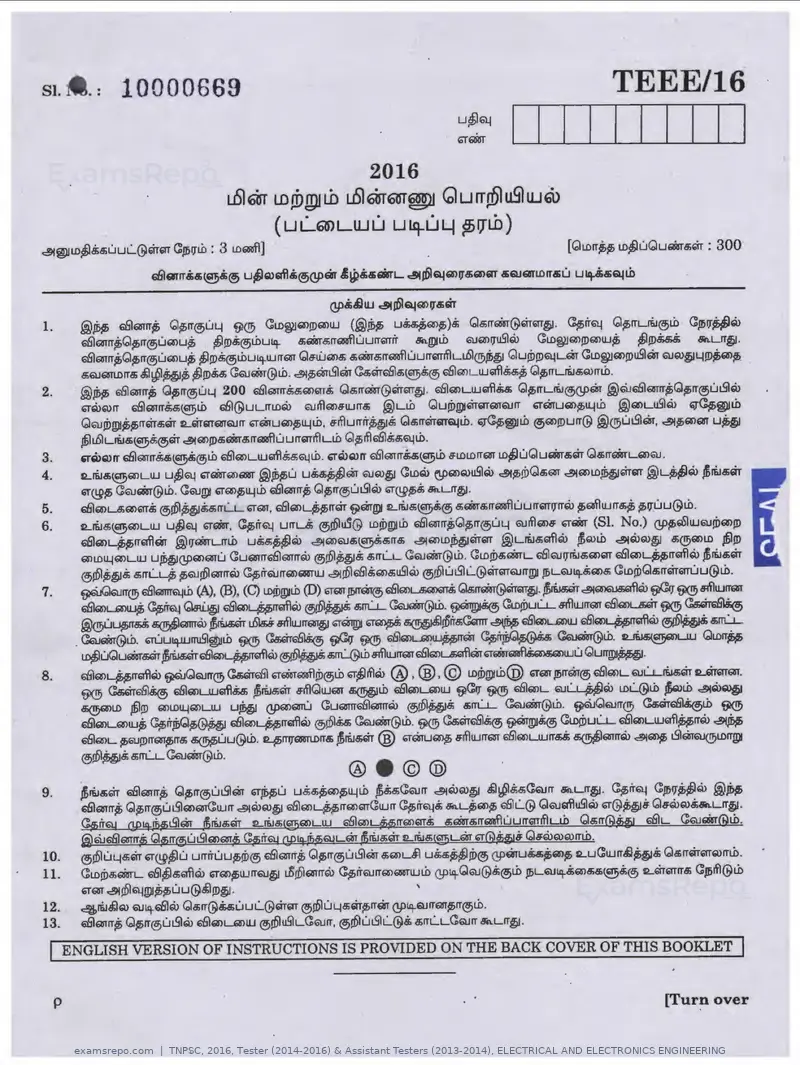
Text of page 2
SPACE FOR ROUGH WORK   ' f

                                            •
II


     TEEE/16           2                        p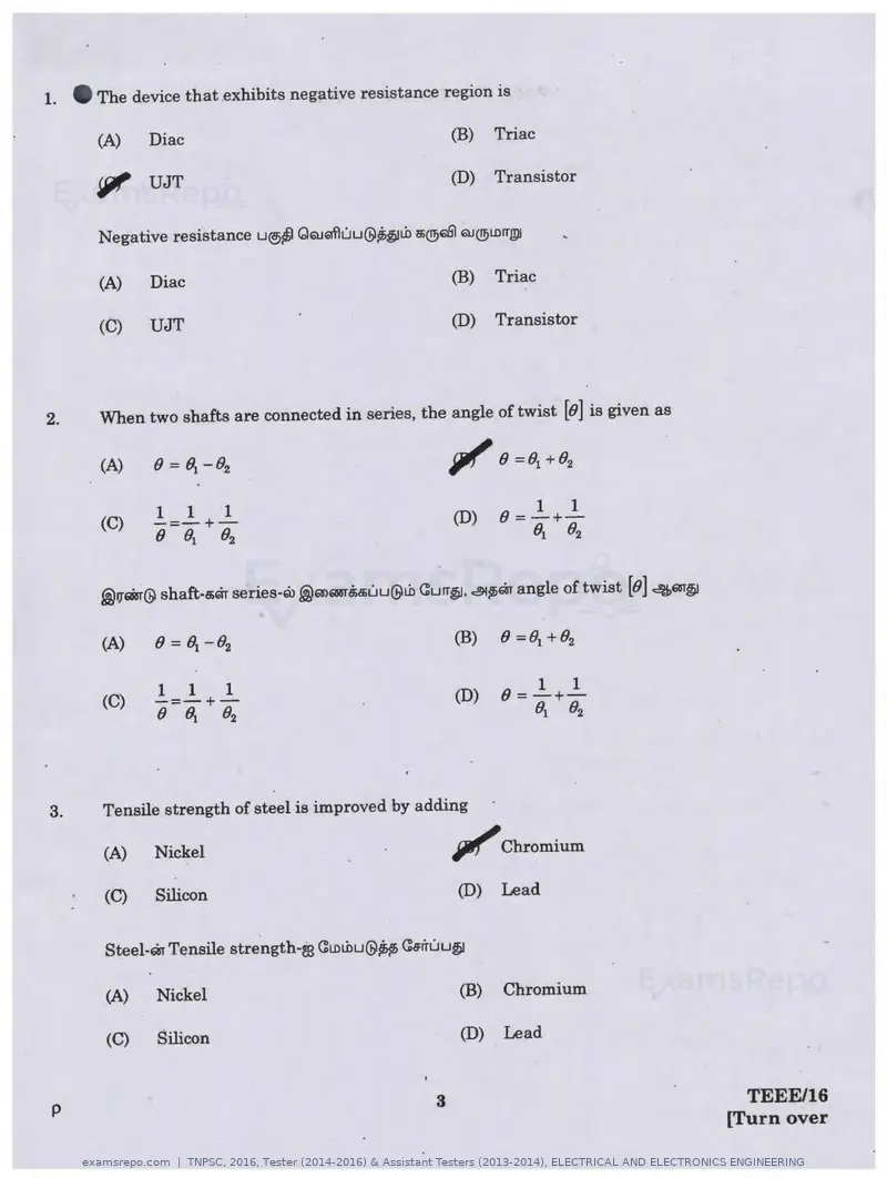
Text of page 3
1. •The device that exhibits negative resistance region is

      (A)    Diac                                         (B)   Triac

      il'f UJT                                           (D)    Transistor


      Negative resistance LI®~ QQJQf'luu@~~Lh !iQ96lS! QJQ!)LDITJ!)I

      (A)    Diac                                        (B)    Triac

      (C)    UJT                                         (D)    Transistor


2.    When two shafts are connected in series, the angle of twist [8] is given as

                                                         " ' 8 =81 +82


      (C)                                                (D)


      ®v•@ shaft-a;Gilr series-ro .@mQm'uuu@Lh Curr~. ~p;ar angle of twist [8] ~m~


      (A)                                                (B)

             1    1    1                                               1   1
      (C)    -=-+-                                       (D)    8=-+-
             8   Bi   82                                          o. 82


3.   Tensile strength of steel is improved by adding

     (A)    Nickel                                       jtf1"Chromium
     (C)    Silicon                                      (D)    Lead


     Steel-ar Tensile strength-re CLDLhu@~ Ca:iruu~

     (A)    Nickel                                       (B)    Chromium

     (C)    Silicon                                      (D)    Lead


p                                                    3                                 TEEE/16
                                                                                     [Turn over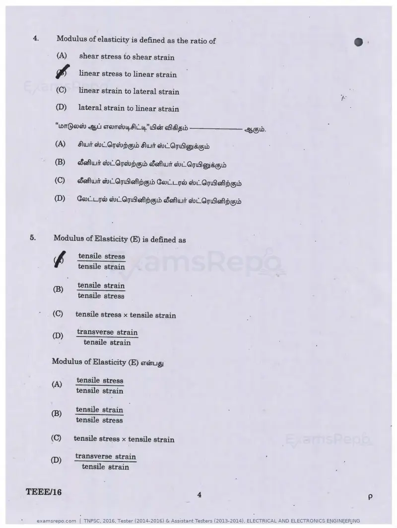
Text of page 4
4.   Modulus of elasticity is defined as the ratio of

     (A)   shear stress to shear strain
                                                                                    •
     ~     linear stress to linear strain

     (C)   linear strain to lateral strain                                   i···
     (D)   lateral strain to linear strain


     (C)    ~MlUJir wi.:..G11u5lM1Ji>®t.b C:Q)LL-11Q> wL..G11u5lMl!f>®t.b

     (D)   (:Q)L..L11Q> wi.:..Q11u5l'8fl!D®t.b ~MlUJir wL..G11u5lM1Ji>®t.b


5.   Modulus of Elasticity (E) is defined as

            tensile stress
     <I     tensile strain

            tensile strain
     (B)
            tensile stress

     (C)    tensile stress x tensile strain

            transverse strain
     (D)
              tensile strain

     Modulus of Elasticity (E) '1"6Bru~

            tensile stress
     (A)
            tensile strain

            tensile strain
     (B)
            tensile stress

     (C)    tensile stress x tensile strain

            transverse strain
     (D)
              tensile strain


TEEE/16                                                    4                            p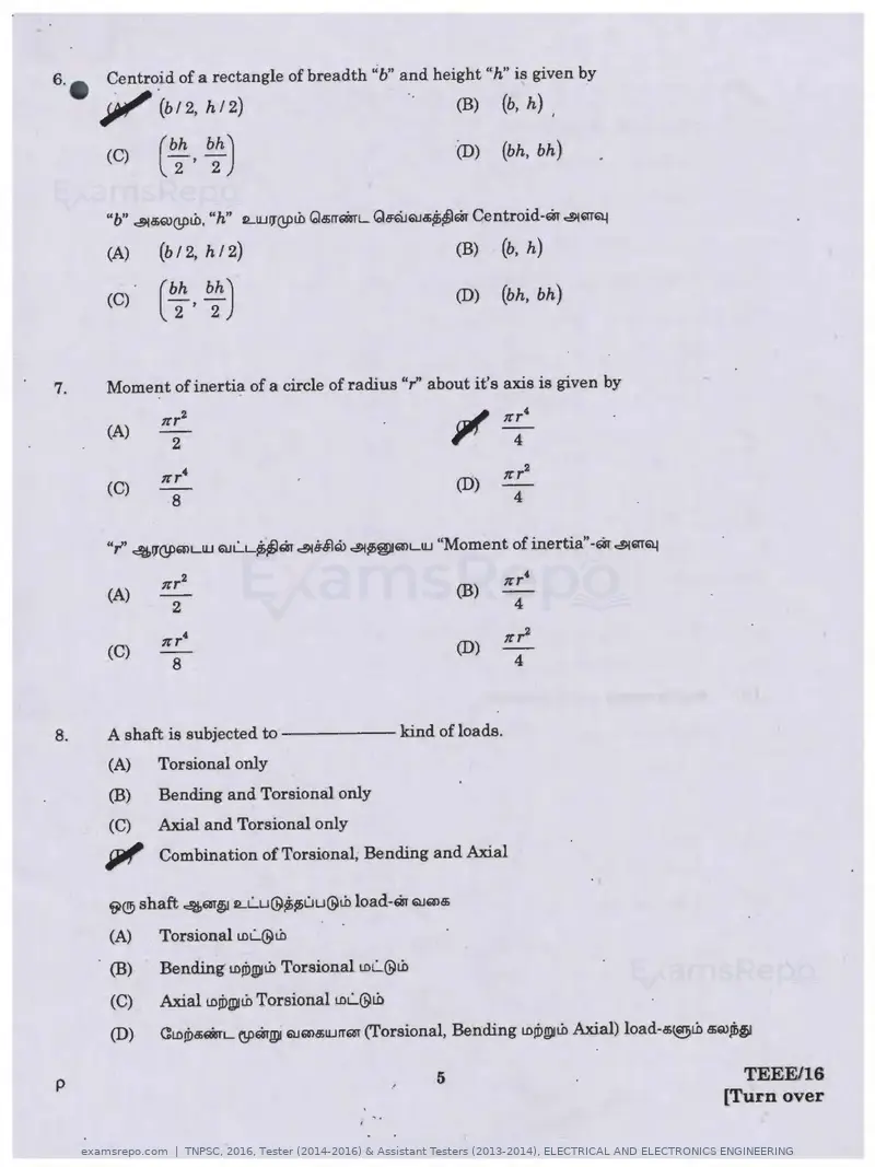
Text of page 5
6. ;JI!"'
      Centro.id of a rectangle of breadth " b" a_n d height "h" is given by
             (b12, h12)                               .       (B)   (b, h) ,

      (C)    (b;' b:)                                         (D)   (bh, bh)


      (A)    (bf 2, hf 2)                                     (B)   (b, h)

      (C)     bh bh)                                          (D)   (bh, bh)
             ( 2 , 2


7.   Moment of inertia of a circle of radius "r' about it's axis is given by

     (A)
               2                                                     4

                                                                    nr2
     (C)                                                      (D)
               8                                                     4


                                                              (B)
                                                                    nr'
     (A)
              2                                                      4

     (C)
             trr4
                                                              (D)
                                                                    nr2
               8                                                     4


8.   A shaft is subjected t o - - - - - kind of loads.
     (A)    Torsional only
     (B)    Bending and Torsional only
     (C)    Axial and Torsional only
     iJI/' Combination of Torsional, Bending and Axial
     ~®shaft 4m~ rLL..u@~~uu@t.h load-m QJQ)a;

     (A)    Torsional tDL..@t.h

     (B)    Bending tD!i:>g»t.i> Torsional LDL.@L.b

     (C)    Axial t0d:>I!)IL.b Torsional t0L..@ili
     (D)    C:LD!i:>a>fiilrL (!P'1lgv QJQ)a;UJrrm (Torsional, Bending LD!f>g)lt.h Axial) load-a;~L.b 5Q)~

p                                                         5                                           TEEE/16
                                                                                                    [Turn over
Text of page 11
24·_ •   In a Synchronous motor damper winding is provided in order to
         (A)    Stabilise rotor rotation
         (B)    Suppress rotor oscillations
         (C)    Develop necessary starting torque
         ~ Both (B) and (C)


         (A)    C:1Jrn:..urfr e;~!DelQ>UJ .ffil6J>ruuu@~fb

         (B)    ·a1JrrL.Lrrfr c:!ib6laQ)~m61'l61U ®6J>!DUUfb!D®


25.      The full load voltage regulation of an alternator is -2%. This indicates that the load power
         factor is
         (A)    unity                                             (B)   lagging

         (C)    either unity or lagging                           JJJ" leading
         AC tblmmrrAi.$l uSl~ (Alternator) full load voltage regulation - 2% GiTmu~ load power factor
         ------6rmU6fltb ®ibl~!D~ ·

         (A)    unity                                             (B)   lagging

         (C)    either unity or lagging                           (D)   leading


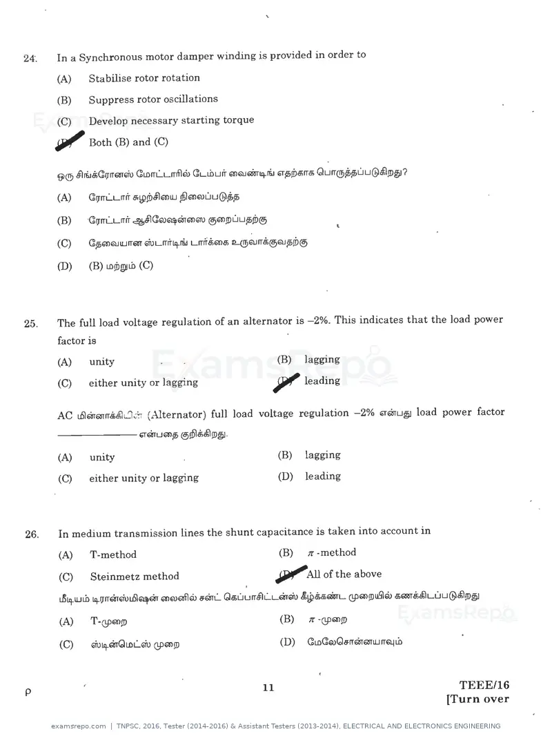
26.      In medium transmission lines the shunt capacitance is taken into account in
         (A)    T-method                                          (B)    n -method

         (C)    Steinmetz method                                  .JJJlf"All of the above

         (A)    T-@Q>!D                                           (B)    tr ·@Q>!f)

         (C)    Giu1ij-m<d1DL.Giu @61l!D                          (D)   aLDaQ)Q~mmmUJITQjtD


p                                                            11                                 TEEE/16
                                                                                              [Turn over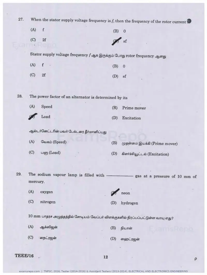
Text of page 12
27.   When the stator supply voltage frequency is f, then the frequency of the rotor current.

      (A)     f                                               (B)   0

      (C)     2f                                              ,r    sf


      Stator supply voltage frequency f 4a; @®8i@>tb Gurr~ rotor frequency 4m~

      (A)    f                                                (B)   0

      (C)    2f                                               (D)   sf


28.   The power factor of an alternator is determined by its

      (A)     Speed                                           (B)   Prime mover

      ,r      Load                                            (D)   Excitation


      4Q>urCan.:...ufl6in uQJrr C:u.tu;1>1J •rrtnrraflu u~

      (A)     (:QJa;tb (Speed)                                (B)   @~mQ)to@w.$.$1 (Prime mover)


      (C)     u~(Load)                                        (D)   .$lQTrrff1~L..L"1> (Excitation)


29.   The sodium vapour lamp is filled with - - - - - - gas at a pressure of 10 mm of
      mercury.

      (A)     oxygen                                          rjl/' neon
      (C)     nitrogen                                        (D)   hydrogen


      (A)     4.$'1\Sl~m                                      (B)   sbJ w rrm

      (C)     mp;L..11~m                                      (D)   '1>~L..11~6in


TEEE/16                                                  12                                           p
Text of page 14
33.   Induction instruments have found widest applications as
      ~ Watt hour meter
      (C)    Ammeter
                                                         (B)

                                                         (D)
                                                                Voltmeter
                                                                Frequency meter
                                                                                                          •
      Induction ~!DfDmQ) Qe:;rr~© Qa:tUruu@tb s;Q?61SltUrr~~ gp;~ 61.Jm&lUrTQT illl....Lrflru ~~a; uUJQ1urr@&mm
      Qe:;rr~@rom@

      (A)    Watt hour meter                             (B)   Voltmeter
      (C)    Ammeter                                     (D)   Frequency meter


34.   The major cause for creeping is
      (A)    Lighting load
      (B)    Capacitive load
      <I'    Over compensation for friction
      (D)    Over load compensation


      (A)    Lighting load
      (B)    Capacitive load
      (C)    Over compensation for friction
      (D)    Over load compensation


35.   The power consumption of PMMC instrument is typically about
      (A~   0.25 W to 2 W
      ~     25 Micro watt to 200 micro watt
      (C)   2.5 milli watt to 20 milli watt
      (D)   0.25 milli watt to 200 milli watt

      PMMC B>Q?6ti1uSla-r power consumption c!l!>~@
      (A)   0.25Wto2W
      (B)   25 Micro watt to 200 micro watt
      (C)   2.5 milli watt to 20 milli watt
      (D)   0.25 milli watt to 200 milliwatt

TEEE/16                                             14                                                       p
Text of page 15
•·    According to safety, the resistance of earthing electrode should be

      ~Low
      (C)    High
                                                         (B)
                                                         (D)
                                                                 Medium
                                                                 Does not affect


      (A)    ®m!D6l.!

      (C)    ~~a;tb     '


37.   If the insulation between two conductors is faulty, a current flows between them. This is
      called as
      (A)    Open circuit fault                          jlll' Short circuit fault
      (C)    Ground fault                                (D)   Cable fault

      @'lar@ BiL~~a;<©.$.$1md:UJ Lmm insulation u~,,mLJi;~ . ~p>@lm t.6lm<:mrn.:...Ltb urni.JQJ,,!i>@>
      - - - - - 6rWI!)J GuUJrr.

      (A)   Open circuit fault                           (B)   Short circuit fault

      (C)   Ground fault                                 (D)   Cable fault


38.   fluid friction damping can be used in

      (A)   Horizontally mounted instruments

      ~Vertically mounted instruments
      '
      (C)   Both vertical and horizontal instruments

      (D)   Plane surface instruments

      Fluid friction damping ~m~ 6r.ffip> B>@QS'luSlru uUJmu@~uu@&l.ro~

      (A)   u@Bima; @mniuS'lru ~mLD.ffi~mm B><!!JQS'I

      (B)   G6ffil®~,,rra; Q)QJ~~mm a;®QS'I

      (C)   u@.$ma; LDWg)ILD G6ffil®~ @mJDuS'lru Liirm B>®QS'I

      (D)   6LDUl]ULS1Q) Q>QJ~~mm 8>(!9661


p                                                   15                                    TEEE/16
                                                                                        [Turn over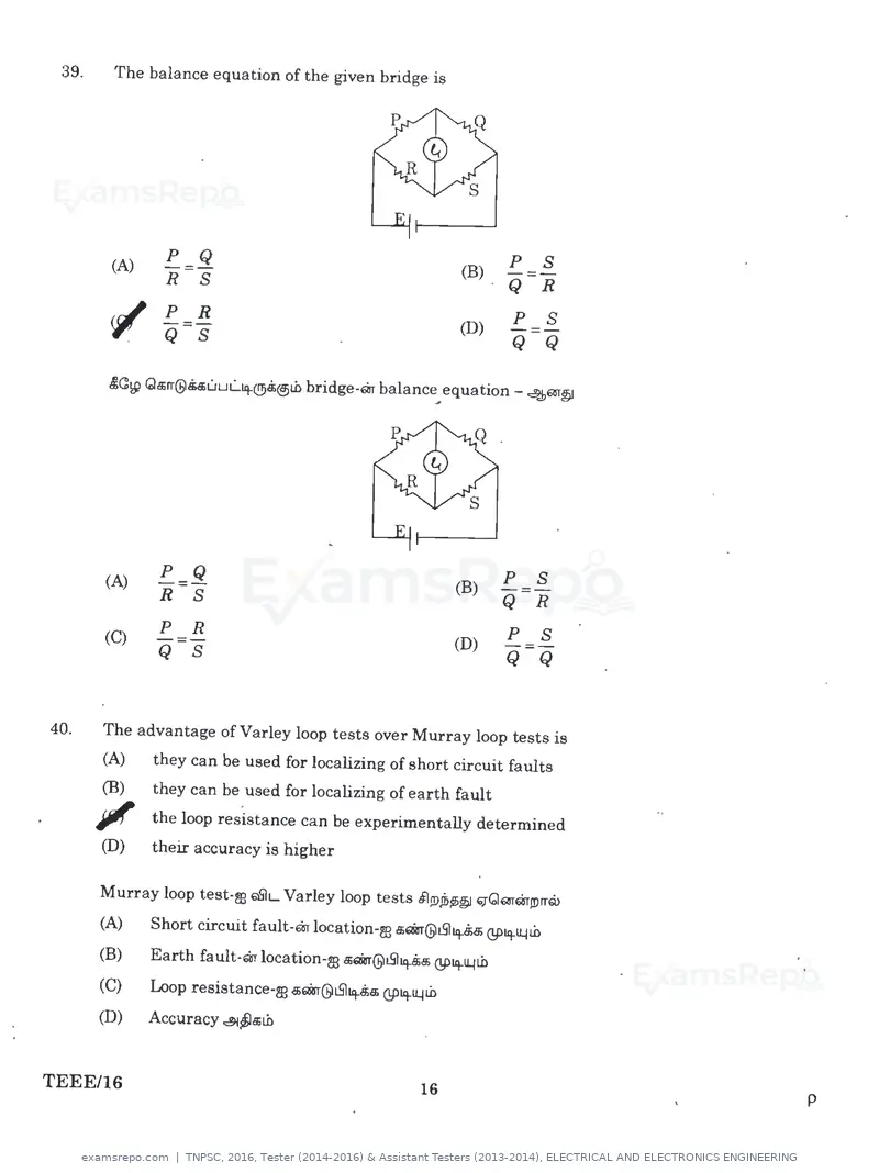
Text of page 16
39.   The balance equation of the given bridge is
                                                                                •
      (A)
             p
             -=-
                   Q                                           (B)
                                                                        p
                                                                        -=-
                                                                            s
             R     s                                                    Q   R
                                                                            s
      ~ Q s
             p R                                                        p
             -=-                                               (D)      -=-
                                                                        Q Q

      £C:w Qa;rr@.5.suuL.iq.@&@>Lb bridge-Q1 balance equation - 4m§J
                                                          ..


      (A)
             p Q
             -=-                                               (B)
                                                                        p
                                                                        -=-
                                                                            s
             R     s                                                    Q R
             p     R                                                    p s
      (C)    -=-                                               (D)      -=-
             Q     s                                                    Q Q


40.   The advantage of Varley loop tests over Murray loop tests is
      (A)    they can be used for localizing of short circuit faults
      (B)    they can be used for localizing of earth fault
      ~      the loop resistance can be experimentally determined
      (D)    their accuracy is higher

      Murray loop test-m "61L Varley loop tests filJDJi>~§I ~QmQ11Drrw
      (A)    Short circuit fault-Q1 location-m a;'*r@t.Sl~ @tq.lJ..11.b
      (B)    Earth fault-Q1 location-m a;'*r@t.Sliq.5.5 QPtq.lJ..11.b
      (C)    Loop resistance-m a;'*r@t.Sl~a; @tq.lJ..11.b
      (D)    Accuracy ~~a;Lb


TEEE/16                                                   16                    p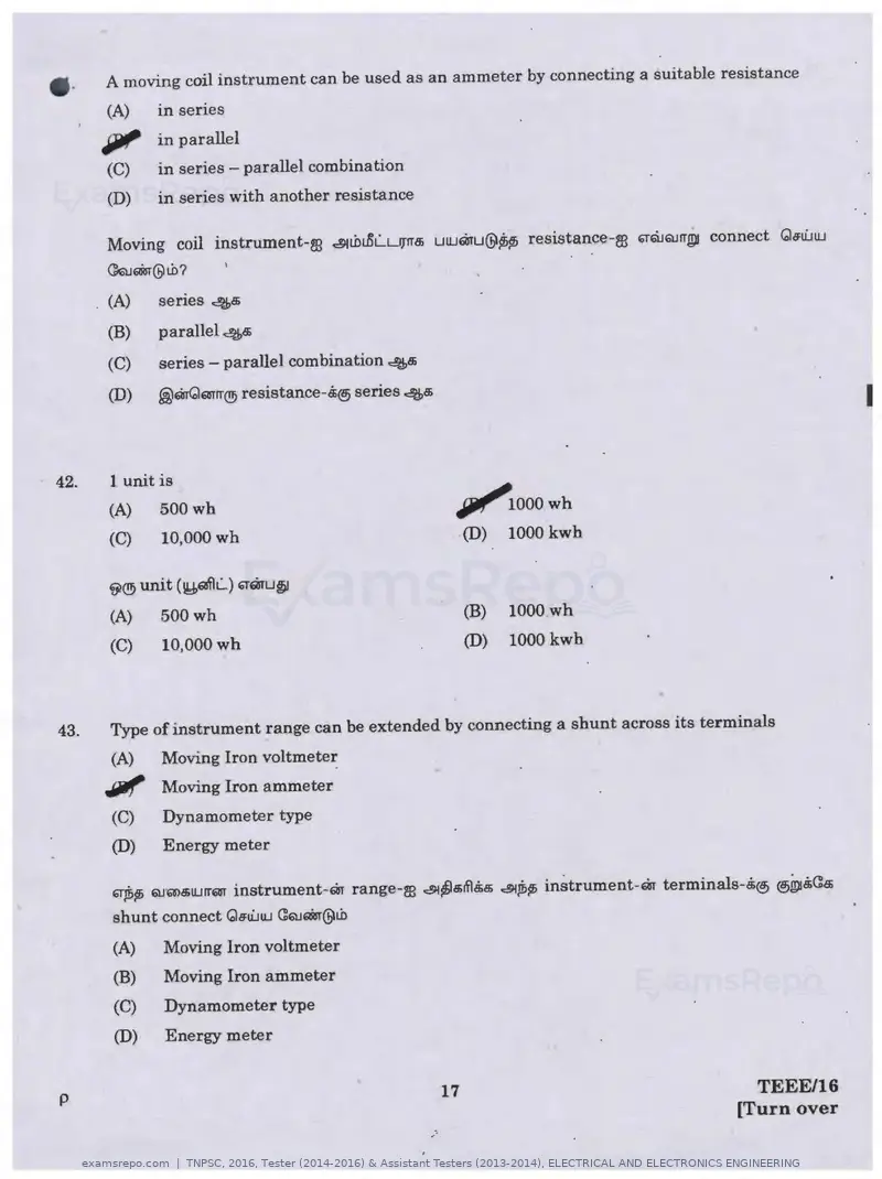
Text of page 17
•·     A moving coil instrument can be used as an ammeter by connecting a suitable resistance
       (A)    in series
      IJJll" in parallel
       (C)    in series - parallel combination
       (D)    in series with another resistance

       Moving coil instrument-m ~tbu5l....LIJ"IT6:i uUJQ1'u@~~ resistance-re ~6i.JGtJrrgii connect Gs:u'..JUJ
       QQJQiar@tb?

       (A)    senes 4e;
       (B)    parallel 46:i
       (C)    series - parallel combination 4e;
       (D)    .@mGmrr(!!i resistance-5@ series 4e;
                                                                                                                I

42.    l unit is
      (A)     500wh                                          IJlll"'iooo wh
      (C)     10,000wh                                       (D)   1000 kwh

      ~(!!i unit (\Y,aflL) ~QrU~

      (A)    500wh                                           (B)   1000 wh
      (C)     10,000 wh                                      (D)   1000 kwh


43.   Type of instrument range can be extended by connecting a shunt across its terminals
      (A)    Moving Iron voltmeter
      Jlllf Moving Iron ammeter
      (C)    Dynamometer type
      (D)    Energy meter

      ~11,, QJQ>B>UJrrm instrument-m range-re ~~e;ITl.$e; ~]1p; inStrument-m terminals-.$® ®~&Ca;
      shunt connect Qs:u'..JUJ (:QJQiar@tb
      (A)    Moving Iron voltmeter
      (B)    Moving Iron ammeter
      (C)    Dynamometer type
      (D)    Energy meter


p                                                       17                                      TEEE/16
                                                                                              [Turn over
                                                   ,·
Text of page 19
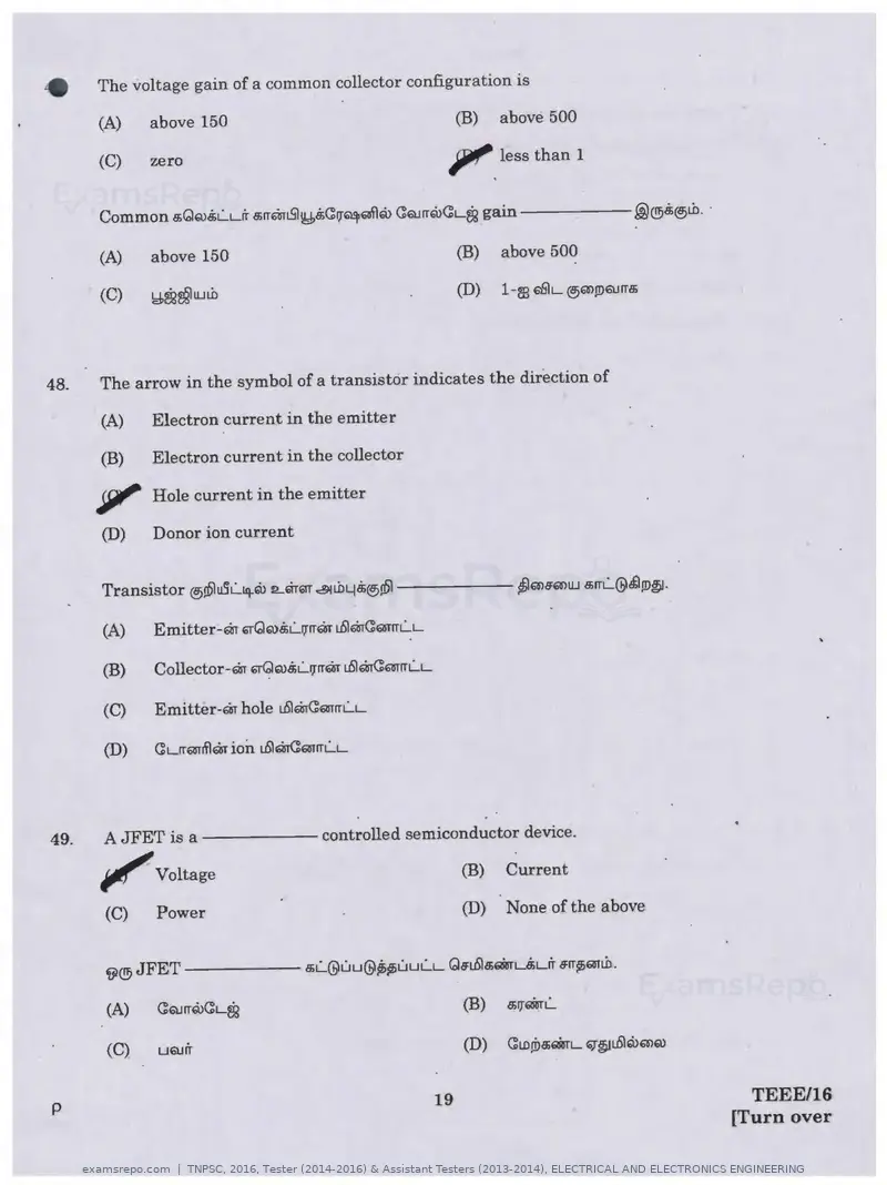
•      The voltage gain of a common collector configuration is

       (A)   above 150                                         (B)   above 500

       (C)   zero                                              ?'.   less than 1


       (A)   above 150                                         (B)   above 500


48.   The arrow in the symbol of a transistor indicates the direction of

      (A)    Electron current in the emitter

      (B)    Electron current in the collector

      , . Hole current in the emitter

      (D)    Donor ion current


      (A)    Emitter-m gQro.iL....rrrrm uSlmC:wrrl....L

      (B)    Collector-m 6Tu?ro8;L....17rrm uSl~Q!TITLL

      (C)    Emitter-m hole uSl~mrrl....L


49.   AJFET is a - -----controlled semiconductor device.

      ~Voltage                                                 (B)   Current

      (C)    Power                                             (D)   None of the above


      ~®JFET

      (A)    ~QJITQl(:L~


      (C)    U6Urr


p                                                         19                               TEEE/16
                                                                                         [Turn over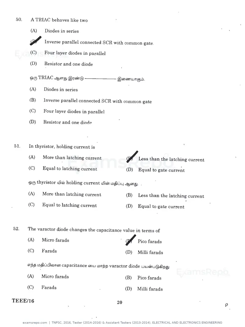
Text of page 20
50.   A TRIAC behaves like two

      (A)    Diodes in series
                                                                                                 •
      ~ Inverse parallel connected SCR with common gate.
      (C)    Four layer diodes in parallel

      (D)    Resistor and one diode


      (A)    Diodes in series

      (B)    Inverse parallel connected SCR with common gate

      (C)    Four layer diodes in parallel

      (D)    Resistor and one diode


51.   In thyristor, holding current is

      (A)    More than latching current                   "Less than the latching current
                                                                                   .
      (C)    Equal to latching current                    (D)   Equal to gate current

      VI® thyristor uSlQ> holding current uSlQi LD/JuLJ 46al~ . .

      (A)    More than latching current                   (B)   Less than the latching current

      (C)    Equal to latching current                    (D)   Equal to gate current


52.   The varactor diode changes the capacitance value in terms of

      (A)    Micro farads                                 ~ Pico farads
      (C)    Farads                                       (D)   Milli farads

      "'Jbf> LDjJutSlQ>rrQT capacitance a>UJ LDITJD!D varactor diode utUmu@£ln>~
      (A)    Micro farads                                 (B)   Pico farads

      (C)    Farads                                       (D)   Milli farads

TEEE/16                                              20                                          p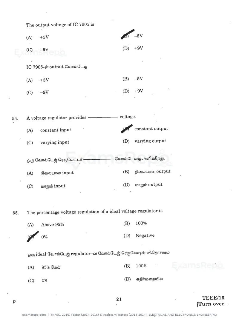
Text of page 21
If.   The output voltage of IC 7905 is

      (A)   +5V                                   /-5V

      (C)   -9V                                      (D)   +9V


      IC 7905-Qr output (]QJrrruC:L~

      (A)   +5V                                      (B)   -5V

      (C)   -9V                                      (D)   +9V


54.   A voltage regulator provides----- voltage.

      (A)   constant input                        Jlllf' constant output
      (C)   varying input                            (D)   varying output


      (A)   ~Q>Q>IUITQT input                        (B)   ~Q>Q>U.JITQT output


      (C)    tnrrglll.b input                        (D)   LDITJl')ILD   output


55.   The percentage voltage regulation of a ideal voltage regulator is

      (A)    Above 95%                               (B)   100%


      , , 0%                                         (D)   Negative


      (A)    95% C:tnru                              (B)   100%


      (C)    0%


                                                21                                  TEEE/16
p
                                                                                  [Turn over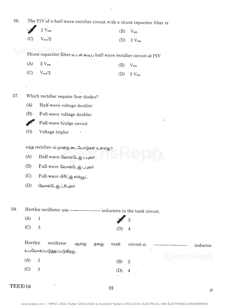
Text of page 22
56.   The PIY of a half-wave rectifier circuit with a shunt capacitor filter is

      ~ 2 Yam                                                (B)   Vsm
                                                                                        •
      (C)   Ysm/2                                            (D)   3 Yam


      Shunt capacitor filter-:LLm Bil.~lLI half-wave rectifier circuit-m PIY

      (A)    2 Yam                                           (B)   Vem
      (C)   Vsm/2                                            (D)   3 Yam


57.   Which rectifier require four diodes?
      (A)   Half-wave voltage doubler
      (B)   Full-wave voltage doubler
      '11' Full-wave bridge circuit
      (D)   Voltage tripler


      (A)   Half-wave CQJrrQ>Cq~ L4mfr

      (B)    Full-wave ~rrlii>CL~ L4'1Tfr

      (C)    Full-wave ~~L.m 11rr.9il!J>L...

      (D)    CQJrrlii>CLSi L...ifl461Tr'r


58.   Hartley oscillator use - - - - - - inductors in the tank circuit.

      (A)    1                                               ~2
      (C)    3                                               (D)   4


      Hartley       oscillator          4m~    ~601"~   tank       circuit-Gil    inductor
      :Lu(]UJrre;uu@~uu@~JD~·

      (A)    1                                               (B)   2
      (C)    3                                               (D)   4


TEEE/16                                                 22                               p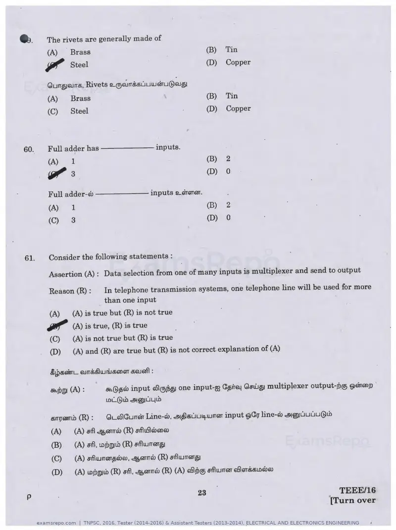
Text of page 23
••    The rivets are generally made of
      (A)       Brass                                                (B)    Tin
      Jli1I' Steel                                                   (D)    Copper

      Qurr~6l.HT8i, Rivets t2...(!9~ rr.$a;uuUJmu@QJ~
      (A)       Brass                                                (B)    Tin
      (C)       Steel                                                (D)    Copper


60.   Full adder has                             inputs.
      (A)       1                                                   (B)     2

      wt' 3                                                         (D)     0

      Full adder-Qi                           inputs lLGTQTQJ.
      (A)       1                                                   (B)     2
      (C)       3                                                   (D)     0


61.   Consider the following statements :

      Assertion (A) : Data selection from one of many inputs is multiplexer and send to output

      Reason (R) :         In telephone transmission systems, one telephone line will be used for more
                           than one input
      (A)      (A) is true but (R) is not true


      """
               (A) is true, (R) is true
      (C)      (A) is not true but (R) is true
      (D)      (A) and (R) are true but (R) is not correct explanation of (A)


      Sil.Ii>~ (A) :       Bn@$firu input '°1®Ji>~ one input-re C$firl"Q! Qsti.J~ multiplexer output-ti>® ~moow
                           tnL...@Lb ~~u4Lb

      e;rr11QRJTLb (R) :   GL'°1Currm Line-ru, ~~e;Liu11tUJITQT input ~C11 line-ru ~~uuuu@Lb
      (A)      (A) srfl 46l1Trrru (R) sifluSlQ)Q>Q)
      (B)      (A) s:tfl. LDW!PltD (R) s:rflUJITQJ~
      (C)      (A) s:rflUJrrm$liQ>Q), 46l1Trrru (R) a:tflUJrrQJ~
      (D)      (A) LDW!PJLD (R) s:rfl. 46l1Trrru (R) (A) 6'61!i>® s:rflUJrrQJ E>@QT.$a;LDQ)Q)

p                                                              23                                  TEEE/16
                                                                                                 [Turn over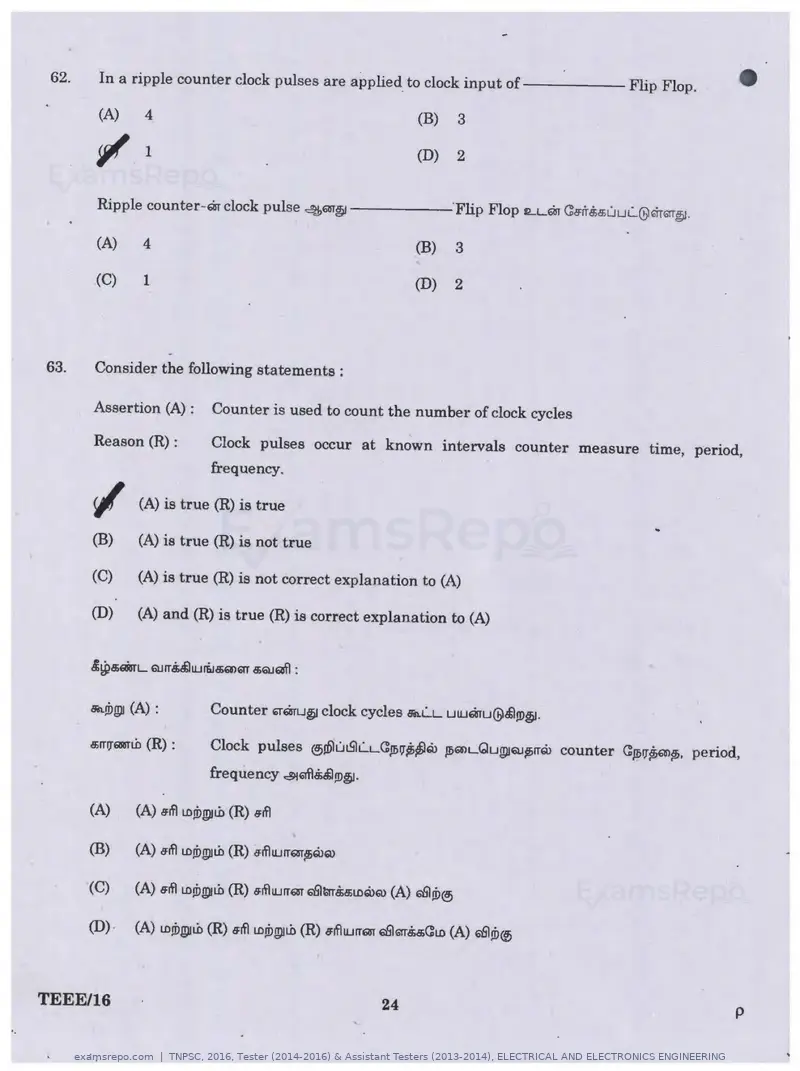
Text of page 24
62.   In a ripple counter clock pulses are applied to clock input o f - - - - - Flip Flop.

           (A)       4                                             (B)   3
                                                                                                                       •
           ~ 1                                                     (D)   2


           Ripple counter-ar clock pulse ~611~                           'Flip Flop ILL~ a<'frr8;c$ULJLQ;lITTG!T~.

           (A)       4                                             (B)   3

           (C)       1                                             (D)   2


     63.   Consider the following statements :

           Assertion (A) :        Counter is used to count the number of clock cycles

           Reason (R) :           Clock pulses occur at known intervals counter measure time, period,
                                  frequency.

           </        (A) is true (R) is true

           (B)       (A) is true (R) is not true

           (C)       (A) is true (R) is not correct explanation to (A)

           (D)       (A) and (R) is true (R) is correct explanation to (A)


           BA.Wgll (A) :          Counter '1'QrW~ clock cycles Bft.LL u1Uaru@.$l!D~ ·

           s;rr11lillln.b (R) :   Clock pulses ®Jb'lutSIL...LC:,(li'l~~Q) ,(liQlLGUg)IQJ~fTQ} counter a,!lilJ'~~· period,
                                  frequency ~Qfl.i&l!D~·


     TEEE/16                                                  24                                                        p
..
Text of page 27
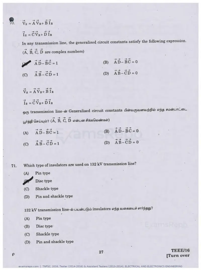
-+         -+ -+         -+ -+
       Vs=AVR + Bla
       -+         -+ -+        -+ -+
       Is =CVR + Dla

      In any transmission line, the generaliseq circuit constants satisfy the following expression.
        -+   -+     -+    -+
       (A, B, C, D are complex numbers)

                   -+ -+       -+-+                                   -+ -+   -+-+
                   AD-BC=l                                      (B)   AD-BC=O
                   -+ -+       -+ -+                                  -+ -+   -+ -+
       (C)         AB-CD=l                                      (D)   AB-CD= 0


       -+         -+ -+        -+-+
       Vs=AVR + Bh
       -+     -+-+             -+-+
       Is= CVa+ D Ia

      ij)@ transmission line-m Generalisec!. circuit constants t5lmQJ@QJWQJ!i>J61"1> "J~~ B'lL>murrL..Q'lL
                                       -+   -+   -+   -+
      ~r'r~ Qa;!Ull..ltb? (A, B, C, D GTQTUQT 51~a;QQ)QiBra;6Tr)

                   -+ -+       -+-+                                   -+ -+   -+-+
      (A)          AD - BC=l                                    (B)   AD-BC= 0
                   -+ -+       -+ -+                                  -+ -+   -+ -+
      (C)          AB - CD=l                                    (D)   AB-CD= 0


71.   Which type of insulators are used on 132 kV transmission line?

      (A)         Pin type

      ~ Disctype
      (C)         Shackle type

      (D)         Pin and shackle type


      132 kV transmission line-Q> utUmu@tb insulators GT,di$6 QJQ'lc$Q'ltU6 .Jrrir~~~?

      (A)         Pin type
      ·(B)        Disc type

      (C)         Shackle type
      (D)         Pin and ·shackle type

p                                                          27                                 TEEE/16
                                                                                           [Turn over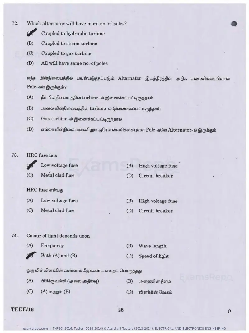
Text of page 28
72.    Which alternator will have more no. of poles?

       ~ Coupled to hydraulic turbine
                                                                                                                          •
       (B)    Coupled to steam turbine
       (C)    Coupled to gas turbine
       (D)    All will have same no. of poles


       ~lb~   L.6lm.@Q)Q)tu~~Q>     utumu@~~uu@lb       Alternator     @tufb~IJ~~Eii>   c:!91~Bi   ~•6Rf!Sims;uS'IQ>rrm

       Pole-s;Q-r .@®Bi®lb?

       (A)    fir L.6lm,miQ)Q)tu~~Qr turbine-Q>@Q>QRITMuuL.~@~tfirrQ>

       (B)    c:!91QTru L.6lm.@Q)Q)tu~~Qi turbine-ru @Q)QRJT.$s;uuL.~fe~rrQ>

       (C)    Gas turbine-ru .@Q)QRIT8;a;uuL..~@~~rrQ>

       (D)    ~ruQ>rr L.6lm.ffilQ'lQ)turi.J.g;'1fl~Lh ~<:11 g~aaf!B;ms;11.4m~ Pole-s;C:QT Alternator-Q> .@®~®Lb


73.    HRC fuse is a

       ~ Low voltage fuse
                   I
                                                              (B)   High voltage fuse
       (C)    Metal clad fuse                                 (D)   Circuit breaker

       HRC fuse ~mu~

       (A)    Low voltage fuse                                (B)   High voltage fuse
       (C)    Metal clad fuse                                 (D)   Circuit breaker


7 4.   Colour of light depends upon
       (A)    Frequency                                       (B)   Wave length

       Jiff Both (A) and (B)                                  (D)   Speed of light


       (C)     (A) LD!i>g)llb (B)


TEEE/16                                                  28                                                           p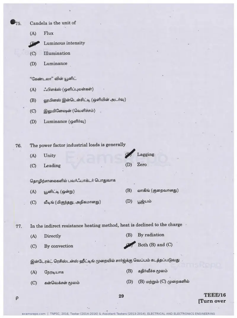
Text of page 29
~5.     Candela is the unit of

        (A)    Flux

       JJJil' Luminous intensity
       (C)     illumination

       (D)     Luminance


       (D)    Luminance {~61flrrQ.l)


 76.   The power factor industrial loads is generally

       (A)    Unity                                     glf Lagging
       (C)    Leading                                   (D)   Zero


       (A)    l!J,Eillfh.:...~ { ~mwi)

       (C)    ~~r&J (L.61®Ji>~. &i~c!DLDITQIT~)         (D)   ~UJl.b


77.    In the indirect resistance heating method, heat is declined to the charge

       (A)    Directly                                  (B)   By radiation

       {C)    By convection                            Jlllf' Both (B) and (C)

       (A)    CJ!il]~UJITc!D


p                                                 29                                 TEEE/16
                                                                                   [Turn over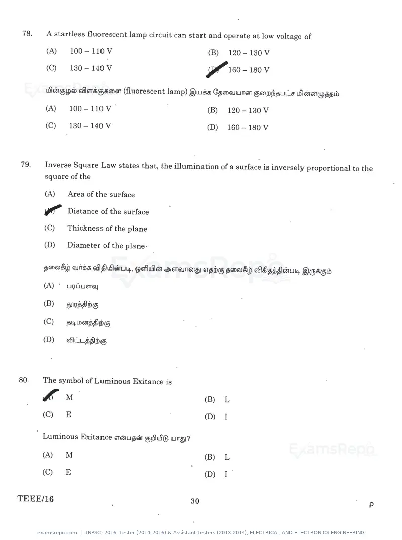
Text of page 30
78.   A startless fluorescent lamp circuit can start and operate at low voltage of

      (A)     100 - 110 V                               (B)   120 - 130 V
                                                                                                   •
      (C)     130 - 140 V                               ? f "160-l80V


      (A)     100 - 110 V                               (B)   120 - 130 v

      (C)     130 -140 V                                (D)   160 - 180 v


79.   Inverse Square Law states that, the illumination of a surface is inversely proportional to the
      square of the

      (A)     Area of the surface

      i/f' Distance of the surface
      (C)     Thickness of the plane

      (D)     Diameter of the plane ·


      (A) '   Ul}"UU'11"Qj


      (B)     ~'l~JD®

      (C)     p;iq.LDmU1!D®

      (D)     6'61LL~JD®


80.   The symbol of Luminous Exitance is

      ~ M                                               (B)   L

      (C)     E                                         (D)   I

      Luminous Exitance '1"mu~6ir ®!6luS@ lUIT§?

      (A)     M                                         (B)   L

      (C)     E                                         (D)   I


TEEE/16                                            30                                                  p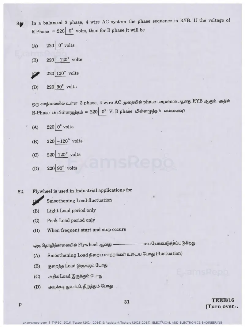
Text of page 31
In a balanced 3 phase, 4 wire AC system the phase sequence is RYB. If the voltage of
        R Phase = 220~ v~lts, then for B phase it will be

        (A)    220~ volts

        (B)    220!-120° volts


        ?      220! 120° volts

        (D)    220 j 90° volts


        f;)® s:LD.@mQ)uSlru lL~HiTT 3 phase, 4 wire AC (!pQ)JDuSlru phase sequence 4681'@ RYB 4@Lb. &r~ru

        R-Phase m t.6lmm-~~~Lb = 220~ V. B phase t.6lmar~~~Lb '1"6\JQJm~?

      . (A)    2201 0° volts

        (B)    2201-120° volts

        (C)    2201120° volts

        (D)    220190° volts


82.     Flywheel is used in Industrial applications for

       ~ S~oothening Load·fluctuation
        (B)   Light Load period only
        (C)   Peak Load period only

        (D)   When frequent start and stop occurs


        (A)   Smoothening Load .@m!DUJ LDrTJDjDr&l&'1r :LQ)LUJ C:urr~ (fluctuation)

        (B)   @)Q>.!D.ffi~ Load ~®.$®Lb C:urr@

        (C)   &r~& Load ~®.$®Lb C:urr@

        (D)   &riq.&'Jiiq.@QJr&i.$1, ~g)J~~Lb C:urr~


p                                                      31                                    TEEE/16
                                                                                           [Turn over .•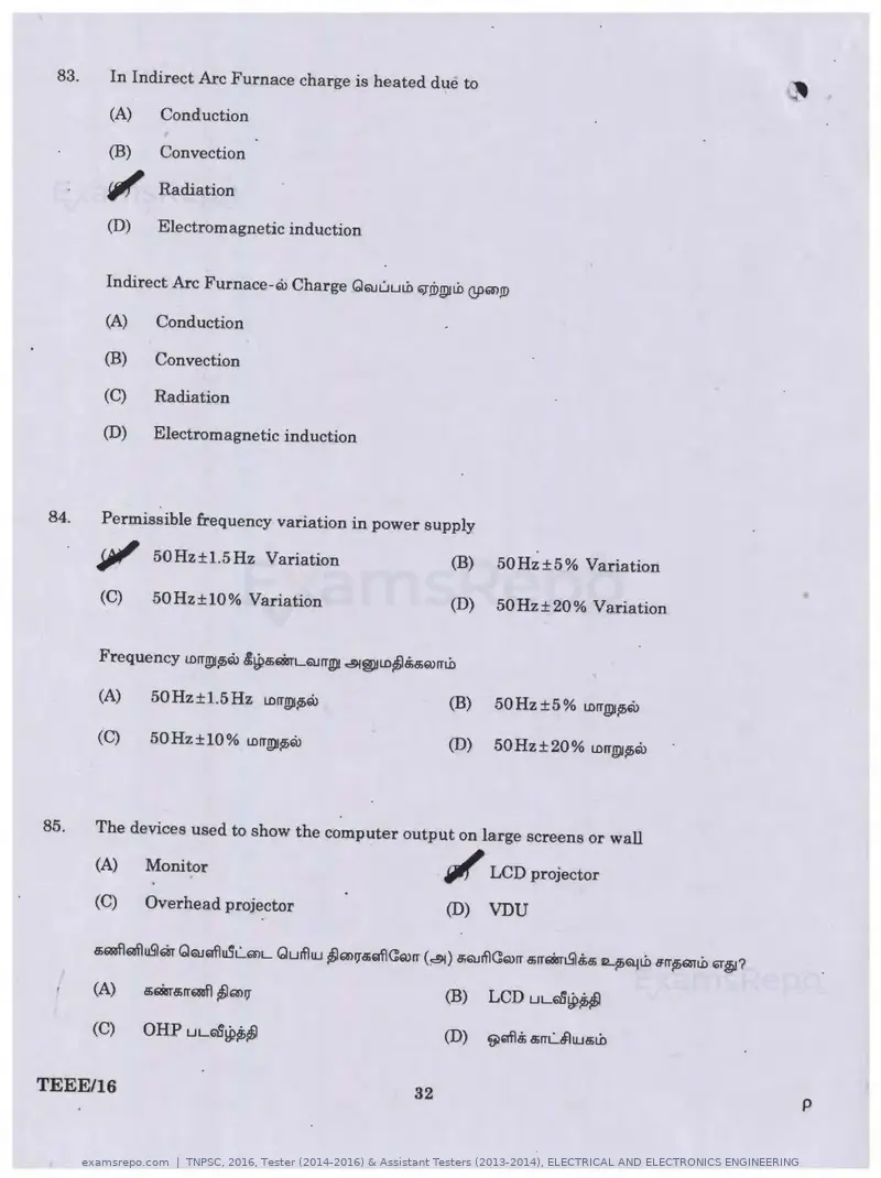
Text of page 32
83.   In Indirect Arc Furnace charge is heated due to

      (A)    Conduction

      (B)    Convection

      W'f Radiation
      (D)    Electromagnetic induction


      Indirect Arc Furnace-ru Charge QQ.Juulb ~!Dg)!Lb (!f>Q'>!D

      (A)    Conduction

      (B)    Convection

      (C)    Radiation

      (D)    Electromagnetic induction


84.   Permissible frequency variation in power supply

      ~ 50Hz±l.5Hz Variation                                (B)   50Hz±5% Variation

      (C)     50Hz±10% Variation                            (D)   50Hz±20% Variation         "


      Frequency lDIT!Dllh'° .l~a;QsrLQJITg)I ~~LD~.!ia;Q)ITLO

      (A)     50Hz±l.5Hz LOIT!Dllh'°                        (B)   50 Hz ± 5 % LDIT@lh'°

      (C)     50Hz±10 % LDIT!Dllh'°                         (D)   50 Hz± 20 % LDIT£tlllh'°


85.   The devices used to show the computer output on large screens or wall

      (A)    Monitor                                        j/Jf LCD projector
      (C)    Overhead projector                             (D)   VDU


                                                            (B)   LCD UL~~~

      (C)    OHP UL~~~


TEEE/16                                                32                                        p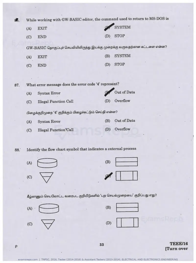
Text of page 33
~-     While working with OW-BASIC editor, the command used to return to MS-DOS is

       (A)    EXIT                                   ~SYSTEM
       (C)    END                                    (D)   STOP


       (A)    EXIT                                   (B)   SYSTEM

       (C)   END                                     (D)   STOP


87.    What error message does the error code '4' represent?

       (A)   Syntax Error                            11'   Out of Data

       (C)   Illegal Function Call                   (D)   Overflow


       (A)   Syntax Error                            (B)   Out of Data

       (C)   Illegal Function"Call                   (D)   Overflow


88."   Identify the flow chart symbol that indicates a external process


       (A)   B                                       (B)   1----tl
       (C)    9                                      ~!~I--. . .I


       (A> · G                                       (B)I- -   ---ti
       (C)    v                                      (D)   l.__._I~II
p                                               33                              TEEE/16
                                                                              [Turn over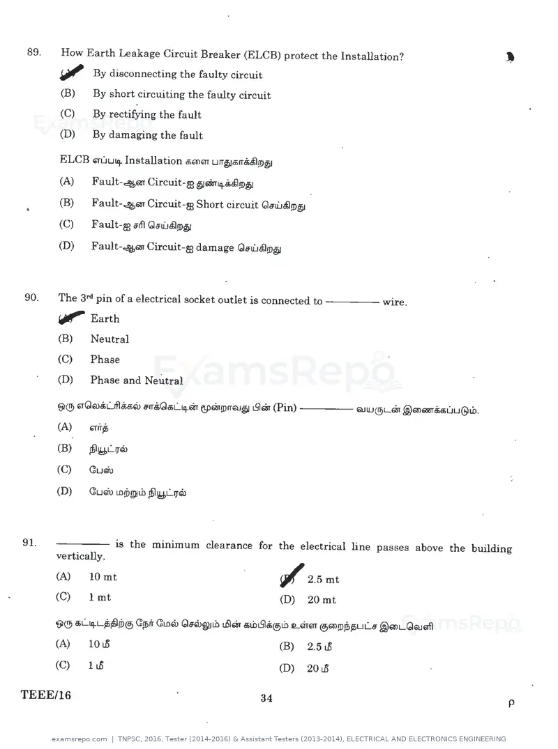
Text of page 34
89.   How Earth Leakage Circuit Breaker (ELCB) protect the Installation?
      IJll' By disconnecting the faulty circuit
      (B)    By short circuiting the faulty circuit
      (C)    By rectifying the fault
      (D)    By damaging the fault

      ELCB 'T'Liuiq. Installation 5'il>QT urr~&rr5&'l!D~
      (A)    Fault-4QI' Circuit-m §1'1Briq.5&'l!D~
      (B)    Fault-4QI' Circuit-m Short circuit GcJu'..i5l!D~
      (C)    Fault-m .Jifl G.Ju'..i5l!D~
      (D)    Fault-4QI' Circuit-ts damage Ga:li.J5l!D~


90.   The 3n1 pin of a electrical socket outlet is connected to - - - - wire.
      "Earth
      (B)    Neutral
      (C)    Phase
      (D)    Phase and Neutral

      tj)@ '1'GQ)5LfilMQ) a:rr.$Q5L.._iq.Qi (!PQr!DITQl§I i5lm (Pin) - - - - QIUJ@Lm .@mQllSl'UUU@LD.

      (A)    'fir~

      (B)    J£l~L.11Q>

      (C)    Guau

      (D)    Guau LD!DwiLI> J£l~LIJQ>


91.                   is the minimum clearance for the electrical line passes above the building
      vertically.
      (A)     10 mt                                         ~ 2.5mt
      (C)     1 mt                                          (D)   20 mt

      ~® 5Llq-LUl!i>e Gp;rr GLOQ> Qc!JQ)~Lb uSlQi .sU>i515ei.O ILQrQT em!DJi>~ULc!J .@mLGQlafl

      (A)     10 I!                                         (B)   2.5 I!
      (C)     1 I!                                          (D)   20 I!

TEEE/16                                                34                                               p
Text of page 37
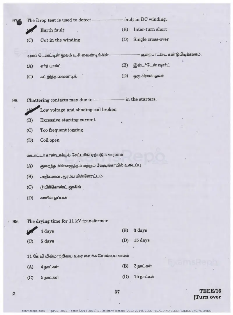
976 The Drop test is used to d e t e c t - - - - - fault in DC winding.

         IJlll'    Earth fault                         (B)   Inter-turn short

          (C)      Cut in the winding                 (D)    Single cross-over


          (A)      f;frr;, urrG>L...


98.       Chattering contacts may due to - - - - - - i n the starters.

         ~Low voltage and shading coil broken
          (B)     Excessive starting current

          (C)     Too frequent jogging

          (D)     Coil open


99.      The drying time for 11 kV transformer

         flll/' days
                  4                                   (B)    3 days

         (C)      5 days                              (D)    15 days


         (A)      4 J!>ITLa;m

         (C)      5 Jl)ITLaiQr                        (D)    15 ,o;rrum


p                                                37                                TEEE/16
                                                                                 [Turn over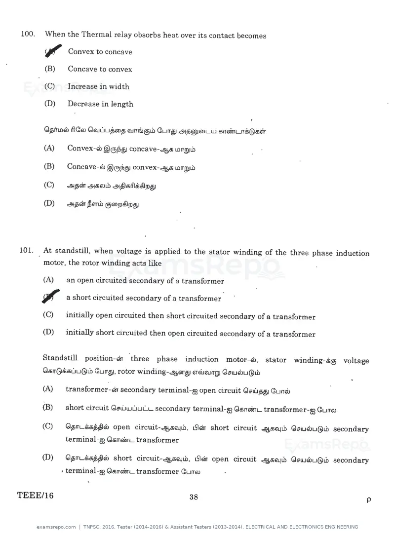
Text of page 38
100.   When the Thermal relay obsorbs heat over its contact becomes

       <jl/' Convex to concave
       (B)   Concave to convex

       (C)   Increase in width

       (D)   Decrease in length


       (A)   Convex-@@®Jb~ concave-4a; LDIT!!)ILO

       (B)   Concave-G>U @®ii>~ convex-~ LDrrgiii.O


101.   At standstill, when voltage is applied to the stator winding of the three phase induction
       motor, the rotor winding acts like

       (A)   an open circuited secondary of a transformer

       ~ a short circuited secondary of a transformer
       (C)   initially open circuited then short circuited secondary of a transformer

       (D)   initially short circuited then open circuited secondary of a transformer


       Standstill position-ar three phase induction motor-@. stator winding-5® voltage
       Qa;rr@8;a;uu@Lh Curr~ . rotor winding-4m~ '1'QJQJITgll Gs:1U@u@Lh

       (A)    transformer-ar secondary terminal-m open circuit Qs:ii.J$D~ <!urrQ>

       (B)    short circuit Qs:u:.i1UuuL.L secondary terminal-m Qa;rrQ8rL transformer-m GurrQ)

       (C)    Q~rrLa;a;p;~@   open circuit-4a;~Lh . t5lar short circuit ~Q.!Lh Qs:iu@u@Lh secondary
              terminal-m Qa;rrQ8rL transformer

       (D)    Q~rrLMp;~Q>     short circuit-4B>Q.1Lh, t5lar open circuit ~Q.lib Gs:1U@u@w secondary
             • terminal-m Qa;rrQ8rL transformer GurrQ)


TEEE/16                                            38                                             p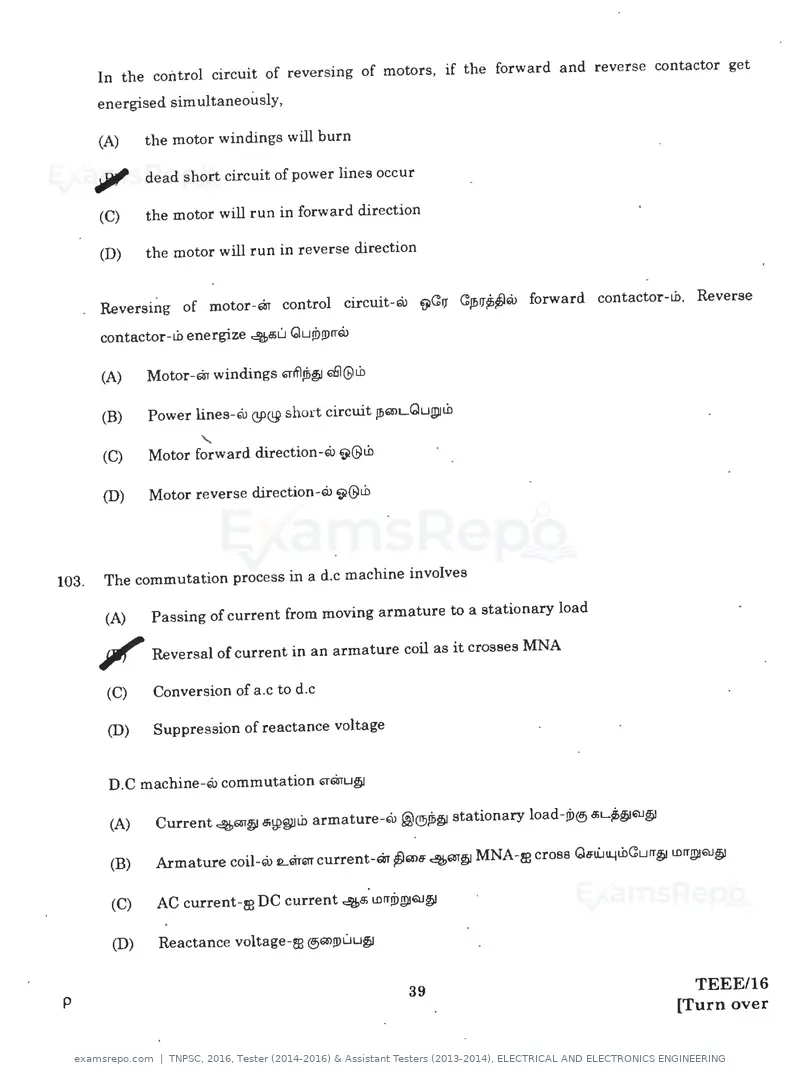
Text of page 39
W· In the control circuit of reversing of motors, if the forward and reverse contactor get
         energised simultaneously,

         (A)    the motor windings will burn

         JJJ' dead short circuit of power lines occur
         (C)    the motor will run in forward direction

         (D)    the motor will run in reverse direction


         Reversing of motor-'8T control circuit-Q> ~C11 CJT>11~'1> forward contactor-Lb, Reverse
         contactor-Lb energize 4a;u <dud.>JDrrG>

         (A)    Motor-ar windings ~ifl,!h§ 66l@Lb

         (B)    Power lines-w QPQ9 short circuit Jf>"'L<duJl)IL.b

         (C)            '
                Motor forward direction-E.i> 9@Lb

         (D)   Motor reverse direction-E.i> 9@Lb


103.     The commutation process in a d.c machine involves

         (A)   Passing of current from moving armature to a stationary load

        ~ Reversal of current in an armature coil as it crosses MNA
         (C)   Conversion of a .c to d.c

         (D)   Suppression of reactance voltage


         D.C machine-w commutation 61"QrU§

         (A)   Current 4m~ c$W~Li> armature-w @@sh§! stationary load-Ji>® 5L~QJ~


         (C)   AC current-~ DC current 45° wrr!i>~QJ§

         (D)   Reactance voltage-m ®"'!DLILI§I


p                                                      39                            TEEE/16
                                                                                   [Turn over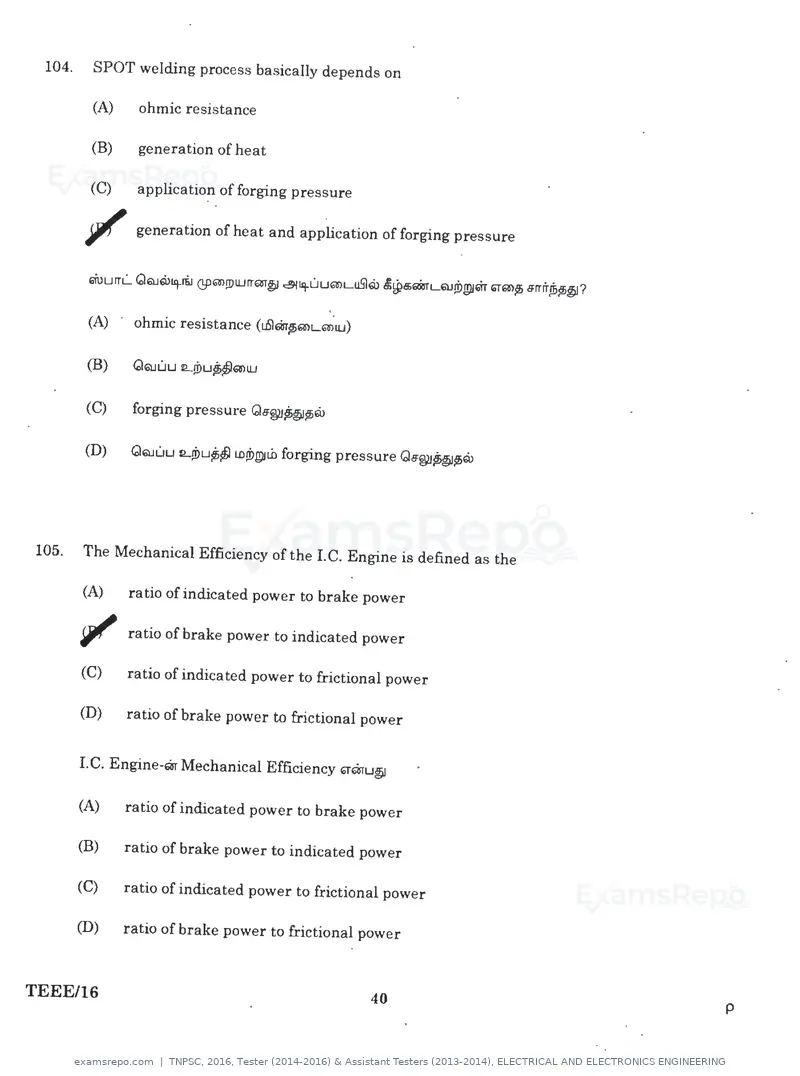
Text of page 40
104.   SPOT welding process basically depends on

       (A)    ohmic resistance

       (B)    generation of heat

       {C)    application of forging pressure

       ?I'    generation of heat and application of forging pressure


,

       (A)    ohmic resistance (i.6lEifrp;Ei11lLGa'>IU)


       (C)    forging pressure Q6§2J~p;Q>


105.   The Mechanical Efficiency of the LC. Engine is defined as the

       (A)    ratio of indicated power to brake power

       1f'I ratio of brake power indicated power
                                         to

       (C)    ratio of indicated power to frictional power

       (D)    ratio of brake power to frictional power


       I. C. Engine-Eiir Mechanical Efficiency '1"Eiiru~

       (A)    ratio of indicated power to brake power

       (B)    ratio of brake power to indicated power

       (C)    ratio of indicated power to frictional power

       (D)    ratio of brake power to frictional power


TEEE/16                                                   40           p
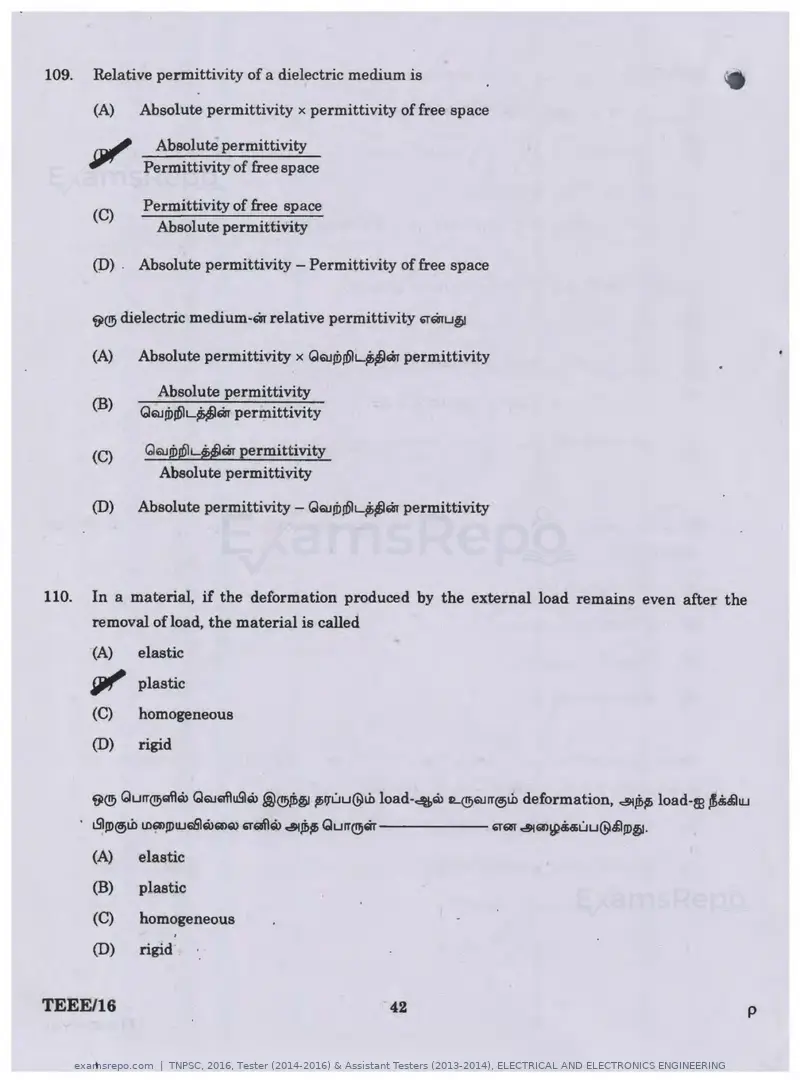
Text of page 42
109.   Relative permittivity of a dielectric medium is

       (A)    Absolute permittivity x permittivity of free space

               Absolute permittivity
              Permittivity of free apace

              Permittivity of free apace
       (C)
               Absolute permittivity

       (D) . Absolute permittivity - Permittivity of free space


       f;}® dielectric medium-m relative permittivity '1''1TU§J

       (A)   Absolute permittivity x QQJd>JDlLU''1T permittivity

                Absolute permittivity
       (B)
              QQJ!i>J61L-U1'1T permittivity

              QQJ!b@L~m permittivity
       (C)
                 Absolute permittivity

       (D)   Absolute permittivity - QQJ!b!DlL$5~m permittivity


110.   In a material, if the deformation produced by the external load remains even after the
       removal of load, the material is called
       (A)    elastic
       SJllf' plastic
       (C)    homogeneous
       (D)    rigid


       (A)    elastic
       (B)    plastic
       (C)    homogeneous
       (D)    rigid


TEEE/16                                            42                                           p
Text of page 43
•·     If the initial tension in the belt drive is increased

       (A)    power transmitted by the belt reduces

       iJI/' power transmitted by the belt increases
       (C)    power transmitted remains same

       (D)    power transmitted have no relation with 'initial tension


       Vl® belt drive-Qi 41Jlbu Tension ~~a;;LDrra;; .@®.d;~rrQ>

       (A)    Belt transmitG11ti.J14tb~IDGlr@)'1>1D.li;~'6l@tb

       (B)    Belt transmit Ge:iU11.jtb f)IJ)m ~~a;;ifl.!;@)tb


112.   For a constant velocity ratio positive drive with large centre distance between driver and
       driven shaft

       (A)    Gear drive is used

       (B)    Flat belt drive is used

       ~ Chain drive is used
       (D)    V belt drive is used


       Driver shaft .i@)tb Driven shaft .!i@)tb .@mLCUJl1.jQrQ1' ~IJ'tb ~~5LDIT5 .@®5@5tb Curr~. ~®constant
       velocity ratio Qa;;rr'*rL positive drive-m ~Q>LDY

       (A)    Gear drive uUJmu@~p; CQJaisr@tb

       (B)    Flat belt drive ~mLDu CQJaisr@tb


p                                                        43                                     TEEE/16
                                                                                             [Turn over
Text of page 45
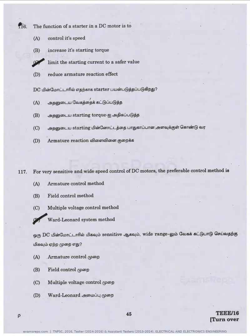
fis.   The function of a starter in a DC motor is to

       (A)     control it's speed

       (B)     increase it's starting torque

       Jiii" limit the starting current to a safer value
       (D)     reduce armature reaction effect


                                        I
       (A)     ~~®fmLUJ C:rua;~m~ s;L...@uu@~


       (B)     ~~WJ61>LUJ starting torque-re ~~a;uu@~


       (D)     Armature reaction 6lSlm61T6lSlmm @i6l>JD5a;


117.   For very sensitive and wide speed control of DC motors, the preferable control method. is

       (A)     Armature control method

       (B)     Field control method

       (C)     Multiple voltage control method

       ~Ward-Leonard system method
       ~® DC uSIQTCLDrrl...Lrrrflro uSla;Qlt.O sensitive ~a;Qlt.O. wide range-~t.0 C:QJa;.$ a;L...@urr@ Gs:li.J6U~tD@i

       uSla;Qlt.O ~!D!D QP6!>!D ~~?

       (A)    . Armature control QP6!>!D

       (B)     Field control QP61>!!l

       (C)     Multiple voltage control QPm!D

       (D)     Ward-Leonard ~mLDuy QP6W>J!l


p                                                        45                                              TEEE/16
                                                                                                       [Turn over
Text of page 48
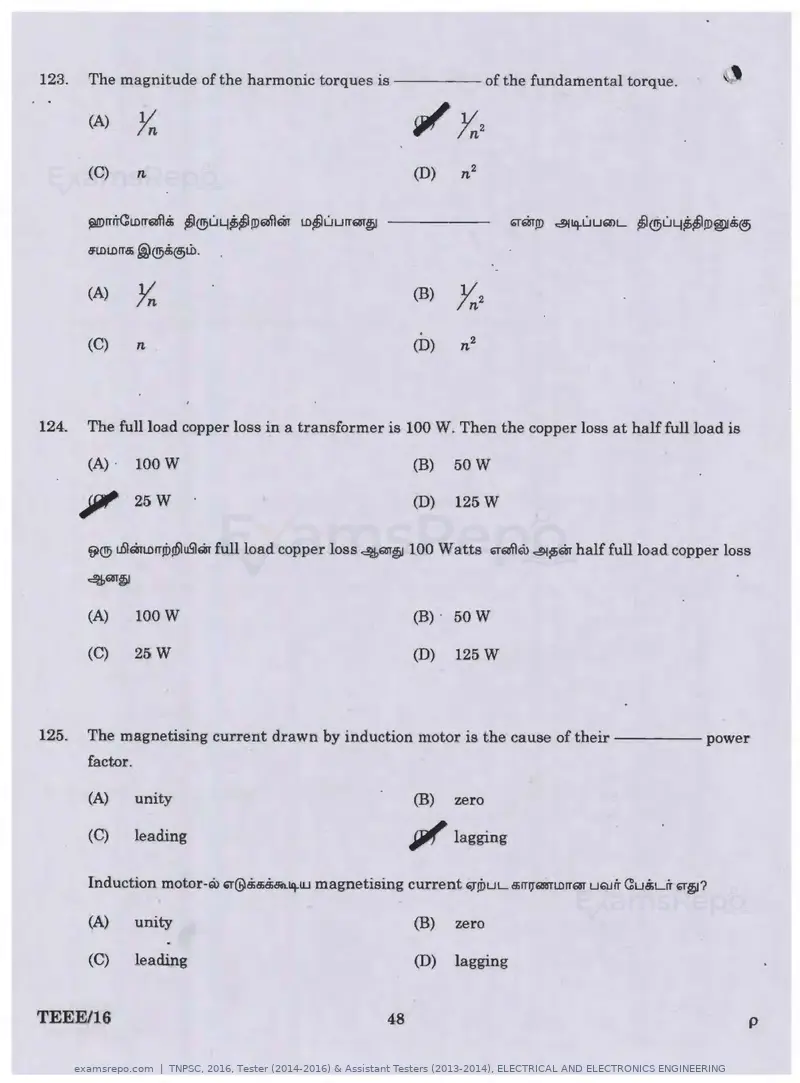
123.   The magnitude of the harmonic torques is - - - - - of the fundamental torque.

       (A)       Yn
       (C)       n                                           (D)     n2

       ~rrlTCLOrr~Bi ~®LI4~~!D~Qy LD~UUITQT~ - - - - -

       8'LDLDIT,$ .@@.i@jl.b.


       (A)       Yn                                          (B)     V2
                                                                     In
       (C)       n
                                                              .
                                                             (D)     n2


124.   The full load copper loss in a transformer is 100 W. Then the copper loss at half full load is

       (A) ·     100 W                                       (B)     50 W

       Jiii' 25 w                                            (D)     125 w


       VI® uSIQJLOrr.d>W\uS'lQir full load copper loss 4m~ 100 Watts 6T~Q.> ~~Qir half full load copper loss
       4m~


       (A)       100 W                                       (B)     50 w

       (C)       25 W                                        (D)     125 W


125.   The magnetising current drawn by induction motor is the cause of t h e i r - - - - - power
       factor.

        (A)      unity                                       (B)     zero

        (C)      leading                                     iJ1/'   lagging

       Induction motor-Q.> 6T@8ia;8iBil.iq.IU magnetising current ~.d>uL a;rrlJ"6IRITLDrrar uQ.Jir Cu5Lrr ""~?

        (A)      unity                                       (B)     zero

        (C)      leading                                     (D)     lagging


TEEE/16                                                 48                                                       p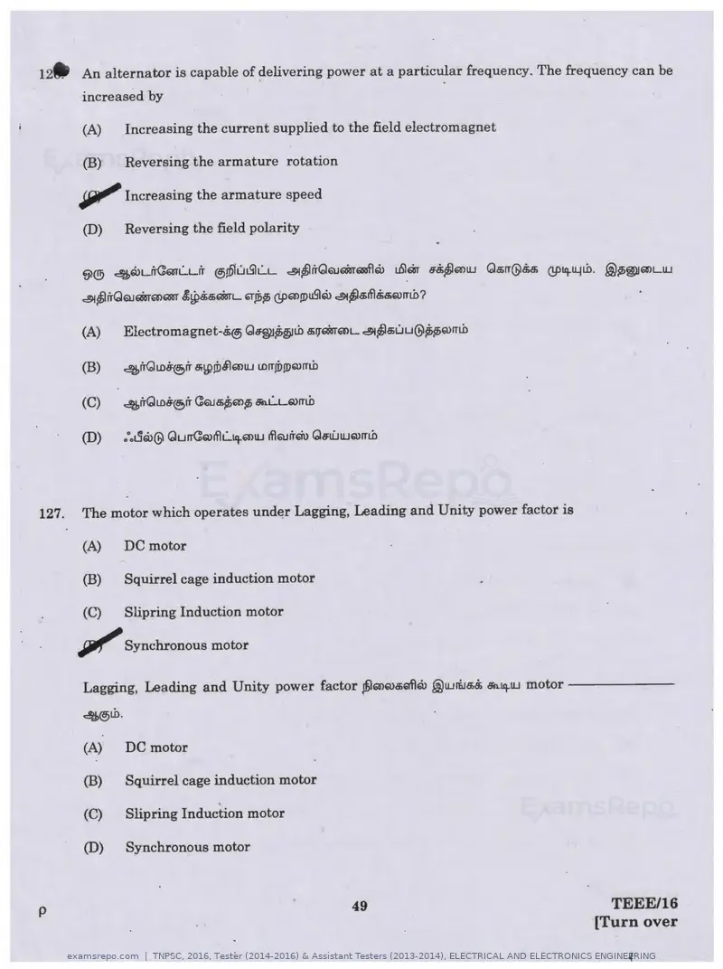
Text of page 49
12. An alternator is capable of delivering power at a particular frequency. The frequency can be
        increased by

        (A)     Increasing the current supplied to the field electromagnet

        (B)     Reversing the armature rotation

       JiJl'1" Increasing the armature speed
        (D)     Reversing the field polarity


        ~® 46i>LfrC6'TL.Lir ®!Dlui51L.L ~~frQQJQirrQGflQ> uSlm .M~Q)UJ Q5rr@&a; (!;Ptq.~tb . .@lb~mLUJ
        ~~rTQQJ~6'&)Ql!T .§i~8;c$~L '1'Jfilb (!;P6W>!Du.SJQ) ~~5rfl,$5Q)rrtb?


127.   The motor which operates under Lagging, Leading and Unity power factor is

       (A)      DC motor

       (B)      Squirrel cage induction motor

       (C)      Slipring Induction motor

       JJllf" Synchronous motor
       Lagging, Leading and Unity power factor ~Q>Q>a;61fl6b .@UJri.Je,,!i; ~tq.UJ m o t o r - - - - - -
       4®LD.

       (A)     DC motor

       (B)     Squirrel cage induction motor

       (C)     Slipring Induction motor

       (D)     Synchronous motor


p                                                            49                             TEEE/16
                                                                                          [Turn over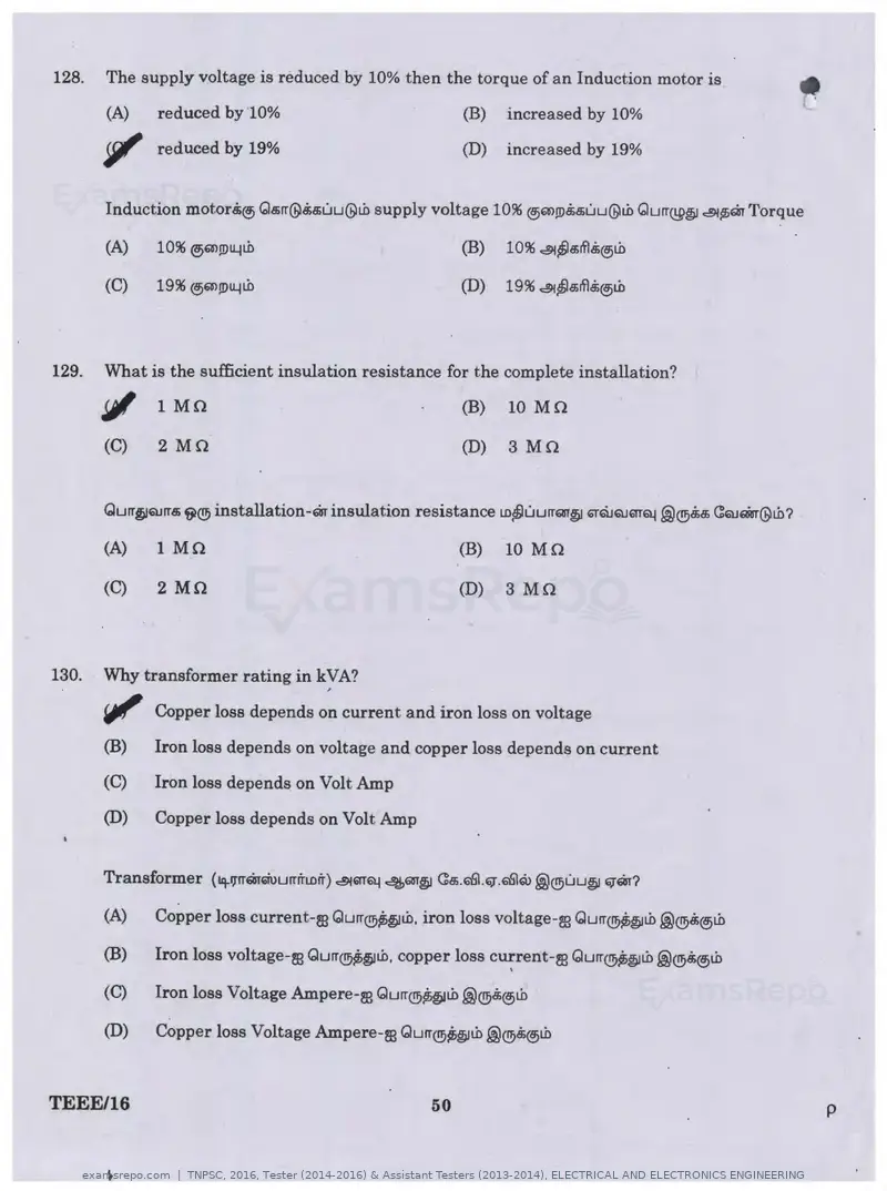
Text of page 50
128.   The supply voltage is reduced by 10% then the torque of an Induction motor is                                •

       (A)     reduced by 10%                                 (B)   increased by 10%

       ~ reduced by 19%                                       (D)   increased by 19%


       Induction motorSi@) Qs;rr@S;s;uu@Lb supply voltage 10% @)OO!D.$s;uu@Lb Gurr@~ ~~EiisT Torque

       (A)    10% ®m!Du..iL.b                                 (B)   10% ~~a;rll.$@.)Lb

       (C)    19% @)msou..iL.b                                (D)   19% ~~s;rll.$@>Lb


129.   What is the sufficient insulation resistance for the complete installation?

       J;I 1 Mn                                               (B)    10 Mn

       (C)     2 Mn                                           (D)    3 Mn


       Gurrj!Eil.HT8i f;)(!!; installation-EiisT insulation resistance LD~uurrQITjl GTQJQJ6fTQ.j @®" (!QiQRsr@Lb?

       (A)     1 Mn                                           (B)   10 Mn

       {C)     2 Mn                                           (D)   3 Mn


130.   Why transformer rating in kVA?

       ~ Copper loss depends on current and iron loss on voltage
       (B)     Iron loss depends on voltage and copper loss depends on current

       (C)     Iron loss depends on Volt Amp

       (D)    Copper loss depends on Volt Amp


       (A)     Copper loss current-m Qurr®~j!Lb. iron loss voltage-m Gurr~j!Lb @®Bi®Lb

       (B)     Iron loss voltage-m Gurr~jltb. copper loss current-m Gurr@~j!Lb @®Bi@>Lb
                                                                     '
       (C)     Iron loss Voltage Ampere-m Gurr®~~Lb @®di@>Lb

       (D)     Copper loss Voltage Ampere-m Gurr®~~Lb@@Bi@>Lb


TEEE/16                                                  50                                                             p
Text of page 52
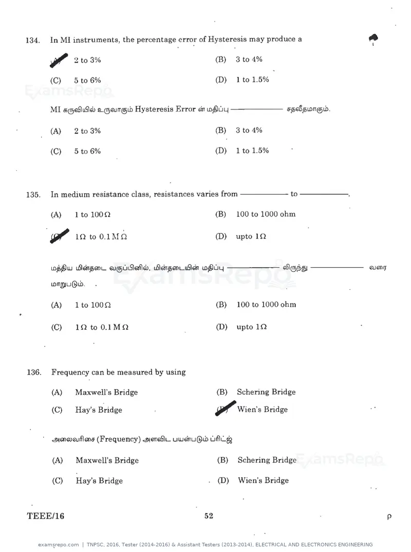
134.   In MI instruments, the percentage error of Hysteresis may produce a

       ~ 2to3%                                           (B)      3 to 4%

       (C)      5 to 6%                                  (D)      1 to 1.5%


       MI t'h@ElS!uSlQi L(!!)QHT@jl.b Hysteresis Error 6iT LD~LILI - - - - - ~~~LDIT@jl.b.

       (A)      2 to 3%                                  (B)      3 to 4%

       (C)      5 to 6%                                  (D)      1to1.5%


135.   In medium resistance class, resistances varies from - - - - - to - - - - -.

       (A)      1to10on                                  (B)      100 to 1000 ohm

       llJI"    1n to 0.1 Mn                             (D)      upto 1n


       LDU!UJ uSl6ir~Q)L QJ@jUt.Sl~Gii>. u5lm~Q'lLuS1m lD~ULj - - - - - QSJ®,{i>~ - - - - -

       lDIT!1'U@l.b.


       (A)      1to10on                                  (B)      100 to 1000 ohm

       (C)      Hl to 0.1 M n                            (D)      upto ln


136.   Frequency can be measured by using

       (A)      Maxwell's Bridge                         (B)      Schering Bridge

       (C)      Hay's Bridge                             IJll/'   Wien's Bridge


       ~Q>Q)QJif)Q>6 (Frequency) ~mElSIL UUJ6iru@lb   uifll..S!

       (A)      Maxwell's Bridge                         (B)      Schering Bridge

       (C)      Hay's Bridge                             (D)      Wien's Bridge


TEEE116                                             52                                        p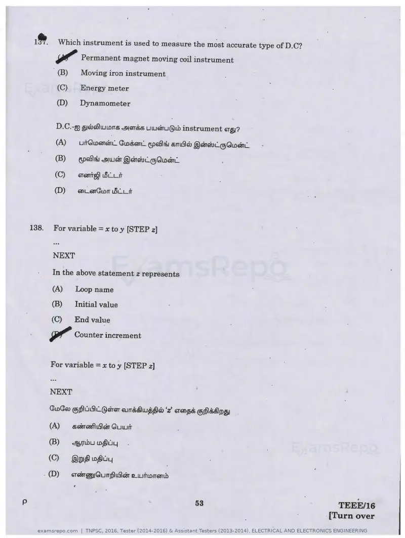
Text of page 54
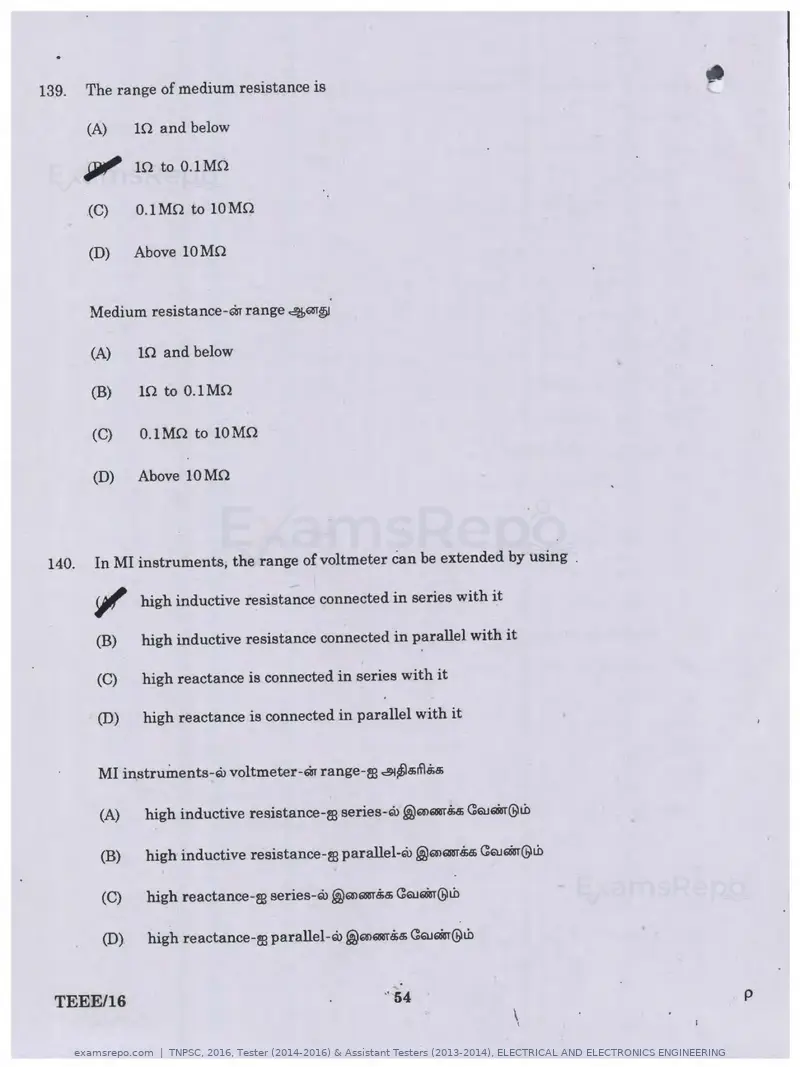
139.   The range of medium resistance is

       (A)   10 and below

       JJJll' 10 to O.lMO
       (C)   o.1Mn to 10Mn

       (D)   Above 10 Mn


       Medium resistance-oo range 4QT~

       (A)   10 and below

       (B)   ln to o.1Mn

       (C)   O.lMO to lOMO

       (D)   Above lOMn


140.   In MI instruments, the range of voltmeter can be extended by using .

       ~ high inductive resistance connected in series with it
       (B)   high inductive resistance connected in parallel with it

       (C)   high reactance is connected in series with it

       (D)   high reactance is connected in parallel with it


       MI instruinents-w voltmeter-~ range-m ~~a;if\&a;

       (A)   high inductive resistance-m series-w @mQIBl"M CQJ61iBT@tb

       (B)   high inductive resistance-m parallel-ro @mQIBTM CQJ61iBT@tb

       (C)   high reactance-m series-ro @mQIBT.$5 CaJ61iBT@tb

       (D)   high reactance-m parallel-ro@mQIBl"8;a; CaJ61iBT@tb


TEEE/16                                          .. 54                        p
                                                                   \
                                                                   I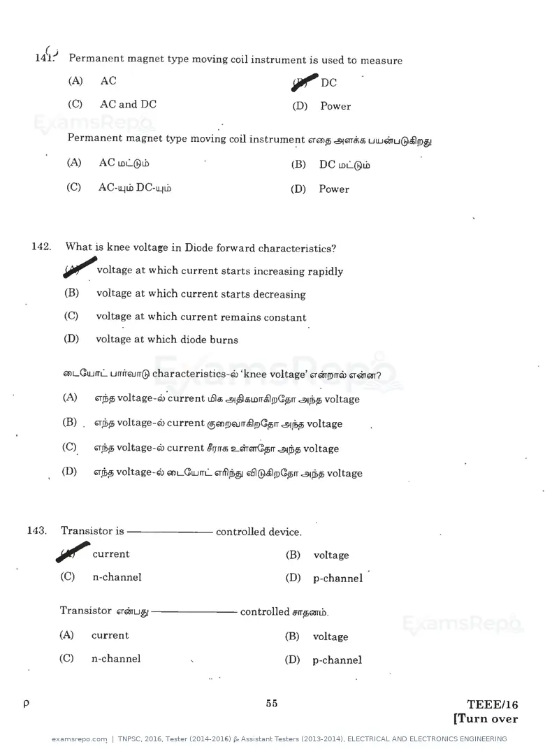
Text of page 55
14~~ Permanent magnet type moving coil instrument is used to measure
          (A)    AC                                               '1'nc
          (C)    AC and DC                                        (D)     Power


          Permanent magnet type moving coil instrument ~m,, ~mB;a; uUJQlu@.$l!!>il

          (A)    AC LDL@tb                                        (B)    DC LDL(b)Lb

          (C)    AC-11.Jtb DC-11.Jtb                              (D)    Power


142.     What is knee voltage in Diode forward characteristics?

         IJll""voltage at which current starts increasing rapidly

         (B)     voltage at which current starts decreasing

         (C)     voltage at which current remains constant

         (D)     voltage at which diode burns


         a>d~UJrrL... urrrraJrr@ characteristics-Q> 'knee voltage' '1'QJ!!>rreii> G;rQIQT?


143.     Transistor i s - - - - - - - controlled device.

        JJ"     current                                           (B)    voltage

         (C)     n-channel                                        (D)    p-channel


         Transistor '1'QJU~ - - - - - - - controlled e:rr~mtb.

         (A)    current                                           (B)    voltage

         (C)    n-channel                                         (D)    p-channel


p                                                            55                                TEEE/16
                                                                                             [Turn over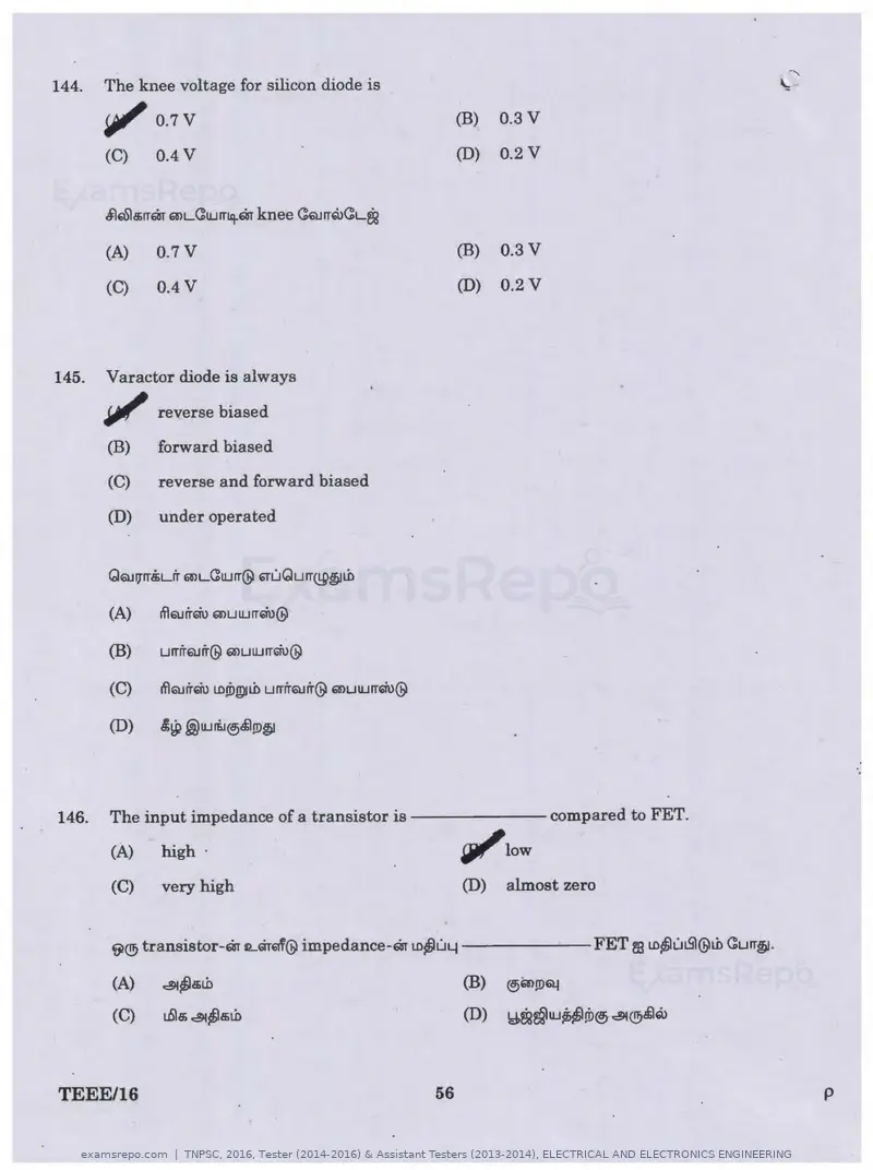
Text of page 56
144.   The knee voltage for silicon diode is                                                         '

       riJI'   0.7 v                                   (B)   0.3V
                                                                                                 '
       (C)     0.4 v                                   (D)   0.2V


       ilrota;rrm Q'lLCIUIT!q.W knee CairrQ>CL~

       (A)     0.7V                                    (B)   0.3V

       (C)     0.4 v                                   (D)   0.2V


145.   Varactor diode is always

       ~ reverse biased
       (B)     forward biased

       (C)     reverse and forward biased

       (D)     under operated


                                                                                                             ·.

146.   The input impedance of a transistor i s - - - - - - compared to FET.

       (A)     high ·                                  ~low
       (C)     very high                               (D)   almost zero


       ~® transistor-m tt.mGif@ impedance-m lD~ULj - - - - - - F E T       mLD~ut.Sl@tb Curr~.
       (A)     ~~a;tb


TEEE/16                                           56                                                     p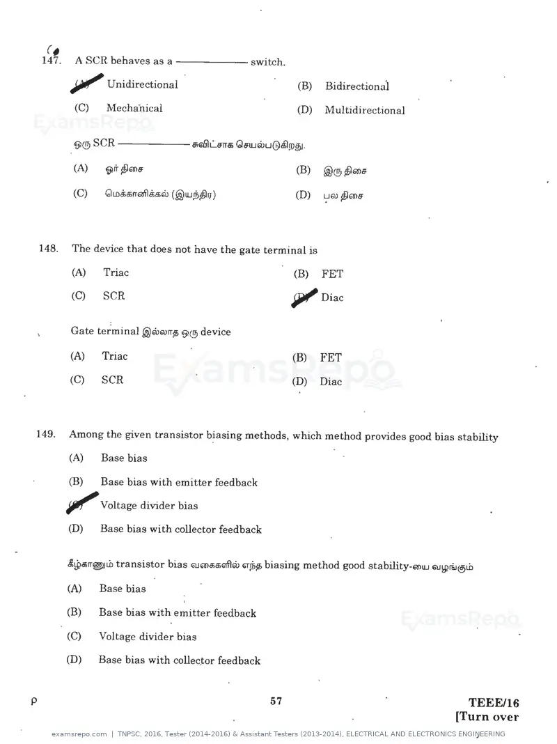
Text of page 57
c,
    147.   A SCR behaves as a - - - - - switch.

           ~Unidirectional                                     (B)   Bidirectiona'l

           (C)     Mechailical                                (D)    Multidirectional


           ~® SCR ------sr661L.lfrr5 G61Uruu@~1D~ ·

           (A)     \i}ir f)mlf


148.       The device that does not have the gate terminal is

           (A)     Triac                                      (B)    FET

           (C)     SCR                                        Jiii' Diac
           Gate terminal j)rururr15 ~® device

           (A)     Triac                                      (B)    FET

           (C}     SCR                                        (D)    Diac


149.       Among the given transistor biasing methods, which method provides good bias stability

           (A)     Base bias

           (B)     Base bias with emitter feedback

           Jllf"   Voltage divider bias

           (D)     Base bias with collector feedback


           £~a;rr@IL.b transistor bias Q.Jma;5QflQ) 6rfel6 biasing method good stability-mUJ QJWri.i@L.b


           (A)     Base bias

           (B)     Base bias with emitter feedback

           (C)     Voltage divider bias

           (D)     Base bias with collec.tor feedback


p                                                        57                                           TEEE/16
                                                                                                    [Turn over
Text of page 59
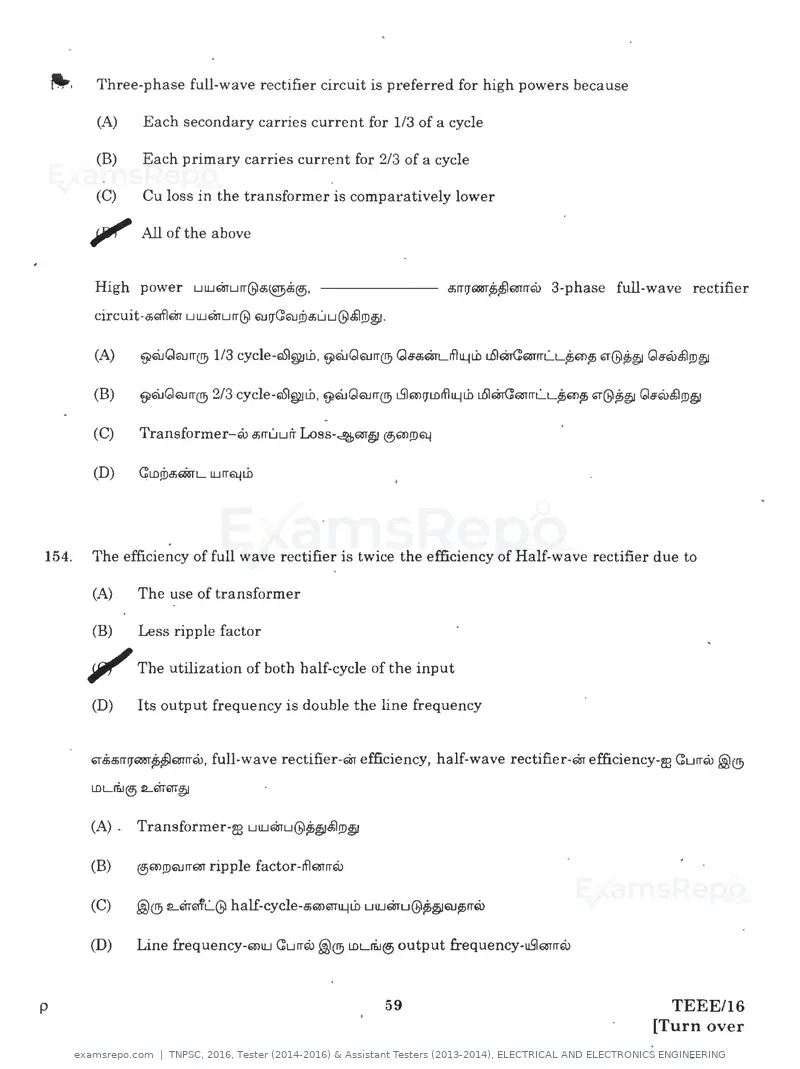
-   ·   Three-phase full-wave rectifier circuit is preferred for high powers because

             (A)      Each secondary carries current for 1/3 of a cycle

            (B)       Each primary carries current for 2/3 of a cycle

            (C)       Cu loss in the transformer is comparatively lower

            Jiii!'   All of the above


            High power          uLUmurr@a;~6.i®.                       a:.rr1J61m"P>~QTrrru   3-phase full-wave rectifier
            circuit-a:.61flm uLUmurr@ 6l.l1JGQJ!Da;Liu@.$l!D§l·


                          ,                                        .
154.        The efficiency of full wave rectifier is twice the efficiency of Half-wave rectifier due to

            (A)      The use of transformer

            (B)      Less ripple factor

            Jiii'    The utilization of both half-cycle of the input

            (D)      Its output frequency is double the line frequency


            ~6.ia;rrlJ61m~~QTrrru, full-wave rectifier-m efficiency, half-wave rectifier-m efficiency-m CurrQ> @®

            LDLri.J® L6THiTT~

            (A) .    Transformer-m uLUmu@~§l.$l!D§l

            (B)      ®a>!DQJITQT ripple factor-iflQYrrQ.l


            (D)      Line frequency-mLU Gurrru @® LDLri..i® output frequency-uS16UmQ>


p                                                             59                                             TEEE/16
                                                                                                           [Turn over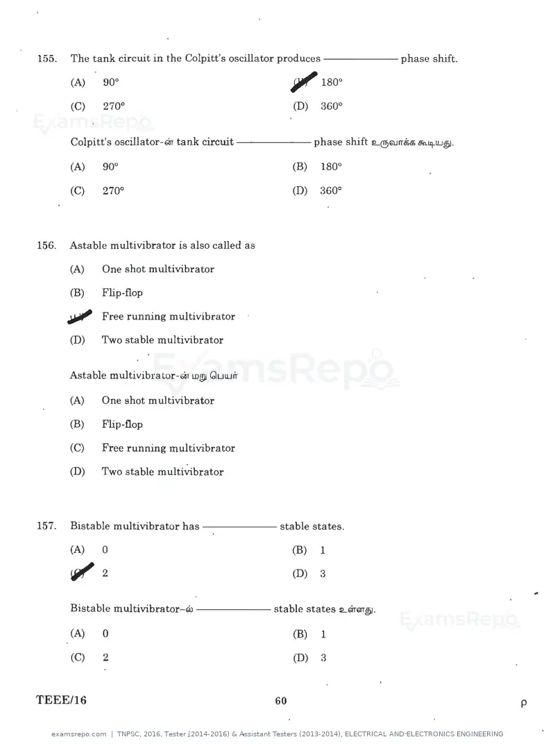
Text of page 60
155.   The tank circuit in the Colpitt's oscillator produces------ phase shift.

       (A)    90°                                     iJlf' 180°
                                                                                                 •
       (C)    270°                                    (D)    360°


       Colpitt's oscillator-m tank circuit                  phase shift L@QJrr.$a; Bin.Lq-UJ~.

       (A)    90°                                     (B)    180°

       (C)    270°                                    (D)    360°


156.   Astable multivibrator is also called as

       (A)   One shot multivibrator

       (B)    Flip-flop

       Jlill' Free running multivibrator
       (D)   Two stable multivibrator


       Astable multivibrator-m LDJP! QuUJir

       (A)   One shot multivibrator

       (B)   Flip-flop

       (C)   Free running multivibrator

       (D)   Two stable multivibrator


157.   Bistable multivibrator has                 stable states.

       (A)   0                                        (B)    1

       <61' 2                                         (D)    3
                                                                                                         ..
       Bistable multivibrator-m                  stable states Lmm~.

       (A)    0                                       (B)    1

       (C)    2                                       (D)    3


TEEE/16                                          60                                                  p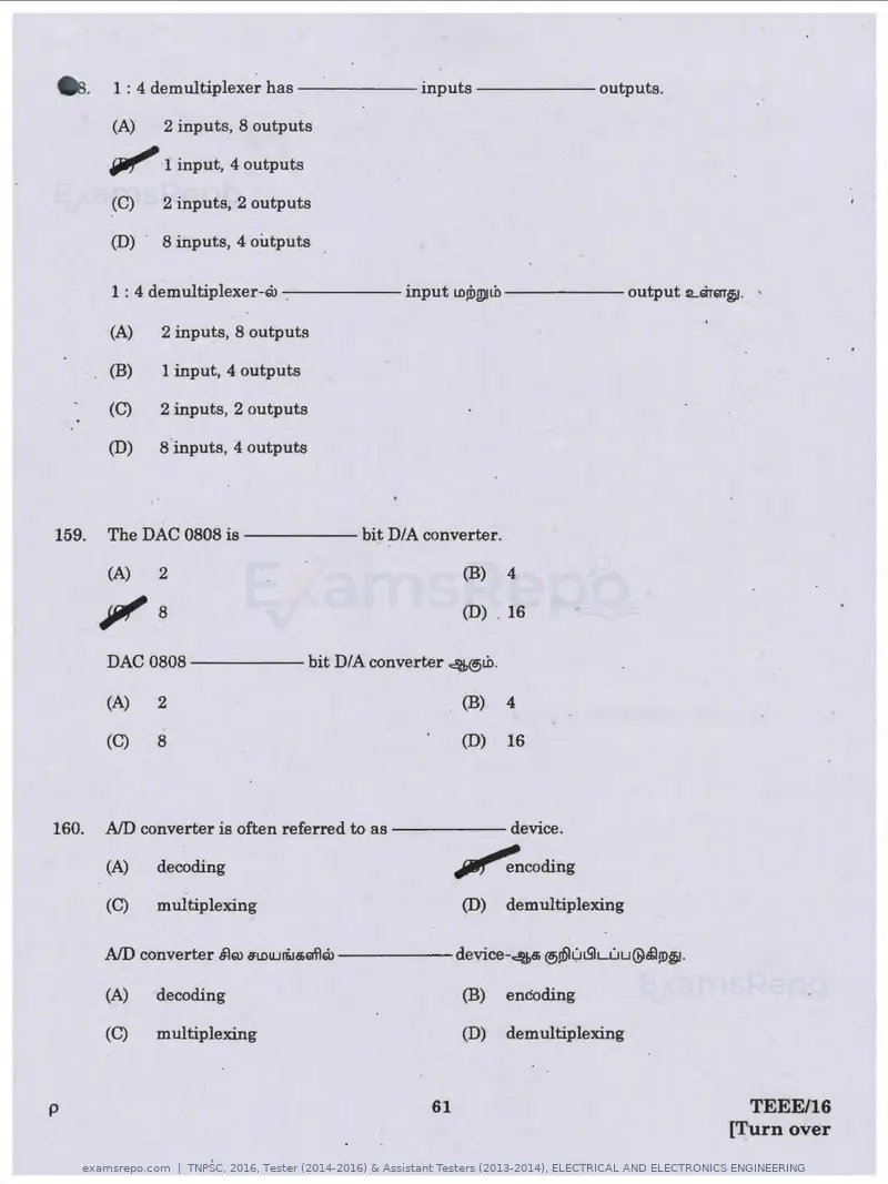
Text of page 61
•      .    1 : 4 demultiplexer h a s - - - - - - inputs ------outputs.

            (A)    2 inputs, 8 outputs

            ~ 1 input, 4 outputs
            (C)    2 inputs, 2 outputs

            (D)    8 inputs, 4 outputs

            1 : 4 demultiplexer-Qi-.- - - - - input LOJDWJt.h------ output :2....Gi"rm~. ·

            (A)    2 inputs, 8 outputs

            (B)    1 input, 4 outputs

            (C)    2 inputs, 2 outputs

            (D)    8 inputs, 4 outputs


159.       The DAC 0808 is                     bit DIA converter.

           (A)     2                                         (B)    4


           Jill'   8                                         (D) . 16


           DAC 0808                      bit DIA converter 4@t.h.

           (A)     2                                         (B)    4

           (C)     8                                         (D)    16


160.       AID converter is often referred to a s - - - - - device.

           (A)     decoding                                  ~coding
           (C)     multiplexing                              (D)    demultiplexing

           AID converter §)Q) s:wu..iri.Ja;mlru - - - - - device-4a;@iDlLii.S'ILuu@.tl!D~ ·

           (A)     decoding                                  (B)    encoding

           (C)     multiplexing                              (D)    demultiplexing


p                                                       61                                      TEEE/16
                                                                                              [Turn over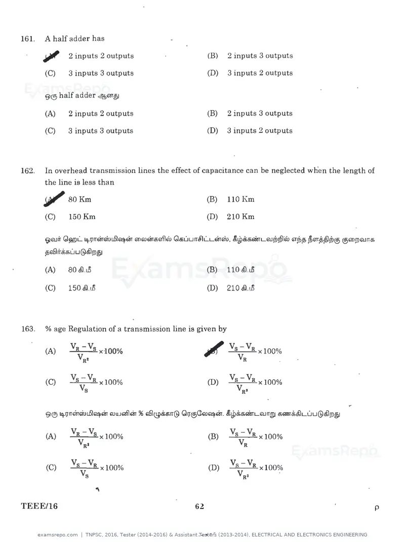
Text of page 62
161.   A half adder has

       Jllf    2 inputs 2 outputs                                   (B)   2 inputs 3 outputs
                                                                                                                    •
       (C)     3 inputs 3 outputs                               (D)       3 inputs 2 outputs

       ~® half adder ~ar~

       (A)     2 inputs 2 outputs                               (B)       2 inputs 3 outputs

       (C)     3 inputs 3 outputs                               (D)       3 inputs 2 outputs


162.   In overhead transmission lines the effect of capacitance can be neglected when the length of
       the line is less than

       , , 80Km                                                 (B)       110 Km

       (C)     150 Km                                           (D)       210 Km

       ~6tlrr Gj!WL.. iq.rprmQuuSl~m mQ>ma;Eilflru Qs;uurr.flL..Lm~. £~B;s;Eii5TL6UJD!Dlw ~~p; .ffi~~~JD® @6W>!lJaJrra;

       ~GSlrrS;a;u u@tl!JJ~

       (A)     80 tf.l.i..0                                     (B)       110 tl.i..O

       (C)     150 tf.l.i..0                                    (D)       210 .fJ.i..O


163.   % age Regulation of a transmission line is given by


       (A)      Va -Vs xl00%
                 Vat                                            ~ Vs-Va
                                                                   Va
                                                                        x100%
                                                                             .

       (C)      Vs~ Va xl00%                                        (D)    Vs-Va x100%
                       s                                                    val


       (A)                                                          (B)


       (C)                                                          (D)


TEEE/16                                                   62                                                              p


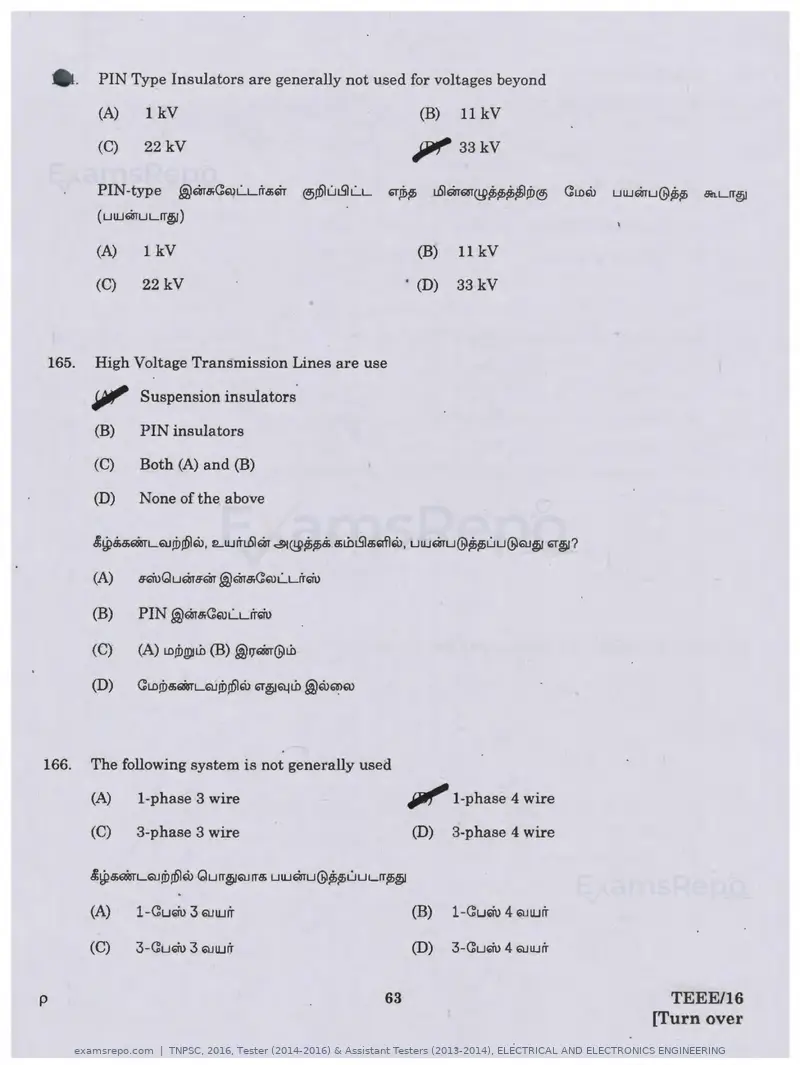
                                                           ..   ~
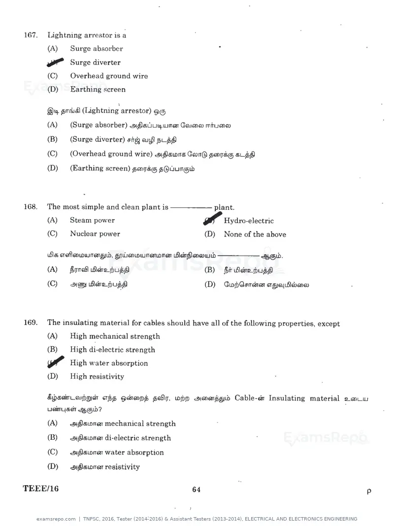
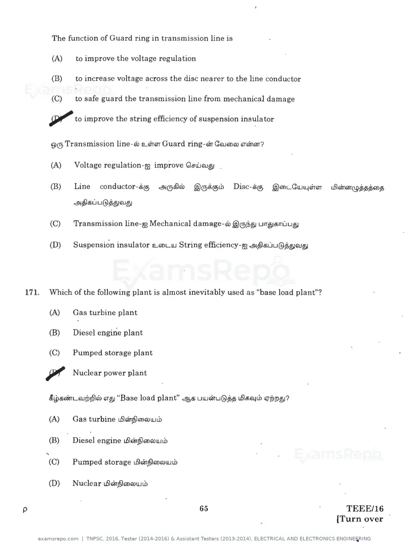
Text of page 65
9>·     The function of Guard ring in transmission line is

        (A)    to improve the voltage regulation

        (B)   to increase voltage across the disc nearer to the line conductor

        (C)   to safe guard the transmission line from mechanical damage

       ~to improve the string efficiency of suspension ins~la tor

       ~®Transmission line-w 1Lm6ll Guard ring-m (!QJQ)Q) cormm?


       (A)    Voltage regulation-m improve Ga:u'...JQ.J@ .

       (B)    Line     conductor-Bi@)      ~®~@   .@®Bi@.ii.b   Disc-.$®   .@'8>Ll'.:lUll..j~61T   u5'16irrm@~~~Q)p;

              ~~a;u u@~~Q.J~


       (C)    Transmission line-m Mechanical damage-@ .@®si>~ urr@a;rruu~

       (D)    Suspension insulator CLQ)LllJ String efficiency-al ~~a;uu@~~QJ@


171.   Which of the following plant is almost inevitably used as "base load plant"?

       (A)    Gas turbine plant

       (B)    Diesel engine plant

       (C)    Pumped storage plant

       pf Nuclear power plant

       (A)    Gas turbine uS'larjbl'8>Q)llJLb

       (B)    Diesel engine uS'lmJb!mrulULb

       (C)    Pumped storage uS'lmjblmQ)lULb

       (D)    Nuclear uS'lmjblmQ)llJLD


p                                                   65                                                TEEE/16
                                                                                                    [Turn over
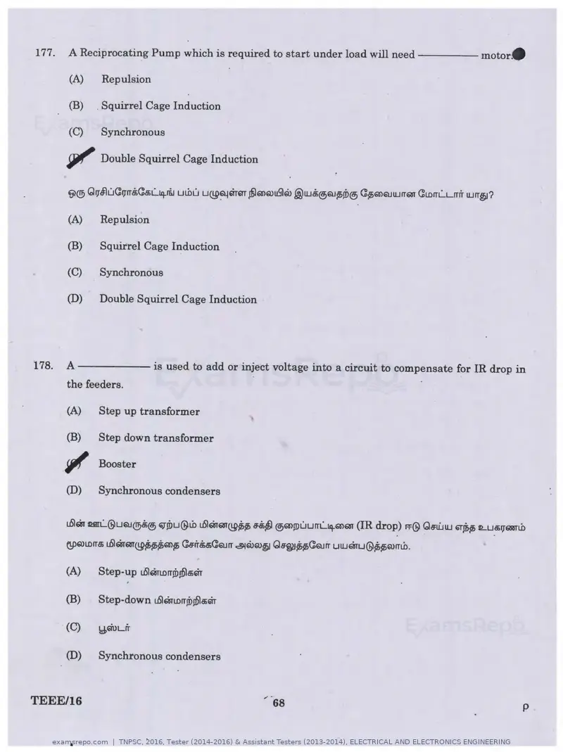
Text of page 68
177.   A Reciprocating Pump which is required to start under load will need----- motor.

       (A)    Repulsion

       (B)    Squirrel Cage Induction

       (C)    Synchronous

       , , Double Squirrel Cage Induction


       (A)    Repulsion

       (B)    Squirrel Cage Induction

       (C)    Synchronous

       (D)    Double Squirrel Cage Induction


178.   A - - - - - - is used to add or inject voltage into a circuit to compensate for IR drop in
       the feeders.

       (A)    Step up transformer

       (B)    Step down transformer

       ~ Booster
       (D)    Synchronous condensers


       u51"1r urL..@uQJ®.$® ~Jbu@tb L6l"1r(;8TQ9~~ ~ ®m!J)uurrL..l'}-m(i8T (IR drop) FF@ Gs:U:...1U ~fr>lh fl....ua;17~nb
                                                                                        .                        .


       (B)    Step-down u51"1rLDrri!>n5la;m

       (C)     Y,WLl'r


       (D)     Synchronous condensers


TEEE/16                                                                                                                 p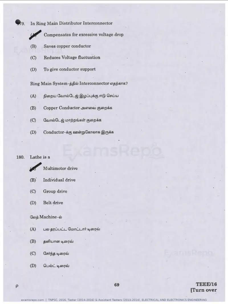
Text of page 69
. 9.    In Ring Main Distributor Interconnector

       .Jll"   Compensates for excessive voltage drop

        (B)    Saves copper conductor

        (C)    Reduces Voltage fluctuation

        (D)    To give conductor support


       Ring Main Syst~m-~~ru lnterconnector G;Tp>!Da;rra;?


       (B)     Copper Conductor <::!91EiTTa>QJ ®a>JDM


180.   Lathe is a

       ""'Multi.motor drive

       (B).    Individual drive

       (C)     Group drive

       (D)     Belt drive


       C::ru~ Machine-ru


       (A)     LIQ) ~IJUULL   C::t.0rrLLITrT ~all]QJ


p                                                       69     TEEE/16
                                                             [Turn over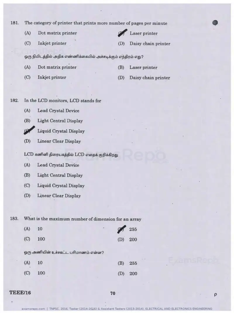
Text of page 70
181.   The category of printer that prints more number of pages per minute

       (A)     Dot matrix printer                                   '1' Laser printer           •
       (C)     Inkjet printer                                       (D)   Daisy chain printer


       (A)     Dot matrix printer
                                    .                               (B)   Laser printer

       (C)     Inkjet printer                                       (D)   Daisy chain printer


182.   In the LCD monitors, LCD stands for

       (A)     Lead Crystal Device

       (B)     Light Central Display

       SFJI' Liquid Crystal Display
       (D)     Linear Clear Display

       LCD s;QaflGfi\ j;l4"n171LJa;~~Q> LCD '1'm~& ®n5J&.$1JD~

       (A)     Lead Crystal Device

       (B)     Light Central Display

       (C)     Liquid Crystal Display

       (D)     Linear Clear Display


183.   What is the maximum number of dimension for an array

       (A)     10
                                                                    ~ 255
       (C)      100                                                 (D)   200

       ~® ~611aflu5lm 1L6a:a;l....L unlLDrrEmli> '1"68TElll?

       (A)      10                                                  (B)   255

       (C)      100                                                 (D)   200


TEEE/16                                                        70                               p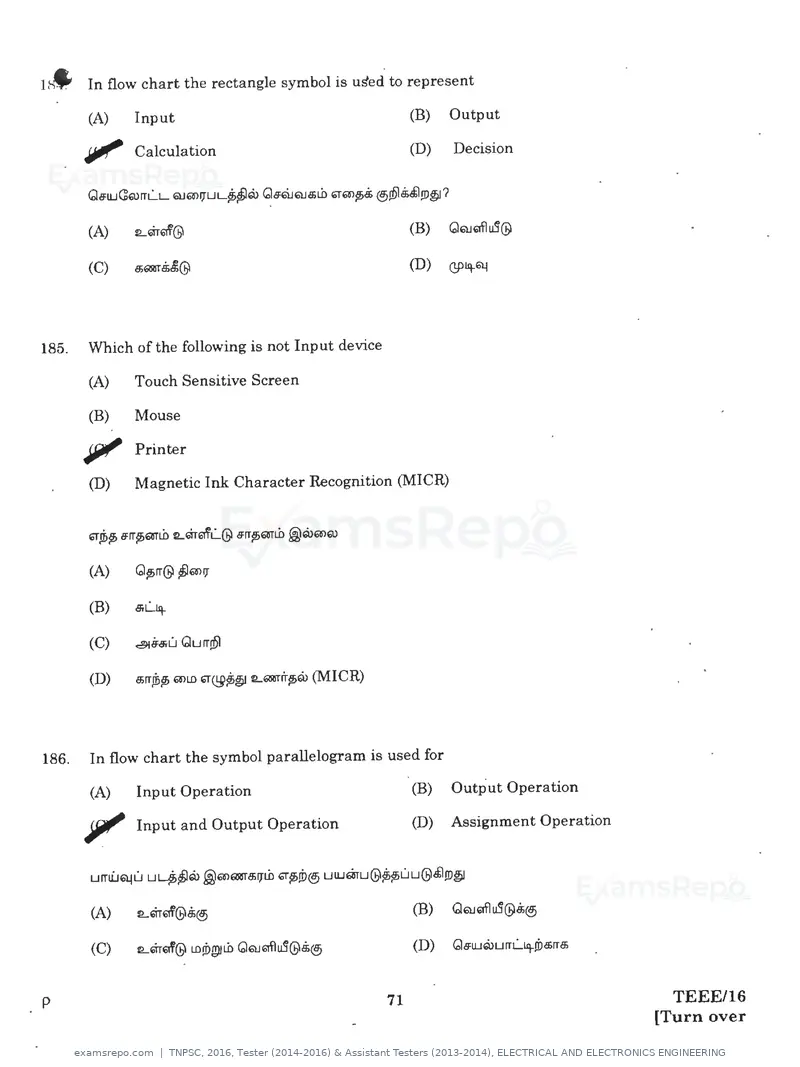
Text of page 71
1~ In flow chart the rectangle symbol is u~ed to represent
          (A)    Input                                           (B)   Output

         ~ Calculation                                           (D)    Decision


          (A)    tLQ1-'1f@

          (C)    a;Q&T.$£@


185.      Which of the following is not Input device

          (A)   Touch Sensitive Screen

         (B)    Mouse

         Jiii' Printer
         (D)    Magnetic Ink Character Recognition (MICR)


         (C)    ~6.9ru Qurr.(151


         (D)    a;rrJi>lf> mLD "'~~~ LQl&Tl'rlf>Q) (MICR)


186.     In flow chart the symbol parallelogram is used for

         (A)    Input Operation                                  (B)   Output Operation

        Jjlll' Input and Output Operation                        (D)   Assignment Operation


         (A)    tLQl-61'@8;@.i

         (C)    tLQl-af@ LD!Dgitli> QQJQfl~@5@i


p                                                           71                                  TEEE/16
                                                                                              [Turn over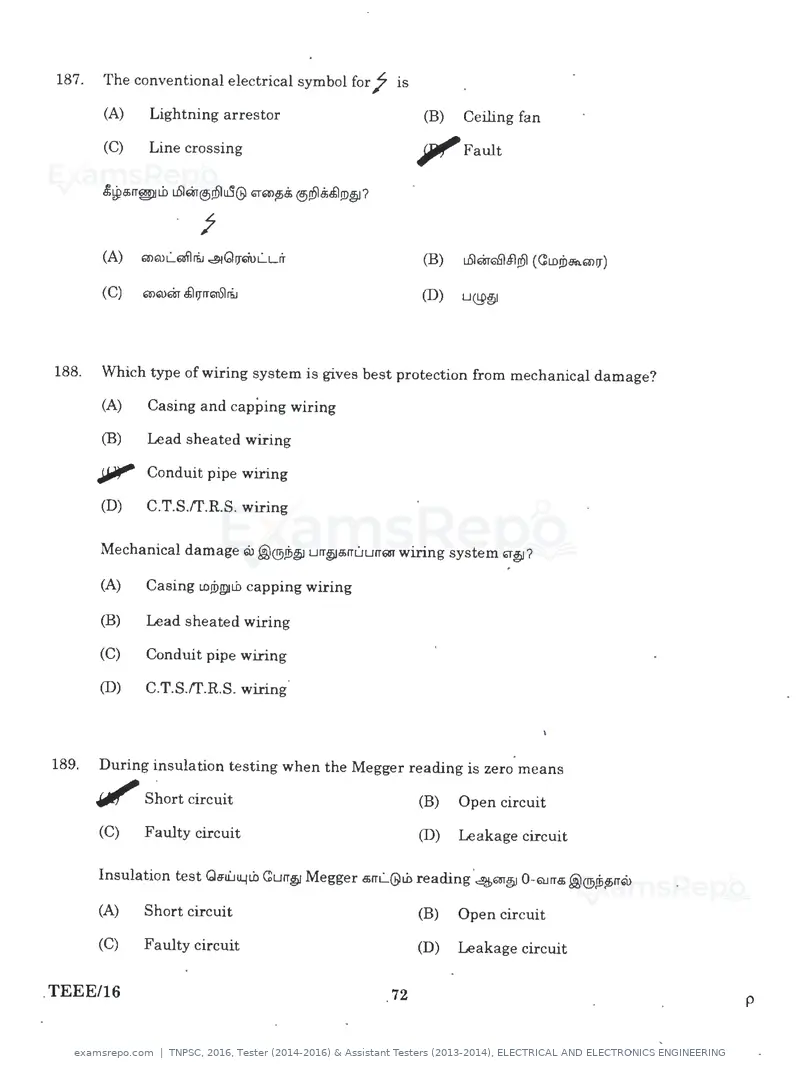
Text of page 72
187.   The conventional electrical symbol for j

       (A)    Lightning arrestor
                                                       is

                                                             (B)   Ceiling fan
                                                                                                   •
       (C)    Line crossing


188.   Which type of wiring system is gives best protection from mechanical damage?

       (A)    Casing and capping wiring

       (B)    Lead sheated wiring

       ~ Conduit pipe wiring

       (D)    C.T.S.tr.R.S. wiring

       Mechanical damage 6ll@®Ji>~ urr~c$rruurrm wiring system"°~?

       (A)    Casing LOJDI!)tb capping wiring

       (B)    Lead sheated wiring

       (C)    Conduit pipe wiring

       (D)    C.T.S.tr.R.S. wiring


189.   During insulation testing when the Megger reading is zero means

       Jiii' Short circuit                                   (B)   Open circuit

       (C)    Faulty circuit                                 (D)   Leakage circuit

       Insulation test Ge:u'...114tb Curr~ Megger a;rrL...@tb reading 4m~ 0-QJrra; @®Jiitf>rr6ll
                                                                     0


       (A)    Short circuit                                  (B)   Open circuit

       (C)    Faulty circuit                                 (D)   Leakage circuit

.TEEE/16                                                72                                             p
Text of page 73
W· The main faults which occur in underground cables are
          (A)    Earth fault

         (B)    Short circuit fault

         (C)    Open circuit fault

        , , , Earth, short circuit and .open circuit fauit


         Underground cable e;Eilflru QPB;.$1UJLDITB> 'f/i>u@t.b fault-e;m ifa>QJ?

         (A)    Earth fault

         (B)    Short circuit fault

         (C)    Open circuit fault

         (D)    Earth, short circuit and open circuit fault


191.     Interlock are used to achieve

        JI""    correct sequence of operation

         (B)    Wrong sequence of operation

         (C)    Step operation .

         (D)    Instep operation


p                                                         73                          TEEE/16
                                                                                    [Turn over
Text of page 76
197.       The fault detected by the presence of black colour gas deposited in the Bucholz relay is

           (A)      Decomposition of paper and cloth insulation
                                                                                                                   •
           (B)      Decomposition of wood insulation

           (C)      Overheated oil indication

       rjl Electric arc formation in oil
           Bucholz relay-m test Qeu'..Jll.41.0 Curr§! a;®u4 .ffil!D QJITl!.4 .@®~lf>rrQ), ~~ 61"~/f> QJQ>a;1Urrm fault-m
           ®!61.9i.tl !D§I?

           (A)       Paper LDJDl!.)ILO cloth insulation decomposition 4.$1 .@®ULIQ>jf>

           (B)       Wood insulation decomposition 4£1 .@®LILIQ>jf>


           (D)       Oil-Q, Electric arc IL(!!JQJrr.tlu51(!!)uLIQ>~


198.       Transformer cores are laminated in order to

           (A)       simplify its construction

       ,             minimise eddy current loss

           (C)       reduce cost

           (D)       reduce hysteresis loss


           (A)       ~~@JQ>L!U construction-m 8iG>uLDrr8;a;


           (B)       eddy current loss-m @;Q>!DH


           (D)       hysteresis loss-m @;Ql!DM


TEEE/16                                                          76                                                    p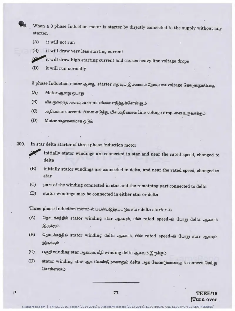
Text of page 77
tt9. When a 3 phase Induction motor is starter by dii:ectly connected to the supply without any
            starter,
            (A)    it will not run
            (B)    it will draw very less starting current
           IJJ¥"'it will draw high starting current an~ causes heavy line voltage drops
            (D)    it will run normally


            3 phase Induction motor 4m~. starter "'"~~Lb .@Q>Q)rrtnru GJlil'f~wrra; voltage Qa;rr@S;@)Li>Gurr§I

            (A)    Motor 4m~ 9Lrr~

           (B)     t.6la;@>Q'l,!D.ffi~ ~6TT~ current-u9Q'l6DT ~@~~S;Qa;rrm~Lb

           (C)     ~~a;LDrrQJT current-u9mQJT ~@~~· L.6la; ~~a;LDrrQT line voltage d.rop-6'l6BT IL@QJrr.$@>tb

           (D)     Motor e:rr~rrv~n.orra; 9(9Lb


.   200.   In star delta starter of three phase Induction motor
           JtJI/' initially stator windings are connected in star and near the rated speed, changed to
                  delta
           (B)    initially stator windings are connected in delta, and near the rated speed, changed to
                  star
           (C)    part of the winding connected in star and the remaining part connected to delta
           (D)    stator windings may be connected in either star or delta


           Three phase Induction motor-Q> uwQ1'u@~~uu@Lb star delta starter-Q>

           (A)    Q~rru~~Q> stator winding           star ~.s~Lb. t.SlQ1' rated speed-Q1' Gurr~ delta 4a;~Lb
                  .@~@>Lb

           (B)    Q~rr~Q> stator winding             delta 4a;~Lb. t.SlQ1' rated speed-Q1' Gurr~ star 4a;~Lb
                  .@®8i@>Lb

           (C)    LI@)~ winding star ~~tb. t/5~ winding delta c:!ijfft~Lb .@®8;@ii.b

           (D)    stator winding star-~ GQJar@tnrrQJTrrWJtb delta ~ GQJar@tnrr6&1rrWJLb connect Q.,u'..J~
                  Qa;rrQr6TTrurri.b


    p                                                      77                                          TEEE/16
                                                                                                     [Turn over
Text of page 78
SPACE FOR ROUGH WORK
                                     •
                                 ,


                                         ..
                                         •


TEEE/16             78                   p
Text of page 79
•   SPACE FOR ROUGH WORK


p               79               TEEE/16
                               [Turn over
Text of page 80
TEEE/16       •
                                                                ~::~:~ I I I I I I I I I I
                                                    2016
            ELECTRICAL AND ELECTRONICS ENGINEERING
                        (Diploma Standard)
Time Allowed : 3 Hours]                                                             [Maximum Marks : 300
         Read the following instructions carefully before you begin to answer the questions.

                                       IMPORTANT INSTRUCTIONS

1.      This Booklet has a cover (this page) which should not be opened till the Invigilator gives signal to open
        it at the commencement of the examination. As soon as the signal is received you should tear the right
        side of the booklet cover carefully to open the booklet. Then proceed to answer the questions.
2.      This Question Booklet contains 200 questions. Prior to attempting to answer the candidates are
        requested to check whether all the questions are there in series without any omission and ensure there
        are no blank pages in the question booklet. In case any defect in the Question Paper is noticed it shall
        be reported to the Invigilator within first 10 minutes.
3.      Answer all questions. All questions carry equal marks.
4.      You must write your Register Number in the space provided on the top right side of this page. Do not
        write anything else on the Question Booklet. ·
5.      An Answer Sheet will be supplied to you separately by the Invigilator to mark the answers.
6.      You will also encode your Register Number, Subject Code, Question Booklet Sl. No. etc. with Blue or
        Black ink Ball point pen in the space provided on the side 2 of the Answer Sheet. If you do not encode
        properly or fail to encode the above information, action will be taken as per Commission's notification.
7.      Each question comprises four responses (A), (B), (C) and (D). You are to select ONLY ONE correct
        response and mark in your Answer Sheet. In case, you feel that there are more than one correct
        response, mark the response which you consider the best. In any case, choose ONLY ONE response for
        each question. Your total marks will depend on the number of correct responses marked by you in the
        Answer Sheet.
8.    · In the Answer Sheet there are four circles @ ,@ ,    ©      and@ against each question. To answer the
        questions you are to mark with Blue or Black ink Ball point pen ONLY ONE circle of your choice for
        each question. Select one response for each question in the Question Booklet and mark in the Answer
        Sheet. If you mark more than one answer for one question, the answer will be treated as wrong. e.g. If
        for any item,@ is the correct answer, you have to mark as follows :
                                                 @•©@
9.     You should not remove or tear off any sheet from this Question Booklet. You are not allowed to take
       this Question Booklet and the Answer Sheet out of the Examination Hall during the examination.
       After the examination is concluded. you must hand over your Answer Sheet to the Invigilator. You are
       allowed to take the Question Booklet with you only after the Examination is over.
10.    The sheet before the last page of the Question Booklet can be used for Rough Work.
11.    Failure to comply with any of the above instructions will render you liable to such action or penalty as
       the Commission may decide at their discretion.
12.    In all matters and in cases of doubt, the English Version is final.
13.    Do not tick·mark or mark the answers in the Question booklet.
                                                                                                              p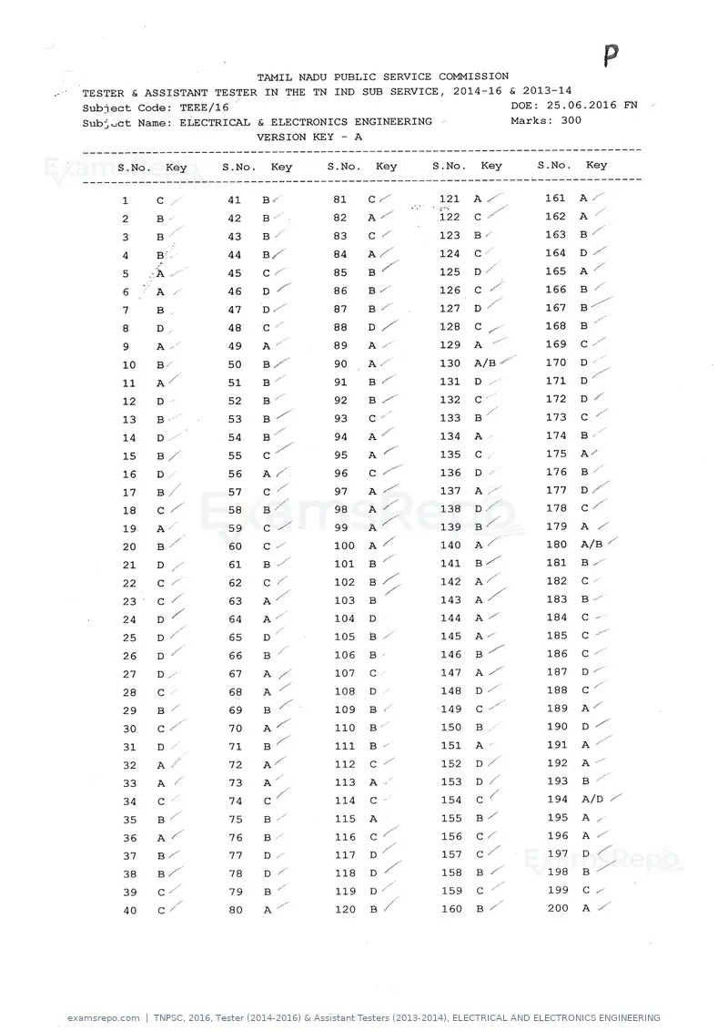
Page 1 of 80
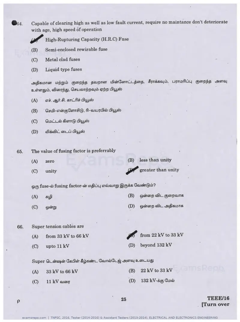
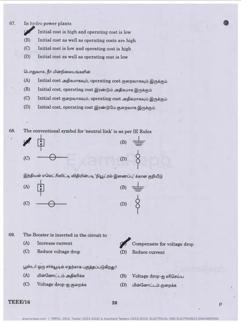
Source: Tamil Nadu Public Service Commission. Question paper published by Tamil Nadu Public Service Commission.