Machine-translated by Google. Questions are authored in English.
Top

Engineering Mechanics Questions and Answers by Topic

  • 12 topics
  • 66 questions
  • 66 from past papers
  • asked in 8 exams

Asked in these exams

ExamQuestionsYears
GATE XE 27 2012-2026
GATE ME 21 2012-2026
RSMSSB 8 2025
RSMSSB JE 8 2025
DSSSB JE 5 2023
DSSSB TGT 2 2023
GATE AE 2 2022
DSSSB 1 2023

Recent past-paper questions

GATE XE 2026

The force (F) acting on the block, as shown in the figure is 2 N. The stiffness of the spring (k) is 100 N/m.

Assume that the block is in static equilibrium and its mass is negligible.

If the static deflection of the spring \((\Delta)\) is 0.01 m, which one of the following is the corresponding angle \((\theta)\) in radians?
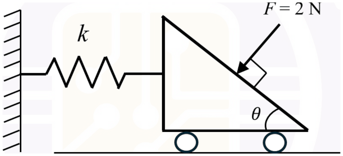
A right-angled wedge block on rollers is attached by a spring k to a wall on its left; its sloping face makes angle theta with the base, and the force F = 2 N presses on the sloping face at right angles to it

  1. A. \(\frac{\pi}{3}\)
  2. B. \(\frac{\pi}{4}\)
  3. C. \(\frac{\pi}{5}\)
  4. D. \(\frac{\pi}{6}\)
Answer and explanation

Answer: D

The angle is \(\theta = \frac{\pi}{6}\).

The force F is normal to the sloping face, which makes angle \(\theta\) with the horizontal base, so F makes the same angle \(\theta\) with the vertical. Its horizontal component pushes the block towards the wall and is resisted by the spring; the vertical component is taken by the floor.

\[ \begin{aligned} F\sin\theta &= k\Delta = 100 \times 0.01 = 1\ \text{N} \\ \sin\theta &= \frac{1}{2},\ \theta = \frac{\pi}{6} \end{aligned} \]

Using the cosine instead of the sine gives \(\pi/3\), the complementary angle. \(\pi/4\) and \(\pi/5\) give horizontal components of 1.41 N and 1.18 N, which do not match the spring force of 1 N.
More Equilibrium of Particles questions

GATE ME 2026

A horizontal disk has a radial frictionless slot in which a small block is confined to slide. The disk turns anticlockwise about its centre with a constant angular velocity of 3 rad/s. If the block slides along the slot with a constant speed of 0.2 m/s relative to the slot, then the magnitude of Coriolis acceleration in \(\text{m/s}^{2}\) is

  1. A. 1.2
  2. B. 0.6
  3. C. 2.4
  4. D. 0.3
Answer and explanation

Answer: A

The Coriolis acceleration is 1.2 \(\text{m/s}^{2}\).

For a body moving with velocity \(v\) relative to a frame rotating at \(\omega\), with \(v\) perpendicular to the rotation axis, the Coriolis component is \(2\omega v\):

\[ \begin{aligned} a_{c} &= 2\omega v = 2 \times 3 \times 0.2 \\ &= 1.2\ \text{m/s}^{2} \end{aligned} \]

0.6 omits the factor 2, 2.4 doubles it again, and 0.3 is neither. The direction is perpendicular to the slot, but the question asks only for the magnitude.

More Kinetics of Particles questions

GATE XE 2026

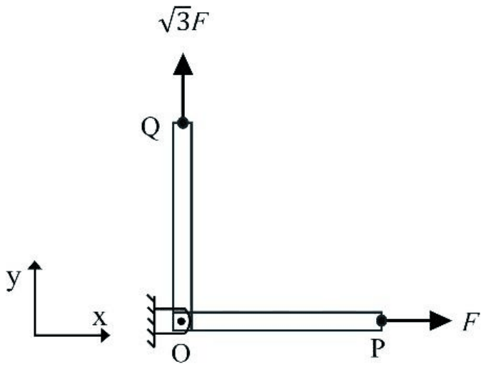
Two axial members, namely OP and OQ, are pin joined at O as shown in the figure. A force F acts at point P along the positive x direction and a force \(\sqrt{3}F\) acts at point Q along the positive y direction.

Members OP and OQ pinned at O to a wall: OP runs along the positive x direction with force F at P, OQ runs along the positive y direction with force root 3 F at Q

The resultant of the applied forces makes an angle \(\theta\) (anticlockwise from the positive x-axis).

The value of \(\theta\) is ___.

  1. A. 30°
  2. B. 45°
  3. C. 60°
  4. D. 75°
Answer and explanation

Answer: C

The resultant makes an angle of 60° with the positive x-axis.

The two forces are perpendicular, F along x and \(\sqrt{3}F\) along y. Their resultant has components (F, \(\sqrt{3}F\)), so:

\[ \begin{aligned} \tan\theta &= \frac{\sqrt{3}F}{F} = \sqrt{3} \\ \theta &= 60^{\circ},\quad |R| = 2F \end{aligned} \]

30° is the angle the resultant makes with the y-axis, a slip from swapping the components. 45° would need equal components, and 75° has no basis.

More Force Systems and Resultants questions

GATE XE 2026

Identify the zero-force member in the truss structure as shown in the figure.

Truss with bottom chord P, S, T (P to S 1 m, S to T 1 m) and top chord Q, R 1 m higher, Q above S and R above T; members PQ, QS, SR, QR, RT, PS and ST; P is pinned, T is on a roller, and a 10 kN load acts down at S

Figure is not to scale

  1. A. ST
  2. B. SR
  3. C. SP
  4. D. SQ
Answer and explanation

Answer: A

The zero-force member is ST.

Look at joint T. It meets only two members, ST (horizontal) and RT (vertical), and the roller support there gives only a vertical reaction. There is no horizontal external force at T, so horizontal equilibrium of the joint gives the force in ST as zero. RT then carries the support reaction.

The rule of thumb: at an unloaded joint, or one loaded only along one member, where two non-collinear members meet, the member not aligned with the load carries nothing.

SR, SP and SQ all carry load: the 10 kN acts at S, and SQ, SP and SR are needed to carry it to the supports.

More Analysis of Trusses and Frames questions

GATE XE 2026

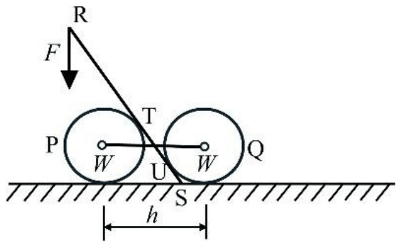
Two smooth drums each weighing \(W\) and radius, \(r\) are connected by a stiff rope of length, \(h\) as shown in the figure. Force \(F\) is applied using a massless lever (RS) of length, \(l\). The friction between the drums and the lever (RS) is negligible. The system is in static equilibrium.

Which one of the following represents the CORRECT free body diagram of the lever (RS)?

Figures are not to scale. \(N_1\), \(N_2\), and \(N_3\) in the options are reaction forces and \(F_f\) is the frictional force.

Drums P and Q joined by a rope; a lever from R, loaded by F, rests on P at T, touches Q at U and ends on the ground at S

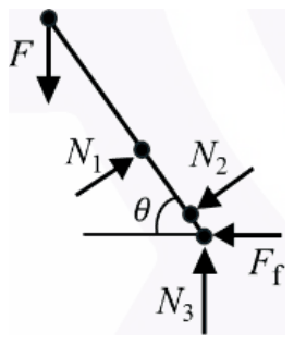
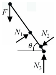
  1. A. Free body diagram of the lever with F downward at R, N1 perpendicular to the lever, N2 at the lower contact, and at S a friction force Ff to the left and N3 upward
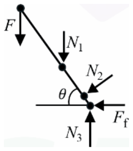
  2. B. Free body diagram of the lever with F downward, N1 vertical downward on the lever, N2 perpendicular to the lever, and at S a friction force Ff to the left and N3 upward
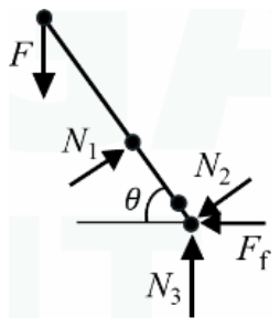
  3. C. Free body diagram of the lever with F downward, N1 perpendicular to the lever, N2 at the lower contact, and at S a friction force Ff to the left and N3 upward
  4. D. Free body diagram of the lever with F downward, N1 and N2 perpendicular to the lever, and only N3 upward at S, with no friction force
Answer and explanation

Answer: A

The correct free body diagram of the lever is (A), as the key states.

The lever RS carries the applied force \(F\) downward at R. It rests against the left drum at T and against the right drum at U, and its foot S stands on the ground. The drums are smooth and the lever-drum friction is negligible, so each drum can push on the lever only perpendicular to it. The lever lies on the upper-right side of the left drum's centre, so at T the drum pushes the lever up and to the right (\(N_{1}\), perpendicular to the lever). The lever lies on the lower-left side of the right drum's centre, so at U that drum pushes the lever down and to the left (\(N_{2}\), also perpendicular). At S the ground gives a vertical reaction \(N_{3}\) and a horizontal friction force \(F_{f}\), because the problem makes only the drum-lever friction negligible and the unequal pushes at T and U have a horizontal component to be balanced.

(B) draws \(N_{1}\) vertical, but a smooth contact force must be perpendicular to the lever. (C) applies \(N_{2}\) at the foot S instead of at the contact point U. (D) leaves out the friction force at S. Only (A) has \(N_{1}\) at T and \(N_{2}\) at U perpendicular to the lever, with both \(N_{3}\) and \(F_{f}\) at S. The choice among the diagrams follows the printed arrows; I read them on the page image and did not find a published solution to compare against.

More Equilibrium of Rigid Bodies questions

Difficulty

  • Very Easy 2
  • Easy 7
  • Medium 36
  • Hard 21

Practise

Take a timed Engineering Mechanics test 20 questions from a pool of 66.