Machine-translated by Google. Questions are authored in English.
Top

Equilibrium of Rigid Bodies Questions and Answers

1.

A bar of uniform cross section and weighing 100 N is held horizontally using two massless and inextensible strings S1 and S2 as shown in the figure.
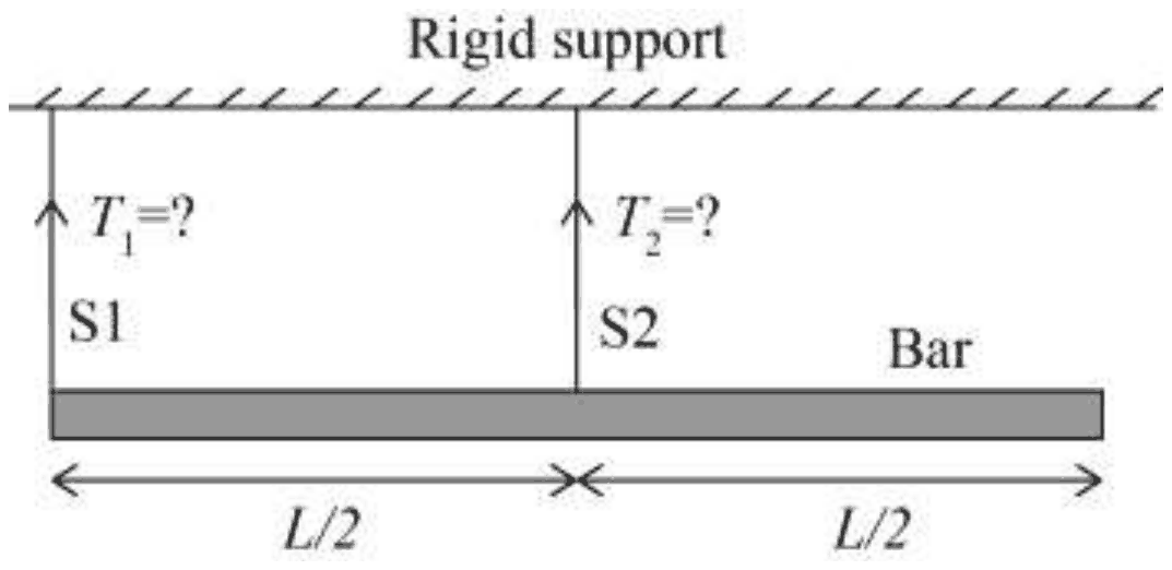
A bar of length L hangs from a rigid support by two vertical strings: S1 (tension T1) at its left end and S2 (tension T2) at its midpoint, L/2 from each end

The tensions in the strings are

Exam Year(s)

GATE ME - 2018,

Answer: B

The tensions are T1 = 0 N and T2 = 100 N.

The bar is uniform, so its 100 N weight acts at its midpoint, and string S2 is attached exactly there. Take moments about the midpoint: T2 has no moment arm, the weight has none either, and T1 acts L/2 away. For rotational equilibrium T1 × L/2 = 0, so T1 = 0, and vertical balance then gives T2 = 100 N.

Splitting the weight 75/25 or 25/75 would be right only if the strings were placed elsewhere, and T1 = 100 N with T2 = 0 would leave the weight with a moment about S1, so the bar would rotate.

Please log in or register to report this question.
2.

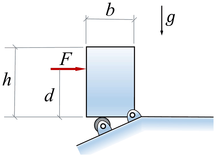
A rigid homogeneous uniform block of mass 1 kg, height \(h = 0.4\) m and width \(b = 0.3\) m is pinned at one corner and placed upright in a uniform gravitational field (\(g = 9.81\) m/s2), supported by a roller in the configuration shown in the figure. A short duration (impulsive) force \(F\), producing an impulse \(I_{F}\), is applied at a height of \(d = 0.3\) m from the bottom as shown. Assume all joints to be frictionless. The minimum value of \(I_{F}\) required to topple the block is

Upright block of width b and height h; a roller supports its bottom left corner on an inclined surface and a pin holds its bottom right corner. F acts horizontally to the right on the left face at height d

Exam Year(s)

GATE ME - 2022,

Answer: A

The minimum impulse is 0.953 Ns.

The force pushes the block towards the pinned corner, so the block starts to rotate about the pin O and lifts off the roller. Two steps: the impulse sets the angular velocity, and that kinetic energy must lift the centre of mass over O.

Impulse to angular momentum about O (the pin reaction has no moment about O):

\[ \begin{aligned} I_{F}\,d &= J_{O}\,\omega \\ J_{O} &= \tfrac{m}{3}(h^{2} + b^{2}) \\ &= \tfrac{1}{3}(0.16 + 0.09) = 0.0833 \end{aligned} \]

Energy to topple. The centre of mass starts \(h/2 = 0.2\) m above O and must rise to directly above it, at the half-diagonal \(\sqrt{0.2^{2} + 0.15^{2}} = 0.25\) m:

\[ \begin{aligned} \tfrac{1}{2}J_{O}\omega^{2} &= mg(0.25 - 0.20) = 0.4905 \\ \omega^{2} &= 11.77, \quad \omega = 3.431\ \text{rad/s} \\ I_{F} &= \frac{0.0833 \times 3.431}{0.3} = 0.953\ \text{Ns} \end{aligned} \]

Using the centroidal moment of inertia \(\tfrac{m}{12}(h^{2} + b^{2})\) instead of the one about the pin, or taking the rise of the centre of mass as the full 0.25 m, gives values that do not match; the key is the parallel-axis value about O with a rise of only 0.05 m.

Please log in or register to report this question.
3.

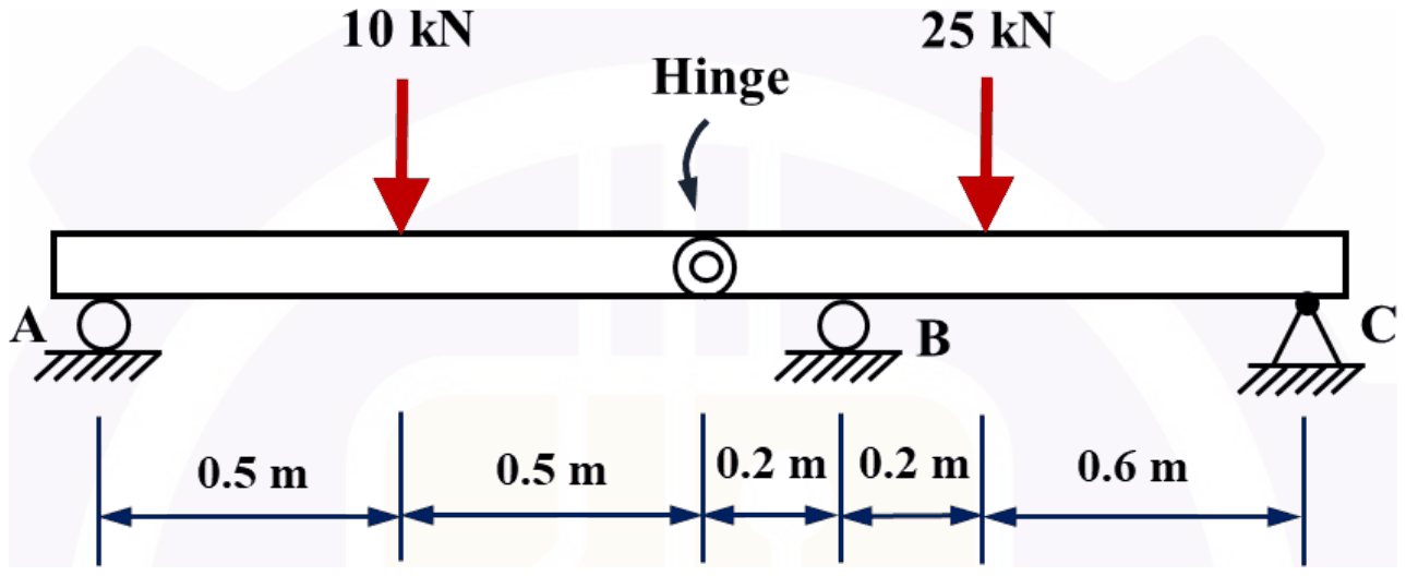
Two structural members are connected by a hinge and they are externally loaded as shown in the figure below. A and B are roller supports, and C is a pin support. Neglecting the mass of the members, the magnitude of the vertical reaction force at C in kN is

Beam on roller A, hinge, roller B and pin C. From A: 0.5 m to a 10 kN load, 0.5 m to the hinge, 0.2 m to B, 0.2 m to a 25 kN load, 0.6 m to C

Exam Year(s)

GATE ME - 2026,

Answer: A

The vertical reaction at C is 5 kN.

The hinge transmits no moment, so treat the left member A-hinge first. It is 1 m long with the 10 kN load at its middle, so A and the hinge each carry 5 kN. The hinge therefore pushes 5 kN down on the right member.

The right member runs from the hinge to C (1.0 m), with roller B 0.2 m from the hinge and the 25 kN load 0.4 m from the hinge. Take moments about B:

\[ \begin{aligned} R_{C}(0.8) &= 25(0.2) - 5(0.2) = 4 \\ R_{C} &= 5\ \text{kN} \end{aligned} \]

Then \(R_{B} = 30 - 5 = 25\) kN. Answers of 10, 15 or 20 come from treating the beam as one continuous member, ignoring the hinge's zero-moment condition.

Please log in or register to report this question.
4.

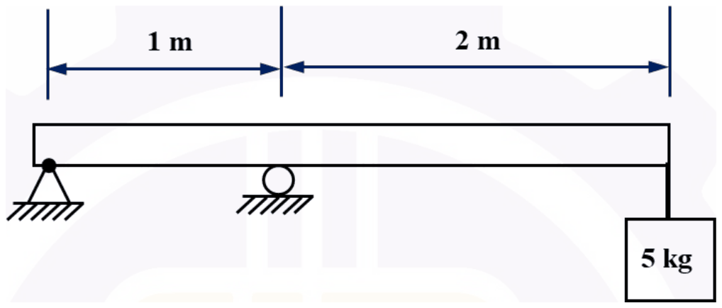
A 5 kg mass is suspended at the free end of an overhanging massless beam, having a pin support and a roller support, as shown in the figure below. Young's modulus of the material of the beam is 200 GPa and area moment of inertia of the beam is \(10^{-8}\ \text{m}^{4}\). The natural frequency of the beam in rad/s is

Beam with a pin support at the left end and a roller support 1 m away, overhanging 2 m beyond the roller to a free end carrying a 5 kg mass

Exam Year(s)

GATE ME - 2026,

Answer: A

The natural frequency is 10 rad/s.

Treat the beam as a spring under the mass. For an overhanging beam with span \(L = 1\) m and overhang \(a = 2\) m, a tip load \(F\) deflects the tip by

\[ \begin{aligned} \delta &= \frac{Fa^{2}(L + a)}{3EI} = \frac{F(4)(3)}{3EI} = \frac{4F}{EI} \\ k &= \frac{EI}{4} = \frac{200\times 10^{9}\times 10^{-8}}{4} = 500\ \text{N/m} \\ \omega_{n} &= \sqrt{k/m} = \sqrt{500/5} = 10\ \text{rad/s} \end{aligned} \]

The first term of the deflection comes from the overhang bending as a cantilever and the rest from rotation over the roller; dropping either part gives a stiffer spring and a higher, wrong frequency. 5 and the fractional values do not follow from \(k = 500\) N/m.

Please log in or register to report this question.
5.

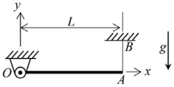
One end of a uniform rigid rod \(OA\) of length \(L\) and mass \(m\) is attached to a frictionless hinge at \(O\). The other end of the rod is connected to the roof at \(B\) with a mass-less inextensible thread \(AB\). Initially the rod is horizontal and at rest. The gravity is acting vertically downward as shown. Immediately after the thread \(AB\) is cut, the reaction on the rod at \(O\) is

A horizontal rod OA of length L hinged at O, with end A hung by a vertical thread from B on the roof; gravity downward

Exam Year(s)

GATE XE - 2022,

Answer: A

The reaction is \(\frac{mg}{4}\) in the positive y-direction.

Just after the cut the rod is still at rest, so only the angular acceleration about O matters. Taking moments about the hinge:

\[ \begin{aligned} \frac{mL^{2}}{3}\alpha &= mg\frac{L}{2},\quad \alpha = \frac{3g}{2L} \\ a_{G} &= \alpha\frac{L}{2} = \frac{3g}{4}\ \text{(downward)} \end{aligned} \]

Newton's law for the vertical motion of the centre of mass gives \(mg - R = m\cdot 3g/4\), so \(R = mg/4\), upward. mg would be the static reaction with no thread, and the downward options have the wrong sense: the hinge must still support part of the weight.

Please log in or register to report this question.
6.

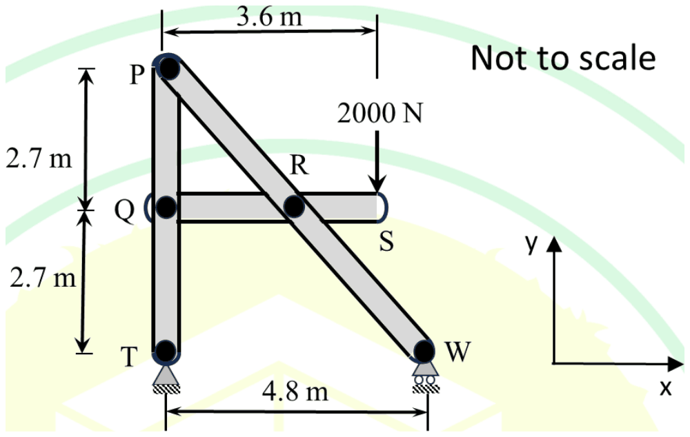
The frame shown in the figure is loaded at S with a force of 2000 N. The reactions at T are denoted by Tx and Ty, while the reaction at W is Wy. Neglect the weight of the members.

A-frame: vertical member PQT 5.4 m tall pinned at T, inclined member PRW to a roller at W 4.8 m from T, horizontal member QRS with a 2000 N downward load at S, 3.6 m from the line of PT

Which one of the following options for the magnitudes of the forces (in N), Tx, Ty and Wy, is CORRECT?

Exam Year(s)

GATE XE - 2025,

Answer: D

The reactions are \(T_{x} = 0\), \(T_{y} = 500\) N and \(W_{y} = 1500\) N.

Treat the whole frame as one free body. W is a roller, so it gives only a vertical reaction; the only other horizontal force could come from the pin at T, and there is no horizontal load, so \(T_{x} = 0\).

Take moments about T. The 2000 N load at S acts 3.6 m to the right of the line PT, and W is 4.8 m from T:

\[ \begin{aligned} W_{y} \times 4.8 &= 2000 \times 3.6 \Rightarrow W_{y} = 1500\ \text{N} \\ T_{y} &= 2000 - 1500 = 500\ \text{N} \end{aligned} \]

The internal pins at P, Q and R do not affect the support reactions of the frame as a whole. Equal shares of 1000 N would need the load midway between T and W (2.4 m), and the 1500/500 split the other way round puts the load nearer T than it is.

Please log in or register to report this question.
7.

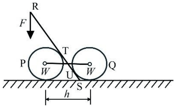
Two smooth drums each weighing \(W\) and radius, \(r\) are connected by a stiff rope of length, \(h\) as shown in the figure. Force \(F\) is applied using a massless lever (RS) of length, \(l\). The friction between the drums and the lever (RS) is negligible. The system is in static equilibrium.

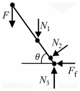
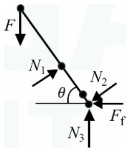
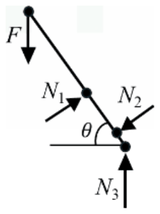
Which one of the following represents the CORRECT free body diagram of the lever (RS)?

Figures are not to scale. \(N_1\), \(N_2\), and \(N_3\) in the options are reaction forces and \(F_f\) is the frictional force.

Drums P and Q joined by a rope; a lever from R, loaded by F, rests on P at T, touches Q at U and ends on the ground at S

Exam Year(s)

GATE XE - 2026,

Answer: A

The correct free body diagram of the lever is (A), as the key states.

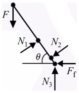
The lever RS carries the applied force \(F\) downward at R. It rests against the left drum at T and against the right drum at U, and its foot S stands on the ground. The drums are smooth and the lever-drum friction is negligible, so each drum can push on the lever only perpendicular to it. The lever lies on the upper-right side of the left drum's centre, so at T the drum pushes the lever up and to the right (\(N_{1}\), perpendicular to the lever). The lever lies on the lower-left side of the right drum's centre, so at U that drum pushes the lever down and to the left (\(N_{2}\), also perpendicular). At S the ground gives a vertical reaction \(N_{3}\) and a horizontal friction force \(F_{f}\), because the problem makes only the drum-lever friction negligible and the unequal pushes at T and U have a horizontal component to be balanced.

(B) draws \(N_{1}\) vertical, but a smooth contact force must be perpendicular to the lever. (C) applies \(N_{2}\) at the foot S instead of at the contact point U. (D) leaves out the friction force at S. Only (A) has \(N_{1}\) at T and \(N_{2}\) at U perpendicular to the lever, with both \(N_{3}\) and \(F_{f}\) at S. The choice among the diagrams follows the printed arrows; I read them on the page image and did not find a published solution to compare against.

Please log in or register to report this question.
Loading…
Tags: Equilibrium of Rigid Bodies Questions and Answers || Equilibrium of Rigid Bodies MCQ Questions and Answers || Equilibrium of Rigid Bodies GK Questions and Answers || Equilibrium of Rigid Bodies GK MCQ Questions || Equilibrium of Rigid Bodies Multiple Choice Questions and Answers || Equilibrium of Rigid Bodies GK || GK on Equilibrium of Rigid Bodies || Engineering Mechanics Questions and Answers || Engineering Mechanics MCQ Questions and Answers || Engineering Mechanics GK Questions and Answers || GK on Engineering Mechanics