
Machine-translated by Google. Questions are authored in English.
Top

V-n Diagram and Flight Envelope Questions and Answers

1.

The highest limit load factor experienced by a civil transport aircraft is in the range

Exam Year(s)

GATE AE - 2018,

Answer: B

The highest limit load factor of a civil transport lies in the range 2.0 - 5.0.

Airworthiness rules for transport aircraft set the positive limit manoeuvring load factor at about 2.5 for large airliners, rising to about 3.8 for lighter aircraft. These aircraft are not designed for violent manoeuvres, so their limit loads sit just above 2 and well below 5.

0.0 - 2.0 is too low, because steady level flight alone is 1 and even a modest turn or gust exceeds 2. 5.0 - 8.0 belongs to aerobatic aircraft, and 8.0 - 10.0 to combat aircraft, which are built for high-g manoeuvring.

Please log in or register to report this question.
2.

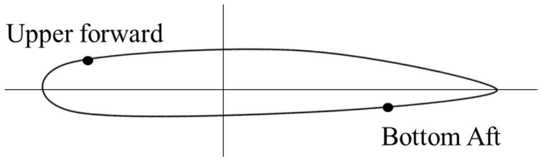
Consider the four basic symmetrical flight loading conditions corresponding to the corners of a typical V-n diagram. For one of these flight loading conditions, it is observed that (i) the compressive bending stresses have a maximum value in the bottom aft region (see figure) of the wing cross-section; and (ii) the tensile bending stresses are maximum in the upper forward region (see figure) of the wing cross-section. For the preceding observations, select the corresponding flight loading condition from the options given.

Wing cross-section with a dot on the upper surface near the leading edge labelled Upper forward and a dot on the lower surface near the trailing edge labelled Bottom Aft

Exam Year(s)

GATE AE - 2023,

Answer: D

The observations correspond to the negative low angle of attack condition.

At a corner of the V-n diagram the resultant aerodynamic force on the wing is the vector sum of lift and drag. At a high angle of attack it tilts forward relative to the chord, so it bends the wing about an axis that puts the extreme stresses in the forward upper and aft lower corners of the section. At a low angle of attack (high speed) it tilts aft, so the extreme stresses move to the aft upper and forward lower corners.

Negative load factor bends the wing downward, so the upper surface is in tension and the lower surface in compression. Combining the two: at negative low angle of attack, the compression peaks in the bottom aft region and the tension in the upper forward region, exactly as observed.

Positive load factor puts the upper surface in compression, so both positive cases are ruled out. Negative high angle of attack puts the peak compression in the bottom forward region and the peak tension in the upper aft region, the mirror of what is described.

Please log in or register to report this question.

Loading…
Tags: V-n Diagram and Flight Envelope Questions and Answers || V-n Diagram and Flight Envelope MCQ Questions and Answers || V-n Diagram and Flight Envelope GK Questions and Answers || V-n Diagram and Flight Envelope GK MCQ Questions || V-n Diagram and Flight Envelope Multiple Choice Questions and Answers || V-n Diagram and Flight Envelope GK || GK on V-n Diagram and Flight Envelope || Flight Mechanics Questions and Answers || Flight Mechanics MCQ Questions and Answers || Flight Mechanics GK Questions and Answers || GK on Flight Mechanics