
Machine-translated by Google. Questions are authored in English.
Top

Inverting and Non-Inverting Amplifiers Questions and Answers

Direction for [ Question No: 1 To 1 ] :

Read the following paragraph and answer the questions :

An operational amplifier is a direct coupled high gain amplifier with feedback. It is employed to perform a wide variety of functions such as summer, integrator, differentiator, logarithmic amplifier, oscillators, filters, comparators voltage to frequency converter, amplitude modulators, sample and hold circuit and so on. An ideal Op-Amp has infinite input resistance, zero output resistance, infinite voltage gain and bandwidth, zero offset and no drift. An ideal Op-Amp is a perfectly balanced circuit such that output voltage is zero for two equal input signals. However a real Op-Amp exhibits imbalance due to mismatch at the input differential stage. It gives rise to offsets. In practical applications offsets are removed using balancing networks. In general an Op-Amp consists of the following four stages :
(1) Differential amplifier first stage
(2) Differential amplifier second stage
(3) Emitter follower
(4) Level translator and output stage
It is most widely used analog device.

1.

If \(V_{DC}\) = 5V is applied to the input of a differentiator circuit its output will be

Exam Year(s)

UGC NET - 2012,

Answer: A

The output of a differentiator for a d.c. input of 5 V is zero, option (A). An ideal differentiator gives an output \(v_{o} = -RC\,\dfrac{dv_{i}}{dt}\), proportional to the rate of change of the input. A steady d.c. level has a rate of change of zero, so the output is zero, apart from a brief transient at the instant the voltage is applied. A square pulse, option (B), would come from a ramp input. A ramp, option (C), would come from an integrator with a d.c. input. An output of 5 V, option (D), would need a gain that has no basis here.

Please log in or register to report this question.
2.

The transfer function of the following differentiating circuit is :

(Figure: an inverting op-amp circuit. The input \(V_{1}(S)\) reaches the inverting input through R1 in parallel with a capacitor C; R2 is the feedback resistor from the output to the inverting input; the non-inverting input is grounded; the output is \(V_{2}(S)\).)

Exam Year(s)

MH SET - 2020, SET Exam - 2020,

Answer: A

The transfer function is \(-\left[\frac{R_{2}(R_{1}C_{s} + 1)}{R_{1}}\right]\), where \(C_{s}\) means C times s.

For an inverting amplifier the gain is \(-Z_{f}/Z_{in}\). Here \(Z_{f} = R_{2}\), and the input element is \(R_{1}\) in parallel with C.

\[ \begin{aligned} Z_{in} &= \frac{R_{1}}{1 + sR_{1}C} \\ \frac{V_{2}}{V_{1}} &= -\frac{R_{2}}{Z_{in}} \\ &= -\frac{R_{2}(sR_{1}C + 1)}{R_{1}} \end{aligned} \]

Option B swaps \(R_{1}\) and \(R_{2}\). Options C and D drop the minus sign of the inverting amplifier, and D also changes the sign inside the bracket.

Please log in or register to report this question.
3.

An integrator contains 100 kΩ and 1 μF capacitor. If the voltage applied to the integrator is 1 Volt, what is the output of the integrator after 1 sec ?

Exam Year(s)

MH SET - 2021, SET Exam - 2021,

Answer: A

The output is 10 V in magnitude.

An op-amp integrator gives \(v_{o} = -\frac{1}{RC}\int v_{i}\, dt\). With a constant input the output ramps linearly:

\[ \begin{aligned} RC &= 100 \times 10^{3} \times 1 \times 10^{-6} = 0.1\ \text{s} \\ |v_{o}| &= \frac{1 \times 1}{0.1} = 10\ \text{V} \end{aligned} \]

For the usual inverting integrator the output is -10 V, which is within the swing of a typical supply. 5 V and 15 V come from wrong time constants, and 0 V would mean no integration at all.

Please log in or register to report this question.

4.

The conventional rectifier works well for voltages much larger than 0.7 V. Which of the following can be used for smaller voltages (of the order of few millivolts) :

Exam Year(s)

MH SET - 2023, SET Exam - 2023,

Answer: B

For millivolt-level signals a precision rectifier is used.

An ordinary diode rectifier passes nothing until the input exceeds the diode's cut-in voltage of about 0.7 V (silicon), so a signal of a few millivolts is lost entirely. A precision rectifier places the diode inside the feedback loop of an op-amp. The op-amp's large open-loop gain divides the diode drop by that gain, so the circuit rectifies even very small signals as if the diode were ideal.

An active filter and an amplifier do not rectify. A bridge rectifier uses two diodes in each conduction path and so has an even larger threshold, about 1.4 V.

Please log in or register to report this question.

5.

Which of the following units is used to convert square wave into triangular wave ?

Exam Year(s)

MH SET - 2024, SET Exam - 2024,

Answer: B

A square wave is converted into a triangular wave by an integrator.

The output of an op-amp integrator is proportional to the time integral of its input, \(v_{o} = -\frac{1}{RC}\int v_{i}\,dt\). During each half-cycle a square wave is a constant, and the integral of a constant is a straight line, so the output ramps up during one half-cycle and down during the other. That makes a triangular wave.

A differentiator does the opposite; applied to a square wave it gives a train of spikes at the edges. A Schmitt trigger squares up a waveform rather than producing ramps, and a monostable gives a single pulse of fixed width when triggered.

Please log in or register to report this question.

6.

Instrumentation amplifier is best suited for ..........

Exam Year(s)

MH SET - 2025, SET Exam - 2025,

Answer: B

An instrumentation amplifier is best suited for detection of output from a load cell.

A load cell uses strain gauges in a Wheatstone bridge. Its output is a small differential voltage, a few millivolts, riding on a large common-mode voltage of about half the bridge supply. An instrumentation amplifier has a high input impedance on both inputs, a precisely set differential gain and a very high common-mode rejection ratio, which is exactly what is needed to amplify the bridge output accurately.

A photodiode gives a current and is normally read with a transimpedance amplifier. Signals from distant stars and RF transponders need low-noise radio-frequency receivers, not a low-frequency differential amplifier.

Please log in or register to report this question.

7.

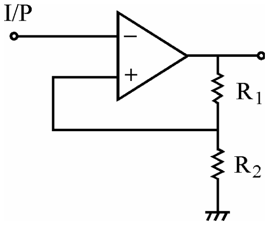
To obtain 30% feedback factor for the circuit shown below :

Operational amplifier circuit: the input I/P goes to the inverting terminal, the output drives resistor R1 in series with R2 to ground, and the junction of R1 and R2 is fed back to the non-inverting terminal.

Exam Year(s)

UGC NET - 2012,

Answer: C

The feedback factor of the network is the fraction of the output fed back to the input of the amplifier. The output is divided by R1 and R2 in series, and the feedback voltage is taken across R2, so


\[ \beta = \frac{R_2}{R_1 + R_2} = 0.3 \]
\[ R_2 = 0.3\,R_1 + 0.3\,R_2 \Rightarrow 0.7\,R_2 = 0.3\,R_1 \]
\[ 3R_1 = 7R_2 \]

Checking against the options: with 3R1 = 7R2 the ratio R2/(R1 + R2) = 3/(7 + 3) = 0.3, as required. The relation R1 = 3R2 would give a feedback factor of 0.25, 2R1 = 5R2 gives 2/7, which is about 0.29, and 5R1 = 9R2 gives 5/14, about 0.36, so none of them gives 30 per cent. The answer is 3R1 = 7R2.

Please log in or register to report this question.

8.

When Op-Amp is used as an integrator, the feedback element is

Exam Year(s)

UGC NET - 2012,

Answer: B

An op-amp integrator has a resistor in series with the inverting input and a capacitor as the feedback element, so the output is proportional to the time integral of the input: Vo = -(1/RC) ∫ Vin dt. A resistor in the feedback gives an inverting amplifier, a Zener diode in the feedback path gives a clipping or reference circuit, and a voltage divider is not a feedback element that integrates. The answer is the capacitor, option B.

Please log in or register to report this question.

9.

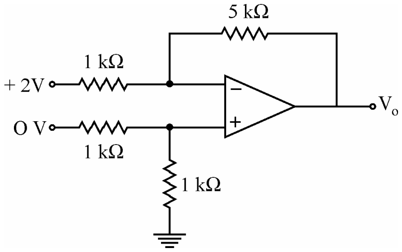
The output Vo of the ideal Op-Amp circuit shown in the figure is

Op-amp circuit: a 1 kilohm resistor joins the +2 V input to the inverting input; a 5 kilohm resistor connects the output back to the inverting input; the 0 V input reaches the non-inverting input through a 1 kilohm resistor, and a 1 kilohm resistor takes that input to ground

Exam Year(s)

UGC NET - 2012,

Answer: A

Because the non-inverting input is held at 0 V through a 1 kΩ resistor to the 0 V source and a 1 kΩ resistor to ground, no current flows into the ideal op-amp, so V+ = 0 V and the inverting input is at virtual ground. The current from the +2 V source is \( I = \dfrac{2 - 0}{1\,\text{k}\Omega} = 2\ \text{mA} \), and the whole current flows through the 5 kΩ feedback resistor, so \[ V_o = -2\ \text{mA} \times 5\ \text{k}\Omega \]\[ V_o = -10\ \text{V} \] The circuit is an inverting amplifier of gain -5 acting on 2 V, so option A, -10 V, is correct. The other values would need a different gain or an input voltage at the non-inverting terminal.

Please log in or register to report this question.

10.

For proper operation of integrators, its RC time constant and period T of the wave should be such that

Exam Year(s)

UGC NET - 2012,

Answer: B

For the proper working of an integrator, the RC time constant must be much larger than the period of the wave, \(T \ll RC\), option (B). The capacitor then charges only a small part of the way towards the input level in each period, so its voltage stays small compared with the input and the current is set nearly by the resistor alone, which makes the output the integral of the input. Option (A), \(T \gg RC\), is the condition for a differentiator, where the capacitor charges fully and the output shows only the edges. Option (C), \(T = RC\), gives an exponential response that is neither of them. Option (D) has no meaning for an integrator.

Please log in or register to report this question.

Loading…

Other Subjects

Tags: Inverting and Non-Inverting Amplifiers Questions and Answers || Inverting and Non-Inverting Amplifiers MCQ Questions and Answers || Inverting and Non-Inverting Amplifiers GK Questions and Answers || Inverting and Non-Inverting Amplifiers GK MCQ Questions || Inverting and Non-Inverting Amplifiers Multiple Choice Questions and Answers || Inverting and Non-Inverting Amplifiers GK || GK on Inverting and Non-Inverting Amplifiers || Linear Integrated Circuits Questions and Answers || Linear Integrated Circuits MCQ Questions and Answers || Linear Integrated Circuits GK Questions and Answers || GK on Linear Integrated Circuits