
Machine-translated by Google. Questions are authored in English.
Top

Performance Characteristics of Turbomachines Questions and Answers

1.

One main difference between centrifugal and reciprocating compressors is:

Exam Year(s)

DSSSB - 2023,

Answer: C

The main difference between centrifugal and reciprocating compressors is the principle by which they increase the pressure of air. A reciprocating compressor traps a volume of air and reduces it by a piston, so it is a positive displacement machine, while a centrifugal compressor raises the velocity of air by an impeller and converts this kinetic energy into pressure in a diffuser. Both compress the same kinds of gas, both handle inlet air by drawing it in, and both need lubrication in some form.

Please log in or register to report this question.
2.

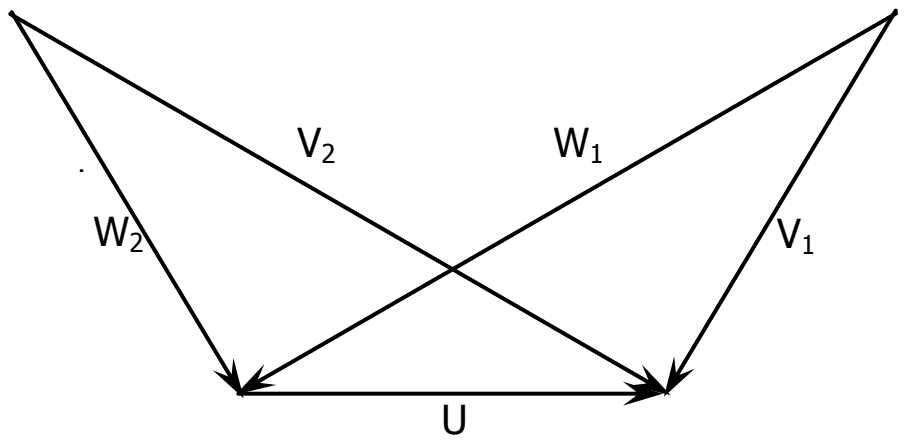
The velocity triangles at the inlet and exit of the rotor of a turbomachine are shown. V denotes the absolute velocity of the fluid, W denotes the relative velocity of the fluid and U denotes the blade velocity. Subscripts 1 and 2 refer to inlet and outlet respectively. If V2 = W1 and V1 = W2, then the degree of reaction is

Inlet and exit velocity triangles drawn on a common blade velocity vector U, with absolute velocities V1 and V2 and relative velocities W1 and W2 crossing each other

Exam Year(s)

GATE ME - 2012,

Answer: C

The degree of reaction is 0.5.

The degree of reaction is the share of the stage's energy change that takes place in the rotor as a change of relative kinetic energy. With the same blade speed U at inlet and exit:

\[ R = \frac{W_2^2-W_1^2}{(V_1^2-V_2^2)+(W_2^2-W_1^2)} \]

Substituting \(W_{2}=V_{1}\) and \(W_{1}=V_{2}\) makes the two brackets equal, so R = 1/2. The velocity triangles are mirror images, the signature of a 50 % reaction stage such as Parsons' turbine.

0 would be an impulse stage (no change in relative speed) and 1 a stage with no change in absolute kinetic energy; 0.25 matches neither condition.

Please log in or register to report this question.

Answer: B

A hydraulic coupling connects two shafts rotating at about the same speed.

A fluid coupling has a pump impeller on the driving shaft and a runner on the driven shaft, facing each other in a casing filled with oil. It transmits torque smoothly, but with a small slip, typically about 2 to 4 per cent, so the driven shaft runs at nearly the same speed as the driver.

It cannot multiply torque, since the output torque equals the input torque; that needs a torque converter with a stator, so option (C) is wrong. It is not designed to join shafts at substantially different speeds, and coupling a pump to its motor 'for efficient operation' is not its defining use.

Please log in or register to report this question.

4.

Fluid flow machine are using the principle of either (1) supplying energy to the fluid or (2) extracting energy from the fluid.Some fluid flow machine are combination of both (1) and (2) they are classified as:

Exam Year(s)

RSMSSB JE - 2025, RSMSSB - 2025,

Answer: C

They are classified as torque converters.

A torque converter contains a pump (impeller) that supplies energy to the fluid and a turbine that extracts energy from it, together with a stator, all in one casing. It therefore combines both principles, as do fluid couplings.

A compressor only supplies energy to the fluid, while a hydraulic turbine and a windmill only extract energy from it, so each uses just one of the two principles.

Please log in or register to report this question.

5.

The component of torque converter that allows torque multiplication is:

Exam Year(s)

RSMSSB JE - 2025, RSMSSB - 2025,

Answer: C

Torque multiplication comes from the stator.

In a torque converter the stator is a fixed set of curved blades between the turbine and the impeller. It turns the fluid leaving the turbine so that it re-enters the impeller in the direction of rotation, helping to drive it. The stator's reaction is what lets the output torque exceed the input torque at low speed ratios.

The impeller (pump) and turbine are also present in a fluid coupling, which cannot multiply torque. The free wheel (one-way clutch) only lets the stator spin freely once multiplication is no longer needed.

Please log in or register to report this question.

6.

Ratio of isentropic work to Euler's work in centrifugal air compressor is known as :

Exam Year(s)

RSMSSB JE - 2025, RSMSSB - 2025,

Answer: D

The ratio is the pressure coefficient.

In a centrifugal compressor, Euler's work is the work actually done on the air by the impeller, while the isentropic work is the minimum work needed for the same pressure rise. Their ratio, the pressure coefficient, shows how much of the impeller's work goes into raising the pressure.

The slip factor is the ratio of the actual whirl velocity to the ideal whirl velocity at the impeller tip. The work factor (power input factor) allows for losses such as friction and windage, and the degree of reaction is the share of the pressure rise that takes place in the impeller.

Please log in or register to report this question.

Loading…
Tags: Performance Characteristics of Turbomachines Questions and Answers || Performance Characteristics of Turbomachines MCQ Questions and Answers || Performance Characteristics of Turbomachines GK Questions and Answers || Performance Characteristics of Turbomachines GK MCQ Questions || Performance Characteristics of Turbomachines Multiple Choice Questions and Answers || Performance Characteristics of Turbomachines GK || GK on Performance Characteristics of Turbomachines || Fluid Machinery Questions and Answers || Fluid Machinery MCQ Questions and Answers || Fluid Machinery GK Questions and Answers || GK on Fluid Machinery