
Machine-translated by Google. Questions are authored in English.
Top

Network Analysis Questions and Answers

1.

A current source of 15 A with \(2\ \Omega\) resistance in parallel is equivalent to a voltage source of ______ with \(2\ \Omega\) series resistance.

Exam Year(s)

DSSSB AE - 2023,

Answer: A

A current source \(I\) with a resistance \(R\) in parallel is converted into a voltage source \(V = IR\) with the same resistance \(R\) in series (source transformation).


\[ V = 15 \times 2 = 30\ \text{V} \]


The series resistance stays at 2 ohms. The values 15 V and 7.5 V come from dividing instead of multiplying, and 5 V has no basis. The answer is 30 V, option A.

Please log in or register to report this question.
2.

What will be the power consumed by a resistor of \(1\ \mathrm{k\Omega}\) carrying a current of 20 mA?

Exam Year(s)

DSSSB AE - 2023,

Answer: B

The power dissipated in a resistor is \(P = I^2 R\). The current of 20 mA is \(0.02\) A and the resistance is \(1000\ \Omega\).


\[ \begin{aligned} P = (0.02)^2 \times 1000 \\ &= 4 \times 10^{-4} \times 10^3 = 0.4\ \text{W} \end{aligned} \]


Check with \(V = IR = 20\) V, then \(P = VI = 20 \times 0.02 = 0.4\) W. The value 4 W would come from taking the current as 63 mA, and 0.04 W or 0.004 W from slips of a power of ten when converting milliamperes. The answer is 0.4 W, option B.

Please log in or register to report this question.
3.

What is the value of equivalent resistance if a \(40\ \Omega\) resistor is connected in parallel with a \(60\ \Omega\) resistor?

Exam Year(s)

DSSSB AE - 2023,

Answer: C

For two resistors in parallel the equivalent resistance is the product over the sum.


\[ \begin{aligned} R_{eq} = \frac{40 \times 60}{40 + 60} \\ &= \frac{2400}{100} = 24\ \Omega \end{aligned} \]


The result is smaller than the smaller resistor, 40 ohms, as it must be for a parallel combination, which rules out 50 ohms and 30 ohms only as being too close to the average. The value 12 ohms is smaller than needed. The answer is 24 ohms, option C.

Please log in or register to report this question.

4.

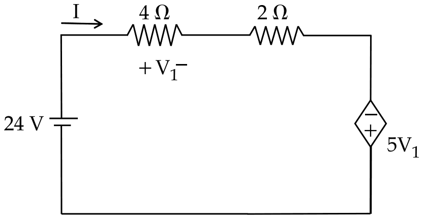
The value of current (I) flowing in the circuit shown will be :

A single loop with a 24 V source, current I through a 4 ohm resistor (voltage V1, plus at the left end) and a 2 ohm resistor, then a dependent voltage source 5V1 with its minus terminal at the top

Exam Year(s)

RSMSSB JE - 2025, RSMSSB - 2025,

Answer: C

The current has a magnitude of 1.71 A.

Go round the loop in the direction of I. The source gives a rise of 24 V, the resistors drop \(4I\) and \(2I\), and since I enters the dependent source at its negative terminal, that source gives a further rise of \(5V_{1}\). With \(V_{1} = 4I\):

\[ \begin{aligned} 24 + 5V_{1} &= 4I + 2I \\ 24 + 20I &= 6I \\ I &= -\frac{24}{14} \approx -1.71\ \text{A} \end{aligned} \]

The minus sign means the current actually flows against the marked arrow; its size is 1.71 A, which is the value the options list. If the dependent source were taken as opposing the current, the loop would give \(24 = 26I\), or 0.92 A, which is not an option, so the polarity matters.

Please log in or register to report this question.

5.

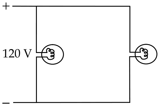
Two 60 W, 120 V light bulbs are connected across a 120 V supply as shown in figure below. The current drawn by each bulb will be :

Two bulbs connected in parallel across a 120 V supply

Exam Year(s)

RSMSSB JE - 2025, RSMSSB - 2025,

Answer: D

Each bulb draws 0.5 A.

The bulbs are in parallel across the 120 V supply, so each receives its full rated voltage and draws its rated power of 60 W.

\[ I = \frac{P}{V} = \frac{60}{120} = 0.5\ \text{A} \]

Each bulb's resistance is \(120^{2}/60 = 240\ \Omega\), which gives the same current, \(120/240 = 0.5\) A. 1 A is the total drawn from the supply by the two bulbs together, not the current in each, and 1.5 A or 2 A would mean the bulbs were running well above their rating.

Please log in or register to report this question.

6.

In the given figure, the effective Capacitance between point A and point B is __________.

Between points A and B two parallel branches: the upper has 3 microfarad and 6 microfarad capacitors in series, the lower has 2 microfarad and 2 microfarad capacitors in series

Exam Year(s)

RSMSSB JE - 2025, RSMSSB - 2025,

Answer: A

The effective capacitance is 3 µF.

Each branch is a series pair, and capacitors in series combine like resistors in parallel. The two branch results then add, because capacitors in parallel add directly.

\[ \begin{aligned} C_{1} &= \frac{3 \times 6}{3 + 6} = 2\ \mu\text{F} \\ C_{2} &= \frac{2 \times 2}{2 + 2} = 1\ \mu\text{F} \\ C_{AB} &= 2 + 1 = 3\ \mu\text{F} \end{aligned} \]

9 µF comes from adding 3 and 6 as if they were in parallel; the rules for capacitors are the reverse of those for resistors. 6 µF and 12 µF are more than the two branches can give together, since the upper branch can be no larger than its smaller capacitor, 3 µF, and the lower no larger than 2 µF.

Please log in or register to report this question.

7.

In the given figure, three equal resistors are connected. The equivalent resistance between point A and B is __________.

Three resistors R in series from A through Q and P to B; a wire joins A directly to P and another wire joins Q directly to B

Exam Year(s)

RSMSSB JE - 2025, RSMSSB - 2025,

Answer: C

The equivalent resistance is R/3.

Follow the two connecting wires. One joins A directly to P, so A and P are the same node. The other joins Q directly to B, so Q and B are the same node. Now look at where each resistor's ends fall:

  • A to Q: between A and B.
  • Q to P: between B and A.
  • P to B: between A and B.

All three resistors are connected between the same two nodes, so they are in parallel.

\[ \begin{aligned} \frac{1}{R_{AB}} &= \frac{1}{R} + \frac{1}{R} + \frac{1}{R} \\ &= \frac{3}{R}, \quad R_{AB} = \frac{R}{3} \end{aligned} \]

3R treats the resistors as a plain series chain and ignores the two wires, and 2R/3 and 3R/2 come from treating only part of the network as shorted.

Please log in or register to report this question.

Loading…
Tags: Circuit Elements and Sources Questions and Answers || Circuit Elements and Sources MCQ Questions and Answers || Circuit Elements and Sources GK Questions and Answers || Circuit Elements and Sources GK MCQ Questions || Circuit Elements and Sources Multiple Choice Questions and Answers || Circuit Elements and Sources GK || GK on Circuit Elements and Sources || Network Analysis Questions and Answers || Network Analysis MCQ Questions and Answers || Network Analysis GK Questions and Answers || GK on Network Analysis