
Machine-translated by Google. Questions are authored in English.
Top

Transient Analysis Questions and Answers

1.

A circuit is shown in figure is in steady state, when switched on at t = 0. Assuming that the inductance is ideal, the current through inductor at t = 0+ equals :
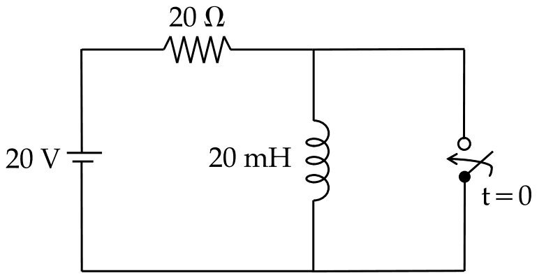
A 20 V source in series with a 20 ohm resistor feeds a 20 mH inductor; a switch marked t = 0 is connected across the inductor

Exam Year(s)

RSMSSB JE - 2025, RSMSSB - 2025,

Answer: B

The inductor current at \(t = 0^{+}\) is 1 A.

Before the switch operates the circuit is in steady state, and an ideal inductor carrying direct current behaves as a short circuit. So the whole 20 V appears across the 20 Ω resistor:

\[ i_{L}(0^{-}) = \frac{20}{20} = 1\ \text{A} \]

The current through an inductor cannot change instantaneously, because that would need infinite voltage, so \(i_{L}(0^{+}) = i_{L}(0^{-}) = 1\) A. Closing the switch across the inductor only lets that current circulate through the switch, where it stays in the ideal case.

0 A ignores the continuity of inductor current, and 0.5 A or 2 A do not follow from the circuit values.

Please log in or register to report this question.
2.

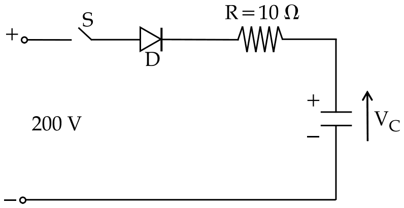
In figure given below, capacitor 'C' is charged to V0 = 100 V with upper plate positive. At time t = 0, switch S is closed. Current through the circuit at t = 0 and final voltage across 'C' are __________.

A 200 V source in series with switch S, diode D and R = 10 ohm charging a capacitor whose upper plate is plus and whose voltage is VC

Exam Year(s)

RSMSSB JE - 2025, RSMSSB - 2025,

Answer: B

The current at \(t = 0\) is 10 A and the final capacitor voltage is 200 V.

At the instant the switch closes, the capacitor already holds 100 V opposing the 200 V source, and the diode is forward biased because the source is the higher. The net voltage drives the current through R:

\[ i(0) = \frac{200 - 100}{10} = 10\ \text{A} \]

The capacitor then charges until its voltage equals the source voltage, 200 V, at which point the current falls to zero; the diode stops it from reversing. 20 A ignores the initial charge on the capacitor, and 150 V is only the average of the two voltages, not where the charging stops.

Please log in or register to report this question.

3.

Time constant for an R-L series circuit is given by :

Exam Year(s)

RSMSSB JE - 2025, RSMSSB - 2025,

Answer: A

The time constant is \(\tau = \frac{L}{R}\).

When a dc voltage is switched onto an R-L series circuit, the current rises as \(i = I\left(1 - e^{-Rt/L}\right)\). The time constant is the time in which the current would reach its final value if it kept its initial rate of rise; in practice it is the time to reach 63.2 per cent of the final value. Henry divided by ohm gives seconds.

R/L is the reciprocal, with units of 1/second. RL has units of ohm-henry, not time, and 1/RL is no better. The R-C circuit's time constant is RC, which may be the source of the RL trap.

Please log in or register to report this question.

Loading…
Tags: Transient Analysis Questions and Answers || Transient Analysis MCQ Questions and Answers || Transient Analysis GK Questions and Answers || Transient Analysis GK MCQ Questions || Transient Analysis Multiple Choice Questions and Answers || Transient Analysis GK || GK on Transient Analysis || Network Analysis Questions and Answers || Network Analysis MCQ Questions and Answers || Network Analysis GK Questions and Answers || GK on Network Analysis