
Machine-translated by Google. Questions are authored in English.
Top

Multiplexers and Decoders Questions and Answers

1.

Consider the two cascaded 2-to-1 multiplexers as shown in the figure.
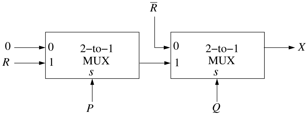
Two cascaded 2-to-1 multiplexers: the first has input 0 tied to 0, input 1 connected to R and select line P; its output feeds input 1 of the second, whose input 0 is R-bar and whose select line is Q; the output of the second MUX is X

The minimal sum of products form of the output \(X\) is

Exam Year(s)

GATE CS - 2016,

Answer: D

The output is \(X = \bar{Q}\bar{R} + PQR\).

A 2-to-1 MUX outputs input 0 when its select line is 0 and input 1 when it is 1. The first MUX outputs 0 when \(P = 0\) and \(R\) when \(P = 1\), so its output is \(PR\). The second MUX outputs \(\bar{R}\) when \(Q = 0\) and the first MUX's output \(PR\) when \(Q = 1\):

\[ X = \bar{Q}\bar{R} + Q(PR) = \bar{Q}\bar{R} + PQR \]

The two terms cannot be merged (one needs \(Q = 0\), the other \(Q = 1\)), so this is already minimal. Test values rule out the others: for \(P = 1, Q = 0, R = 0\) the circuit gives \(X = \bar{R} = 1\), but \(\bar{P}\bar{Q} + PQR\) and \(PQ + \bar{P}\bar{Q}R\) both give 0; for \(P = 0, Q = 1, R = 1\) the circuit gives 0, but \(\bar{P}Q + QR\) gives 1.

Please log in or register to report this question.
2.

Consider a digital display system (DDS) shown in the figure that displays the contents of register X. A 16-bit code word is used to load a word in X, either from S or from R. S is a 1024-word memory segment and R is a 32-word register file. Based on the value of mode bit M, T selects an input word to load in X. P and Q interface with the corresponding bits in the code word to choose the addressed word. Which one of the following represents the functionality of P, Q, and T?

(Figure: the code word has three fields, M, S-address and R-address. The S-address field feeds P, whose output goes to S; the R-address field feeds Q, whose output goes to R. The outputs of S and R are the two inputs of T, and M is connected to T. The output of T goes to X, which feeds the DDS.)

Exam Year(s)

GATE CS - 2022,

Answer: C

P is a 10:\(2^{10}\) decoder, Q is a 5:\(2^{5}\) decoder and T is a 2:1 multiplexer.

S holds 1024 = \(2^{10}\) words, so its address field has 10 bits, and P must turn those 10 bits into one select line out of 1024: that is a 10-to-\(2^{10}\) decoder. R holds 32 = \(2^{5}\) words, so Q turns 5 address bits into one of 32 select lines, a 5-to-\(2^{5}\) decoder. T has two data inputs, the word from S and the word from R, and the mode bit M chooses which one is passed to X; choosing one of two inputs under a select signal is a 2:1 multiplexer.

A 10:1 multiplexer picks one of ten inputs, which does not address 1024 words. An encoder converts one active line into a code, which is not what T does. A 1:10 de-multiplexer routes one input to ten outputs, again not an address decoder for 1024 locations.

Please log in or register to report this question.
3.

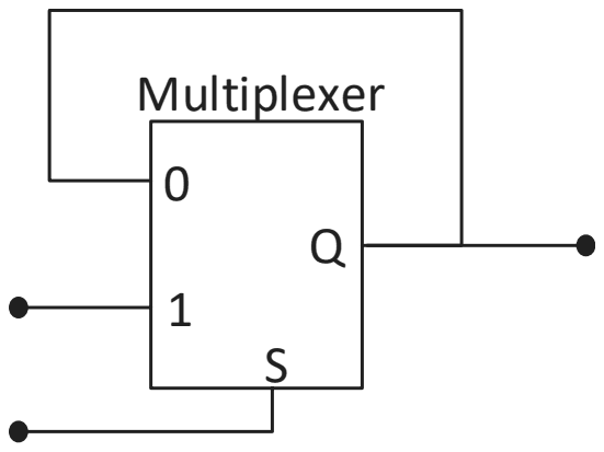
The output of a 2-input multiplexer is connected back to one of its inputs as shown in the figure.

A 2-input multiplexer whose output Q is fed back to its input 0, with input 1 and select line S as external inputs

Match the functional equivalence of this circuit to one of the following options.

Exam Year(s)

GATE CS - 2023,

Answer: B

The circuit is equivalent to a D latch.

The output Q is fed back to input 0, the external data line goes to input 1, and S selects between them:

  • S = 1: Q follows input 1, so the output tracks the data while S is high (the latch is transparent).
  • S = 0: Q takes input 0, which is Q itself, so the output holds its last value.

Following the data while an enable is high and holding it while the enable is low is a level-sensitive D latch, with S as the enable. A D flip-flop changes only on a clock edge, which needs two latches in a master-slave arrangement. A half-adder has two outputs, sum and carry, and no memory, and a demultiplexer routes one input to one of several outputs.

Please log in or register to report this question.
4.

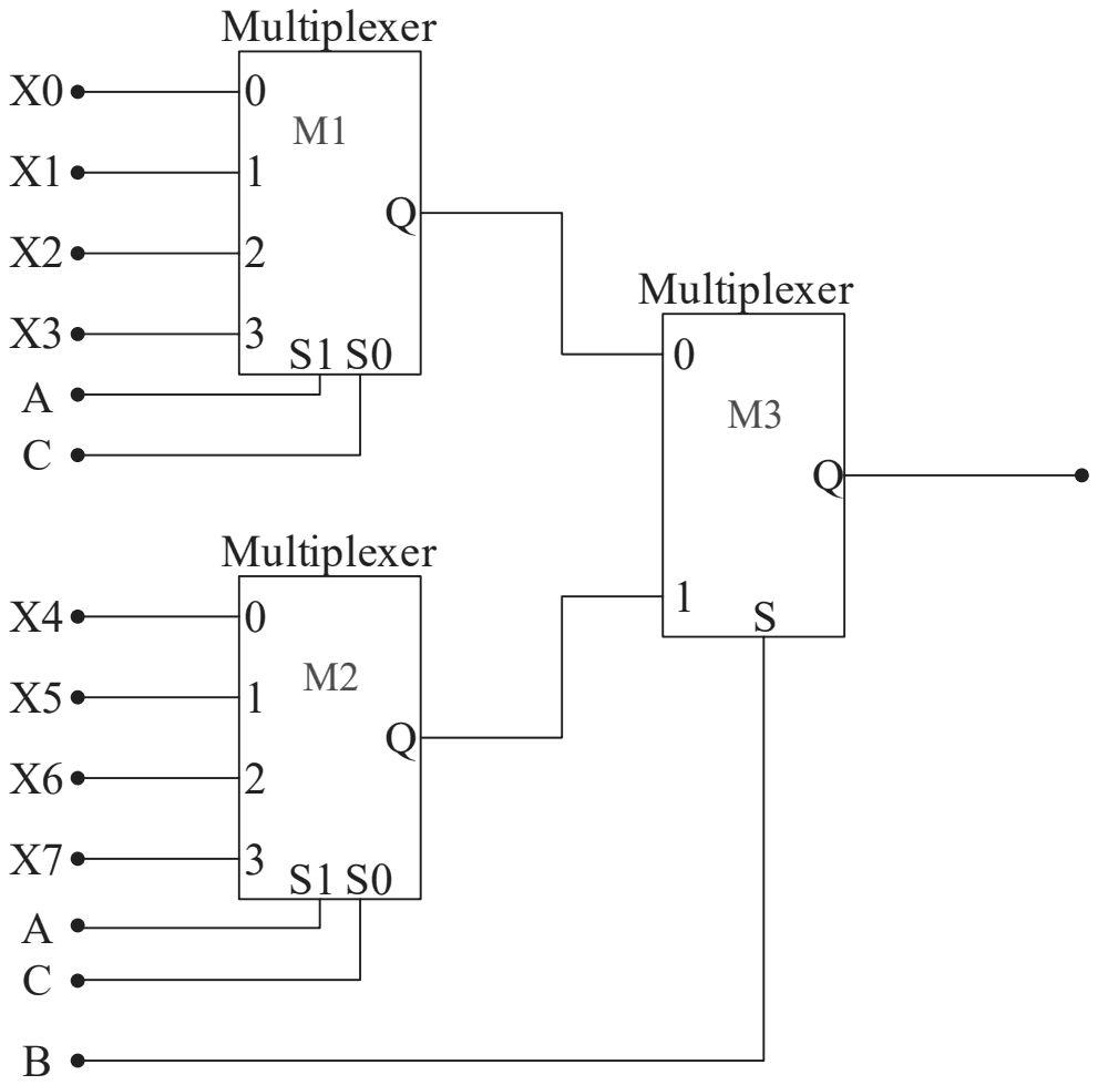
A Boolean digital circuit is composed using two 4-input multiplexers (M1 and M2) and one 2-input multiplexer (M3) as shown in the figure. X0-X7 are the inputs of the multiplexers M1 and M2 and could be connected to either 0 or 1. The select lines of the multiplexers are connected to Boolean variables A, B and C as shown.

M1 takes X0 to X3 and M2 takes X4 to X7, both with select lines S1 = A and S0 = C; their outputs feed inputs 0 and 1 of M3, whose select line is B

Which one of the following set of values of (X0, X1, X2, X3, X4, X5, X6, X7) will realise the Boolean function \(\overline{A} + \overline{A}.\overline{C} + A.\overline{B}.C\)?

Exam Year(s)

GATE CS - 2023,

Answer: C

The inputs are (1, 1, 0, 1, 1, 1, 0, 0).

First simplify the function. \(\overline{A}.\overline{C}\) is already covered by \(\overline{A}\), and \(\overline{A} + A.\overline{B}.C = \overline{A} + \overline{B}.C\):

\[ F = \overline{A} + \overline{B}C \]

M3 chooses M1 when B = 0 and M2 when B = 1. Both 4-input multiplexers select their input by (S1, S0) = (A, C).

  • B = 0: F = \(\overline{A} + C\). AC = 00, 01, 10, 11 gives X0..X3 = 1, 1, 0, 1.
  • B = 1: F = \(\overline{A}\). AC = 00, 01, 10, 11 gives X4..X7 = 1, 1, 0, 0.

The first option puts 0 in X3 and 1 in X6, the second puts 0 in X3 and 1 in X7, and the last sets X0 and X1 to 0, although F = 1 whenever A = 0.

Please log in or register to report this question.
5.

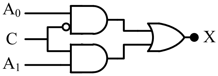
In a 2-to-1 multiplexer as shown below, the output X = A0 if C = 0, and X = A1 if C = 1.

(Figure: a block with data inputs A0 and A1, select input C and output X.)

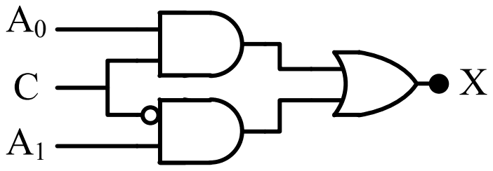
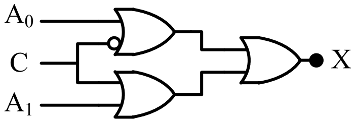
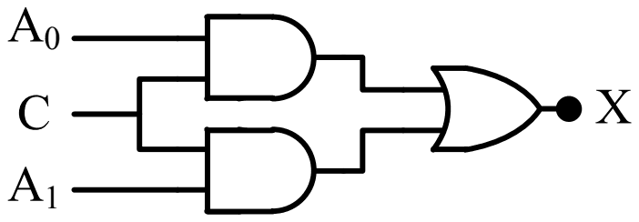
Which one of the following is the correct implementation of this multiplexer?

Exam Year(s)

GATE Physics - 2018,

Answer: A

The correct implementation is circuit (A).

A 2-to-1 multiplexer computes

\[ X = A_{0}\bar{C} + A_{1}C \]

so one AND gate must pass \(A_{0}\) when \(C = 0\), which needs \(C\) inverted at that gate, and the other must pass \(A_{1}\) when \(C = 1\), with \(C\) uninverted. An OR gate combines them. Circuit (A) has the inversion bubble on the \(C\) input of the \(A_{0}\) gate: exactly this.

Circuit (B) inverts \(C\) at the \(A_{1}\) gate, so it selects \(A_{1}\) when \(C = 0\), the reverse of the specification. Circuit (D) has no inversion, so both gates are enabled together by \(C = 1\) and both disabled by \(C = 0\). Circuit (C) uses OR gates in the first stage, which pass a 1 whenever either input is 1, so it cannot select one input.

Please log in or register to report this question.
6.

A circuit which is used to sent data from two or more sources through a single transmission line is known as :

Exam Year(s)

MH SET - 2018, SET Exam - 2018,

Answer: B

The circuit is a Multiplexer.

A multiplexer (data selector) has several data inputs, a set of select lines and one output. The select lines choose which input is passed to the single output line, so data from two or more sources can share one transmission line, in turn.

A de-multiplexer does the reverse, distributing one input line to several outputs. A decoder converts an n-bit code into one of \(2^{n}\) output lines, and an encoder converts one active input line into a binary code; neither puts several sources onto one line.

Please log in or register to report this question.
7.

Decimal to BCD priority encoder, 74147 will have :

Exam Year(s)

MH SET - 2019, SET Exam - 2019,

Answer: C

The 74147 has 10 inputs and 4 outputs.

The 74147 is the standard decimal-to-BCD priority encoder, described in data sheets as a 10-line to 4-line encoder: it encodes the ten decimal digits 0-9 into a 4-bit BCD code. Only nine input pins are actually provided, for 1 to 9, because the zero condition is represented when no input is active; inputs and outputs are active low, and the highest-numbered active input takes priority.

BCD needs exactly 4 output bits, so options with 8 outputs are wrong, and '8 inputs and 4 outputs' describes an octal-to-binary encoder such as the 74148.

Please log in or register to report this question.

Answer: A

A demultiplexer is called a data distributor because the input is distributed to one of the outputs.

A demultiplexer has one data input, several outputs and select lines. The select code decides which output receives the input data, so a single line of data can be distributed to any of several destinations.

Selecting one of several inputs for a single output is what a multiplexer (data selector) does. 'The output is distributed to one of the inputs' reverses the direction of data flow, and buffering is not what the name refers to.

Please log in or register to report this question.

9.

Multiplexer facilitates the following conversion :

Exam Year(s)

MH SET - 2021, SET Exam - 2021,

Answer: B

A multiplexer converts multiple inputs to a single output.

A multiplexer (data selector) has 2n data inputs, n select lines and one output. The binary number on the select lines chooses which input is routed to the output, so many data channels can share one line.

Routing a single input to one of several outputs is the opposite function, performed by a demultiplexer. Decimal-to-hexadecimal conversion is the job of an encoder or code converter, and parity conversion is done with exclusive-OR gates, not by a multiplexer.

Please log in or register to report this question.

Answer: C

The LED is on for \(\bar{C}\bar{B}A + \bar{C}BA + C\bar{B}\bar{A} + CB\bar{A}\).

The decoder outputs are active-low, and y0, y2, y5 and y7 feed the NAND gate. A NAND of active-low signals acts as an OR of the selected minterms, so

\[ F = m_{0} + m_{2} + m_{5} + m_{7} \]

The LED has its anode at +VCC and its cathode at F, so it lights only when F is LOW, that is for the remaining minterms m1, m3, m4 and m6. With C as the most significant bit these are 001, 011, 100 and 110, the four terms of the third option.

The other options include terms such as CBA (m7) or \(\bar{C}B\bar{A}\) (m2), for which F is HIGH and the LED is off.

Please log in or register to report this question.

Loading…
Tags: Multiplexers and Decoders Questions and Answers || Multiplexers and Decoders MCQ Questions and Answers || Multiplexers and Decoders GK Questions and Answers || Multiplexers and Decoders GK MCQ Questions || Multiplexers and Decoders Multiple Choice Questions and Answers || Multiplexers and Decoders GK || GK on Multiplexers and Decoders || Digital Electronics Questions and Answers || Digital Electronics MCQ Questions and Answers || Digital Electronics GK Questions and Answers || GK on Digital Electronics