
Machine-translated by Google. Questions are authored in English.
Top

Combinational Logic Circuits Questions and Answers

Direction for [ Question No: 1 To 1 ] :

Assertion - Reason type questions : The following items consist of two statements, one labelled the 'Assertion (A)' and the other labelled the 'Reason (R)'. You are to examine these two statements and decide if the Assertion (A) and the Reason (R) are individually true and if so, whether the Reason is a correct explanation of the Assertion. Select your answers to these items using the codes given below and mark your answer sheet accordingly.

1.

Assertion (A) : A half-adder is faster than full-adder.
Reason (R) : A half-adder gives only one output while a full adder gives two outputs.

Exam Year(s)

UGC NET - 2013,

Answer: C

A half adder is simpler and has fewer gates in the path, so it is faster than a full adder, and (A) is true. (R) is false, since a half adder gives two outputs, sum and carry, as does a full adder. So (R) is false and cannot explain (A). A full adder must add the carry coming from the previous stage as well, so its signal passes through two half-adder stages and an OR gate, and it is slower, not faster. That the half adder is faster is true, but the stated reason for it is wrong, so the reason cannot be the explanation. The answer is (A) is true and (R) is false.

Please log in or register to report this question.

Direction for [ Question No: 2 To 2 ] :

Directions : The following items consist of two statements, one labelled the "Assertion" (A) and other labelled the "Reason" (R). You are to examine these two statements carefully and decide if the Assertion (A) and the Reason (R) are individually true and if so, whether the Reason is a correct explanation of the Assertion. Select your answers to these items using the codes given below and mark your answer accordingly.

2.

Assertion (A) : Combinational circuits have no memory, timing or feed back loop.

Reason (R) : The output of combinational circuit depends on their input and previous output state.

Exam Year(s)

UGC NET - 2013,

Answer: C

The assertion is true and the reason is false, which is option (C). A combinational circuit has no memory, timing or feedback loop, so its output depends only on the present inputs. The reason adds the previous output state, which describes a sequential circuit. Hence (A) and (B) are wrong because they accept the reason, and (D) is wrong because the assertion is true.

Please log in or register to report this question.
Direction for [ Question No: 3 To 3 ] :

Directions : Q. Nos. 21 to 30 : The following items consist of two statements, one labelled the “Assertion (A)” and the other labelled the “Reason (R)”. You are to examine these two statements carefully and decide if the Assertion (A) and the Reason (R) are individually true and if so, whether the Reason is a correct explanation of the Assertion. Select your answers to these items using the codes given below and mark your answer accordingly.

3.

Assertion (A) : An half adder is faster than full-adder.

Reason (R) : An half adder gives only one output while a full adder gives two outputs.

Exam Year(s)

UGC NET - 2012,

Answer: C

The keyed answer is (A) true and (R) false. A half adder has a single gate delay for each output, an XOR for the sum and an AND for the carry, whereas a full adder has to combine three inputs, so the half adder is faster and (A) is true. The reason claims that the half adder gives only one output while the full adder gives two, which is wrong: both circuits have two outputs, a sum and a carry. Hence (R) is false and option C is correct.

Please log in or register to report this question.

4.

For a full-scale voltage of \(0 - 3\) V, the resolution of the 4-bit ADC is ______.

Exam Year(s)

DSSSB AE - 2023,

Answer: B

The resolution (the size of one step) of an n-bit ADC is the full scale range divided by \(2^n - 1\) steps.


\[ \begin{aligned} \text{Resolution} = \frac{3\ \text{V}}{2^4 - 1} \\ &= \frac{3}{15} = 0.2\ \text{V} = 200\ \text{mV} \end{aligned} \]


Dividing by 16 instead of 15 would give 187.5 mV, which is not offered, so 200 mV is the intended answer. The values 100, 300 and 400 mV would be 3 V divided by 30, 10 and 7.5, which do not correspond to a 4-bit converter. The answer is option B.

Please log in or register to report this question.

5.

What is the value of analogue output voltage Vo, for an N-bit straight binary digital to analogue converter, for the input 0010? The value of proportionality factor K is 1.

Exam Year(s)

DSSSB AE - 2023,

Answer: C

For an N bit straight binary digital to analogue converter the output voltage is the proportionality factor times the decimal value of the binary input.


\[ V_o = K \times (\text{decimal value of input}) \]


The binary input 0010 is 2 in decimal (the bit with weight \(2^1\) is set), and \(K = 1\), so


\[ V_o = 1 \times 2 = 2\ \text{V} \]


The value 1 would be for the input 0001, and 3 for 0011, and 0 for 0000. The answer is 2, option C.

Please log in or register to report this question.
6.

The "carry look ripple delay" is eliminated in :

Exam Year(s)

MH SET - 2018, SET Exam - 2018,

Answer: B

The carry ripple delay is eliminated in the carry-look-ahead adder circuit.

In a ripple-carry parallel adder each full adder must wait for the carry from the stage below, so the delay grows with the number of bits. A carry-look-ahead adder computes generate \(G_{i} = A_{i}B_{i}\) and propagate \(P_{i} = A_{i} \oplus B_{i}\) for each bit and then forms every carry directly from them and the input carry:

\[ C_{i+1} = G_{i} + P_{i}C_{i} \]

expanded so that all carries appear after a fixed number of gate delays. An ordinary parallel adder is the ripple-carry circuit that has the delay, and a single full adder or half adder (printed 'Haff-adder') handles one bit and does nothing about ripple.

Please log in or register to report this question.

7.

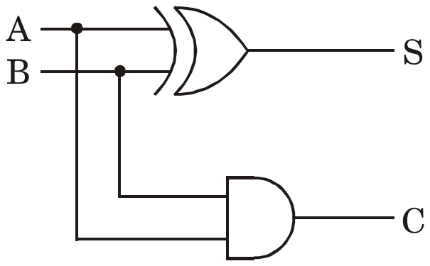
The correct circuit of a Half Adder is :

Exam Year(s)

MH SET - 2019, SET Exam - 2019,

Answer: B

The correct half adder is circuit (B): an XOR gate gives the sum S and an AND gate gives the carry C.

A half adder adds two single bits A and B. The truth table is 0+0 = 00, 0+1 = 01, 1+0 = 01 and 1+1 = 10, written as carry and sum. The sum bit is 1 only when exactly one input is 1, which is A XOR B. The carry bit is 1 only when both inputs are 1, which is A AND B:

\[ S = A \oplus B \]

\[ C = A \cdot B \]

Circuit (A) swaps the two gates, so it gives the wrong sum and carry. Circuit (C) uses an OR gate for the sum, which gives 1 for 1+1 where the sum should be 0. Circuit (D) uses NAND and NOR gates, which are the complements of AND and OR, so it is not an adder either.

Please log in or register to report this question.

8.

Match the List-I with List-II and select the correct answer using the codes given below the lists :

List-IList-II
(a) ALU(i) EXOR-Gate
(b) Parity checker(ii) Full adder
(c) Shift register(iii) MOS Transistor
(d) DRAM(iv) DFF

Exam Year(s)

MH SET - 2019, SET Exam - 2019,

Answer: D

The correct matching is a-ii, b-i, c-iv, d-iii.

  • (a) An ALU performs addition with full adders (ii).
  • (b) A parity checker is built from EXOR gates, whose output reveals an odd number of 1s (i).
  • (c) A shift register is a chain of D flip-flops (iv).
  • (d) A DRAM cell stores a bit as charge on a capacitor accessed by one MOS transistor (iii).

Each other code gives the EXOR gate, the D flip-flop or the MOS transistor to the wrong block.

Please log in or register to report this question.

9.

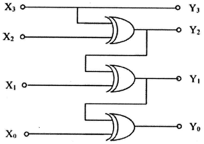
The binary output Y3 Y2 Y1 Y0 of the following logic circuit for the inputs X3 X2 X1 X0 = 1 0 1 1 is :

Y3 is X3; Y2 is the output of an XOR gate fed by X3 and X2; Y1 is the output of an XOR gate fed by Y2 and X1; Y0 is the output of an XOR gate fed by Y1 and X0

Exam Year(s)

MH SET - 2024, SET Exam - 2024,

Answer: A

The output is 1 1 0 1.

The circuit is a Gray-to-binary converter: \(Y_{3} = X_{3}\), and each lower bit is the XOR of the next higher output bit with the corresponding input:

  • \(Y_{3} = X_{3} = 1\)
  • \(Y_{2} = Y_{3} \oplus X_{2} = 1 \oplus 0 = 1\)
  • \(Y_{1} = Y_{2} \oplus X_{1} = 1 \oplus 1 = 0\)
  • \(Y_{0} = Y_{1} \oplus X_{0} = 0 \oplus 1 = 1\)

Feeding each XOR with neighbouring input bits instead (binary-to-Gray) would give 1 1 1 0, which is not offered. 1 0 1 0 and 0 1 0 1 do not satisfy \(Y_{3} = X_{3} = 1\) together with the XOR chain.

Please log in or register to report this question.

10.

A circuit implements the logic expression \(F = (A \oplus B)' \cdot (A + C')\). The number of distinct logic levels (gate delays) in the minimal implementation is

Exam Year(s)

Tripura Public Service Commission - 2026,

Answer: D

The keyed answer is 3.

Simplify with the identity \((A \oplus B)' = AB + A'B'\):

\[ F = (AB + A'B')(A + C') \]\[ = AB + ABC' + A'B'A + A'B'C' \]\[ = AB + A'B'C' \]

The minimal form is a two-term AND-OR circuit. Built from basic gates, the complemented inputs A', B' and C' need NOT gates first, so the signal passes through a NOT gate, an AND gate and an OR gate: three levels of gate delay. Option 4 over-counts and option 1 is impossible for a function of three variables that is not a single gate.

If complemented inputs were assumed to be available for free, the same circuit would have two levels, so the question depends on counting the input inverters; the key counts them.

Please log in or register to report this question.

Loading…

Other Subjects

Tags: Combinational Logic Circuits Questions and Answers || Combinational Logic Circuits MCQ Questions and Answers || Combinational Logic Circuits GK Questions and Answers || Combinational Logic Circuits GK MCQ Questions || Combinational Logic Circuits Multiple Choice Questions and Answers || Combinational Logic Circuits GK || GK on Combinational Logic Circuits || Digital Electronics Questions and Answers || Digital Electronics MCQ Questions and Answers || Digital Electronics GK Questions and Answers || GK on Digital Electronics