Machine-translated by Google. Questions are authored in English.
Top

Frequency Response of Amplifiers Questions and Answers

1.

An input voltage in the form of a square wave of frequency 1 kHz is given to a circuit, which results in the output shown schematically below. Which one of the following options is the CORRECT representation of the circuit?
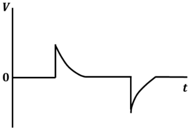
Output voltage against time: zero, a sharp positive spike that decays back to zero, then a sharp negative spike that decays back to zero

Exam Year(s)

GATE Physics - 2023,

Answer: A

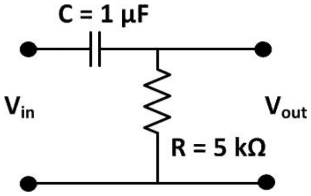
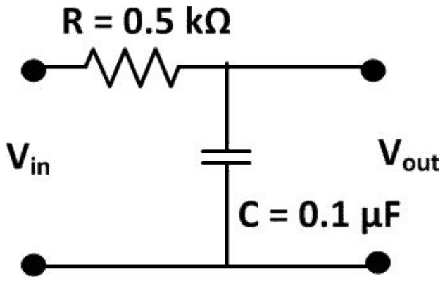
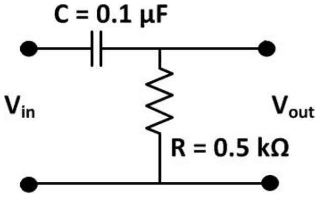
The circuit is (A): a series 0.1 μF capacitor with a shunt 0.5 kΩ resistor, a differentiator with a short time constant.

The output is a sharp spike at each edge of the square wave that dies away to zero long before the next edge. That is the response of a high-pass RC circuit (capacitor in series, output across the resistor) whose time constant is much shorter than the half period.

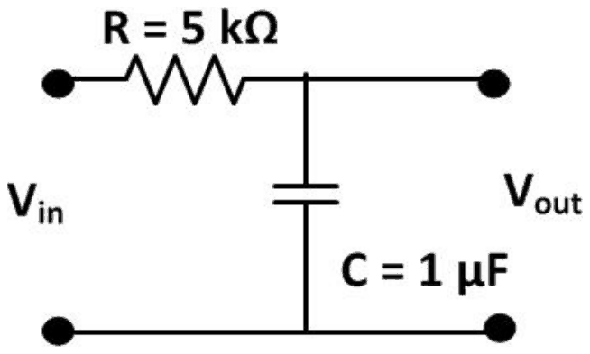
\[ \begin{aligned} \tau_{A} &= 0.5\ \text{k}\Omega \times 0.1\ \mu\text{F} = 50\ \mu\text{s} \\ T/2 &= 0.5\ \text{ms} \end{aligned} \]

With \(\tau \ll T/2\) each spike decays fully, as drawn. Circuit (B) has the same layout but \(\tau = 5\) ms, ten times the half period, so its output would barely decay and look like a slightly tilted square wave. Circuits (C) and (D) take the output across the capacitor; these low-pass integrators give smoothed or ramp-like versions of the square wave, not spikes.

Please log in or register to report this question.

2.

Steady state response of an electric circuit is generally tested by giving following waveform at the input :

Exam Year(s)

MH SET - 2018, SET Exam - 2018,

Answer: A

The steady state response is tested with a sinusoidal input.

A linear circuit driven by a sinusoid settles, after the transients die out, into a sinusoid of the same frequency, changed only in amplitude and phase. Measuring that change over a range of frequencies gives the circuit's steady state (frequency) response, and any other periodic input can be built from sinusoids by Fourier analysis.

Square, triangular and sawtooth waves contain many harmonics at once. A square wave is the usual test for the transient response, such as rise time and overshoot, rather than for the steady state, and the others are used mainly for sweep and ramp testing.

Please log in or register to report this question.

Answer: A

The ascending order is dc amplifier, audio amplifier, radio amplifier, video amplifier.

Bandwidths grow in this order. A dc amplifier is usually meant for slowly varying signals, with a bandwidth from 0 Hz up to a few hundred hertz or kilohertz. An audio amplifier covers about 20 Hz to 20 kHz. A radio-frequency (tuned) amplifier passes a band of the order of tens to hundreds of kilohertz around its carrier. A video amplifier must pass about 0 Hz to several megahertz.

The other options put the video amplifier first or in the middle, or the dc amplifier after the radio amplifier, which does not match these bandwidths.

Please log in or register to report this question.

Direction for [ Question No: 4 To 4 ] :

Directions : Q. Nos. 61 to 70, the following items consist of two statements, one labelled the "Assertion (A)" and the other labelled the "Reason (R)". You are to examine these two statements carefully and decide if the Assertion (A) and the Reason (R) are individually true and if so, whether the Reason (R) is a correct explanation of the Assertion (A). Select your answers to these items using the codes given below and mark your answer accordingly.

4.

Assertion (A) : In amplifiers, it is easy to compare two powers on a Logarithmic rather than on linear scale. It is called decibel.

Reason (R) : Decibel is defined as \(N = 10 \log \dfrac{P_2}{P_1}\), where \(P_2\) is output power and \(P_1\) is input power.

Exam Year(s)

UGC NET - 2013,

Answer: A

Both statements are correct and the reason explains the assertion, the first option. In amplifiers the powers can differ by a very large factor, so comparing them on a logarithmic scale is convenient, and the unit of that scale is the decibel.

The reason supplies the definition \(N = 10 \log (P_2/P_1)\) with \(P_2\) the output and \(P_1\) the input power, which is exactly what makes the decibel a logarithmic comparison. So it is a correct explanation, and the options that deny this are wrong.

Please log in or register to report this question.

Answer: A

The low end is set by capacitors in series with the signal, or in parallel with a degeneration resistor, whose reactance grows as the frequency falls until they no longer pass or bypass. Junction and stray capacitances shunt the signal away and so act at the high end instead. The collector resistor sets gain rather than a break frequency. Whether a capacitance is in series or in shunt with the signal path decides which end of the response it governs, and that single distinction accounts for the whole shape of a Bode plot.

Please log in or register to report this question.

Answer: B

The high end is set by capacitances in parallel with the signal - the junction capacitances, the Miller-multiplied collector-base capacitance, and stray wiring capacitance - which divert an increasing share of the signal current as frequency rises. Series coupling capacitors and emitter bypasses act at the low end, and supply decoupling is not in the signal path at all. A shunt path that improves with frequency always produces a high-frequency roll-off, whatever the circuit.

Please log in or register to report this question.

Answer: C

Reactance is inversely proportional to frequency, so at low enough frequencies the capacitor's reactance is no longer small beside the series resistance and it drops an appreciable part of the signal. Leakage, charging behaviour and dielectric loss are all real properties but none produces the roll-off. The break occurs where reactance equals resistance, which is why the break frequency contains the product of the two and nothing else.

Please log in or register to report this question.

Answer: D

The break is defined where the reactance equals the resistance, which makes the total impedance root two times the resistance and the gain 3 dB down. That equality is what gives the familiar expression with two pi, the frequency, the resistance and the capacitance all in one product. Doubling or halving would put the break at a different frequency, and a squared relation is dimensionally impossible. Every break frequency in this topic comes from setting one impedance equal to another.

Please log in or register to report this question.

9.

How much is the gain down at a single break frequency?

Answer: A

At the break the gain is 3 dB below its passband value, a factor of about 0.707 in voltage, and the phase has shifted forty-five degrees. Six decibels per octave is the slope beyond the break rather than the drop at it, twenty decibels per decade is the same slope expressed differently, and one decibel is not a standard figure here. Confusing the drop at the break with the slope after it is the commonest error in reading these responses, and the two are quite separate quantities.

Please log in or register to report this question.

10.

What phase shift does a single pole contribute at its break frequency?

Answer: B

At the break the phase is forty-five degrees, on its way to ninety degrees well beyond it. Zero applies well inside the passband and one hundred and eighty would require two poles, which is exactly why stability analysis counts poles so carefully. Attaching each phase figure to its position relative to the break, rather than learning the three as a bare list, is what makes them usable when a feedback loop's margin has to be assessed.

Please log in or register to report this question.

Loading…

Other Subjects

Tags: Frequency Response of Amplifiers Questions and Answers || Frequency Response of Amplifiers MCQ Questions and Answers || Frequency Response of Amplifiers GK Questions and Answers || Frequency Response of Amplifiers GK MCQ Questions || Frequency Response of Amplifiers Multiple Choice Questions and Answers || Frequency Response of Amplifiers GK || GK on Frequency Response of Amplifiers || Analog Electronics Questions and Answers || Analog Electronics MCQ Questions and Answers || Analog Electronics GK Questions and Answers || GK on Analog Electronics