
Machine-translated by Google. Questions are authored in English.
Top

BJT Biasing and Stability Questions and Answers

101.

With that Thevenin resistance and a base voltage of \( 2 \ \mathrm{V} \) from a \( 12 \ \mathrm{V} \) supply, the two divider resistors are about

Answer: A

The ratio fixes their proportion and the parallel value fixes their size:

\[ \begin{aligned} \frac{R_{2}}{R_{1}+R_{2}} &= \frac{2}{12} \\ R_{1} \| R_{2} &= 15 \ \mathrm{k\Omega} \end{aligned} \]

which gives about 90 k and 18 k, the larger arm to the supply. Reversing them would put the base at ten volts. Two conditions determine two unknowns, and setting both up before solving avoids the guesswork.

Please log in or register to report this question.

Answer: B

A stiff divider is a voltage source, so the base voltage is what it holds constant, and the emitter resistor then converts that into a current. The base current is whatever the device happens to draw and is exactly the beta-dependent quantity the arrangement is avoiding. Specifying the quantity a circuit actually controls, rather than one that follows from it, is what keeps a design's assumptions visible.

Please log in or register to report this question.
Answer: C

The emitter current is set by the base voltage and the emitter resistor, so almost nothing changes - only a very slight rise as the reduced base current loads the divider a little less. Doubling the collector current is what fixed bias would do. The stage certainly does not saturate, and the base voltage rise is real but tiny. That a design's behaviour survives a twofold change in its least reliable parameter is the practical test of whether it is beta-independent.

Please log in or register to report this question.
Answer: D

The emitter voltage divided by the emitter resistor gives the collector current directly, which is the quantity the design specifies. The base-emitter drop is nearly always about 0.7 V and says little, in-circuit resistance measurements are unreliable, and total supply current includes the divider. Choosing the measurement that converts in one step into the designed quantity is worth a moment's thought before any probe is placed.

Please log in or register to report this question.

105.

For the given circuit, find the collector current \(I_C\), if \(\beta = 100\) and \(V_{BE} = 0.7\) V.

Transistor circuit: supply +15 V, base divider R1 6 kilohm to the supply and R2 3 kilohm to ground, collector resistor RC 470 ohm, emitter resistor RE 1 kilohm with a bypass capacitor CE

Exam Year(s)

DSSSB AE - 2023,

Answer: B

Use the Thevenin equivalent of the base divider, with \(V_{CC} = 15\) V, \(R_1 = 6\ \text{k}\Omega\) and \(R_2 = 3\ \text{k}\Omega\).


\[ \begin{aligned} V_{TH} = 15 \times \frac{3}{6 + 3} \\ &= 5\ \text{V},\qquad R_{TH} = 6 \parallel 3 \\ &= 2\ \text{k}\Omega \end{aligned} \]


The base loop equation with \(I_E = (\beta + 1) I_B\) is


\[ 5 = I_B R_{TH} + 0.7 + (\beta + 1) I_B R_E \]


\[ \begin{aligned} I_B = \frac{4.3}{2 + 101 \times 1}\ \text{mA} \\ &= 0.0417\ \text{mA} \end{aligned} \]


\[ \begin{aligned} I_C = \beta I_B = 100 \times 0.0417 \\ &= 4.17 \approx 4.2\ \text{mA} \end{aligned} \]


The answer is 4.2 mA, option B. The other values are off by a factor of ten.

Please log in or register to report this question.

106.

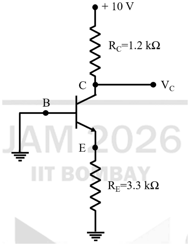
Consider the circuit of the figure, the voltage Vc , in Volts, is:

npn transistor with base B connected to ground; collector C connected to +10 V through RC = 1.2 kilohm with VC taken at the collector; emitter E connected to ground through RE = 3.3 kilohm

Exam Year(s)

IIT JAM - 2026,

Answer: D

\(V_C\) is 10 V.

For an npn transistor to conduct, its base-emitter junction must be forward biased by about 0.7 V, with the base above the emitter. Here the base is tied to ground (0 V) and the emitter returns to ground through \(R_E\), with no negative supply. The emitter can never be pulled below 0 V, so \(V_{BE} \le 0\) and the transistor is cut off.

With no collector current there is no drop across \(R_C\):

\[ V_C = 10 - I_C R_C = 10 - 0 = 10\ \text{V} \]

0 V would describe a short to ground, and 9.8 V or 1.25 V would need a collector current to flow, which assumes the transistor is biased on. The values of \(R_C\) and \(R_E\) do not enter at all.

Please log in or register to report this question.

107.

A circuit with a fixed emitter current is called :

Exam Year(s)

RSMSSB JE - 2025, RSMSSB - 2025,

Answer: A

The circuit is called emitter bias.

In emitter bias the base is held at a fixed voltage and a resistor \(R_{E}\) is placed in the emitter, so \(I_{E} \approx (V_{B} - V_{BE})/R_{E}\). The emitter current is set by the circuit values and is almost independent of \(\beta\), which is why it is described as fixing the emitter current.

Base bias, by contrast, fixes the base current, so the collector current changes with β. Two-supply bias is one way of building emitter bias, not the general name, and 'transistor bias' is just a general term for any biasing method.

Please log in or register to report this question.

108.

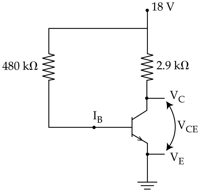
For the fixed bias configuration of BJT as shown in figure of silicon BJT having ratio of collector current to base current (β) equal to 95, what will be the value of VCE ?

Fixed bias circuit: an 18 V supply feeds the base through a 480 kilohm resistor with base current IB and the collector through a 2.9 kilohm resistor; the emitter is grounded and VCE is marked between collector and emitter

Exam Year(s)

RSMSSB JE - 2025, RSMSSB - 2025,

Answer: B

VCE works out to about 8.08 V.

In the fixed-bias circuit the base current comes from the 18 V supply through the 480 kΩ resistor, less the 0.7 V base-emitter drop of a silicon transistor. The collector current is β times that, and VCE is the supply minus the drop across the 2.9 kΩ collector resistor.

\[ \begin{aligned} I_{B} &= \frac{18 - 0.7}{480\ \text{k}\Omega} \approx 36\ \mu\text{A} \\ I_{C} &= 95 \times 36\ \mu\text{A} = 3.42\ \text{mA} \end{aligned} \]

\[ \begin{aligned} V_{CE} &= 18 - 3.42\ \text{mA} \times 2.9\ \text{k}\Omega \\ &= 18 - 9.92 = 8.08\ \text{V} \end{aligned} \]

Carrying more decimal places gives 8.07 V, so 8.08 V is the option the working lands on. Leaving out the 0.7 V drop gives about 7.67 V, and 7 V and 8 V are round figures that do not follow from the circuit values.

Please log in or register to report this question.

109.

For the following transistor circuit assume \(V_{BE} = 0.7\) V, \(\beta_{dc} = 100\); then the current flowing through \(R_{E}\) is :

NPN transistor: collector to +VCC = 15.0 V through RC = 1.5 kOhm, base to ground through RB = 1.0 kOhm, emitter to -VEE = 5.0 V through RE = 1.0 kOhm

Exam Year(s)

MH SET - 2023, SET Exam - 2023,

Answer: C

The emitter current is about 4.3 mA.

Go round the base-emitter loop from ground, through \(R_{B}\), across the base-emitter junction and through \(R_{E}\) to the -5.0 V supply:

\[ \begin{aligned} 5.0 - 0.7 &= I_{B}R_{B} + I_{E}R_{E} \\ I_{B} &= \frac{I_{E}}{\beta + 1} = \frac{I_{E}}{101} \end{aligned} \]

\[ \begin{aligned} 4.3 &= I_{E}\left(1.0 + \frac{1.0}{101}\right)\ \text{k}\Omega \\ I_{E} &= \frac{4.3}{1.0099} \approx 4.26\ \text{mA} \end{aligned} \]

which rounds to 4.3 mA. The transistor is in the active region: the collector sits at about 15 - 6.3 = 8.7 V, well above the emitter. 4.0 mA and 3.6 mA come from subtracting the drop across \(R_{B}\) as if \(I_{B}\) were much larger, and 8.0 mA would need the full 15 V across the emitter loop.

Please log in or register to report this question.

110.

In a CE configuration, an emitter resistor is used for ...............

Exam Year(s)

MH SET - 2024, SET Exam - 2024,

Answer: A

The emitter resistor is used for stabilization of the operating point.

If the collector current rises, for example because \(\beta\) or the temperature increases, the voltage across \(R_{E}\) rises with it. That reduces the base-emitter voltage, which reduces the base current and pulls the collector current back. This DC negative feedback keeps the Q-point steady against transistor variation and thermal runaway.

An emitter resistor does not bypass AC signals; the capacitor placed across it does that, so that the resistor stabilises DC without cutting the AC gain. It does not provide collector bias. Unbypassed, it actually reduces the gain, so 'higher gain' is the opposite of its effect.

Please log in or register to report this question.

Loading…
Tags: BJT Biasing and Stability Questions and Answers || BJT Biasing and Stability MCQ Questions and Answers || BJT Biasing and Stability GK Questions and Answers || BJT Biasing and Stability GK MCQ Questions || BJT Biasing and Stability Multiple Choice Questions and Answers || BJT Biasing and Stability GK || GK on BJT Biasing and Stability || Analog Electronics Questions and Answers || Analog Electronics MCQ Questions and Answers || Analog Electronics GK Questions and Answers || GK on Analog Electronics