
Machine-translated by Google. Questions are authored in English.
Top

Diode Circuits and Applications Questions and Answers

Answer: A

The rating that actually destroys the device is junction temperature, and thermal resistance is what converts dissipated power into the rise above ambient. The forward drop and leakage are measured at stated temperatures but are not what the figure is for, and the surge rating is a separate specification. Any thermal calculation works backwards from the limiting temperature through the resistances to the power that may be allowed, which is why the path is specified end to end.

Please log in or register to report this question.
102.

A diode dissipates \( 1 \ \mathrm{W} \) with a thermal resistance of \( 60 \ \mathrm{^\circ C/W} \) in a \( 40 \ \mathrm{^\circ C} \) ambient. Its junction reaches

Answer: B

Adding the rise to the ambient:

\[ T_{j} = 40 + (1 \times 60) = 100 \ \mathrm{^\circ C} \]

giving 100 degrees, safely below a silicon limit of 150 but leaving little margin for a hotter ambient. Sixty degrees is the rise alone and forty the ambient alone. Whether a device survives is decided by the sum rather than either term, which is why an ambient specification is as much part of a rating as the power figure.

Please log in or register to report this question.
103.

With a heatsink halving that thermal resistance, the same dissipation gives a junction temperature of

Answer: C

Halving the resistance halves the rise:

\[ T_{j} = 40 + (1 \times 30) = 70 \ \mathrm{^\circ C} \]

so 70 degrees, a thirty degree improvement bought entirely with metal. Fifty degrees would need a quarter of the original resistance. Because the rise is proportional to the resistance, halving one halves the other exactly, which makes heatsink sizing one of the more straightforward calculations in a power design.

Please log in or register to report this question.
Answer: D

Reverse saturation current roughly doubles for every ten degrees, so a device that leaks microamps at room temperature can leak milliamps when hot - and since that leakage dissipates power under reverse voltage, it can feed a thermal runaway. It does not reverse direction, remains largely independent of reverse voltage, and stays far below the forward current. Any mechanism whose effect grows with the temperature it produces has to be checked for runaway rather than merely tabulated.

Please log in or register to report this question.

Answer: A

Because sixty millivolts changes the current tenfold, setting a diode's current by applying a voltage is hopelessly imprecise, and the current must be set by a series element. The forward drop is easy to measure at a known current, leakage is measurable with care, and frequency is a separate matter. Every device with an exponential characteristic is driven from a current rather than a voltage for exactly this reason, which is why the same arrangement appears with light emitting diodes and transistor base junctions.

Please log in or register to report this question.

Answer: B

Differentiating the diode equation gives a slope resistance of the thermal voltage divided by the current, so at one milliamp it is about 26 ohms and at ten it is about 2.6. Bulk resistance, capacitance and stored charge are all real effects but none produces this relation. A current-controlled resistance falling as one over the current is what makes diodes and transistor junctions useful as variable elements, and the same expression reappears throughout small-signal analysis.

Please log in or register to report this question.

Answer: C

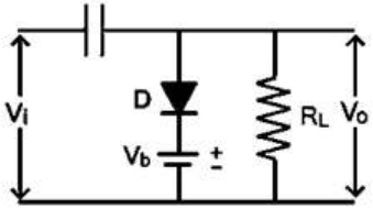
The circuit has a series capacitor, a shunt diode with a battery and the load across the output, which is the form of a clamper (a dc restorer) that shifts the level of the whole waveform without changing its shape.


In the figure the diode is placed so that it conducts when the output tries to go above the battery voltage. Once the capacitor charges during the first conducting interval, it holds the output peaks at the bias level, so the waveform is shifted down: this is a negative clamper. The battery is connected so that its positive terminal is on the diode side, so the clamping level is a positive voltage, and the circuit is a negative clamper with positive bias, option C.


A positive clamper would have the diode reversed so that the output bottoms out near the bias level instead.

Please log in or register to report this question.
108.

In a \(\pi\)-filter, the number of capacitors used are ______ and the number of inductors used are ______, respectively.

Exam Year(s)

DSSSB AE - 2023,

Answer: A

A \(\pi\)-filter (capacitor input filter) is named after the shape of its circuit: a shunt capacitor at the input, a series inductor (choke) in the middle and a second shunt capacitor at the output. So it uses two capacitors and one inductor, like the Greek letter pi with the inductor as the top bar and the two capacitors as the legs.


The first capacitor takes most of the ripple off the rectified output, and the choke and the second capacitor smooth what remains. The other options have too many inductors or the wrong numbers of parts. The answer is two capacitors and one inductor, option A.

Please log in or register to report this question.
109.

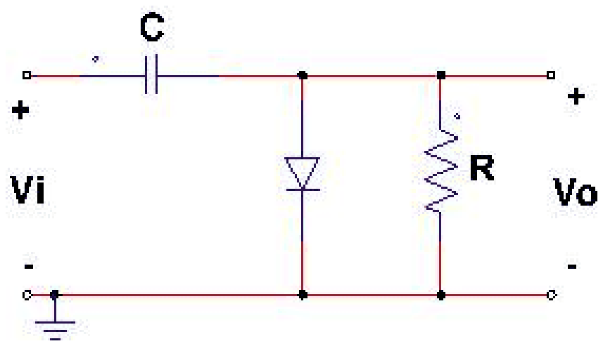
For the given clamper circuit, the diode is ideal.

Clamper circuit: input Vi through a series capacitor C, a diode D across the output to the ground line, and a resistor R across the output Vo

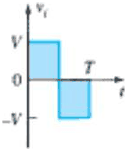
The input Vi is:

Input waveform Vi: a square wave that is +V for the first half period and -V for the second half period of T

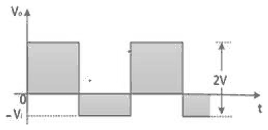
The output Vo is:

Exam Year(s)

DSSSB AE - 2023,

Answer: C

The capacitor in series charges through the diode, and the clamper shifts the dc level of the input without changing its shape. The diode is connected with its anode at the output node, so it conducts when the output tries to go positive. During the first half cycle (input \(+V\)) the diode conducts and the capacitor charges to \(V\), keeping the output at about 0 V. When the input falls to \(-V\) the diode is off and the output is the input minus the capacitor voltage, \(-V - V = -2V\).


So the output is a square wave between 0 and \(-2V\), which is figure (C). Figure (A) and (B) swing positive, so they would need the diode reversed, and figure (D) is the input itself without a shift. The answer is option C.

Please log in or register to report this question.
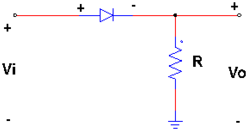
110.

For the given circuit, the diode is ideal.

Half-wave rectifier circuit: input Vi through a series diode, with a resistor R across the output Vo

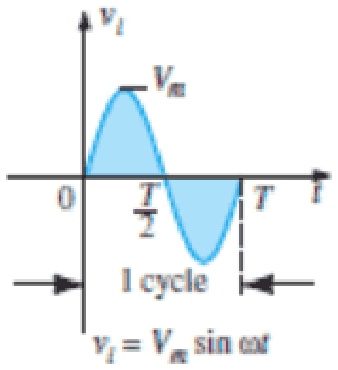
The input to this circuit is:

Input waveform Vi equals Vm sin(omega t), shown for one cycle from 0 to T with T/2 marked

The output voltage \(V_o\) from \(T/2\) to \(T\) will be:

Exam Year(s)

DSSSB AE - 2023,

Answer: A

The circuit is a half wave rectifier: the ideal diode is in series with the load resistor. The diode conducts when the anode is positive with respect to the cathode, that is during the positive half cycle (0 to \(T/2\)), when the output follows the input.


From \(T/2\) to \(T\) the input is negative, so the diode is reverse biased and acts as an open circuit. No current flows through \(R\), and so the output voltage \(V_o = iR = 0\). The output is zero, option A. The values \(V_m\) and \(V_m/2\) would be the output during the positive half, and \(-V_m\) would appear only if the diode were short circuited, but then it would appear across the diode, not the load.

Please log in or register to report this question.

Loading…
Tags: Diode Circuits and Applications Questions and Answers || Diode Circuits and Applications MCQ Questions and Answers || Diode Circuits and Applications GK Questions and Answers || Diode Circuits and Applications GK MCQ Questions || Diode Circuits and Applications Multiple Choice Questions and Answers || Diode Circuits and Applications GK || GK on Diode Circuits and Applications || Analog Electronics Questions and Answers || Analog Electronics MCQ Questions and Answers || Analog Electronics GK Questions and Answers || GK on Analog Electronics