
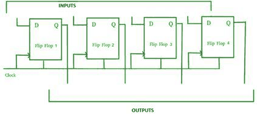
The given diagram expresses ______.
DSSSB TGT - 2023,
Answer: A
The diagram shows a parallel-in parallel-out shift register. It has four D flip-flops driven by one common clock, and each flip-flop has its own separate input line into D and its own separate output line from Q. All the bits are loaded together on a clock pulse and are available at the same time at the outputs. In a serial-in register only the first flip-flop would have an external input and the others would take their inputs from the flip-flop before, and in a serial-out register only the last output would be used, which is not what the figure shows.
Please log in or register to report this question.