Machine-translated by Google. Questions are authored in English.
Top

Multiplexers and Decoders Questions and Answers

1.

Consider the two cascaded 2-to-1 multiplexers as shown in the figure.
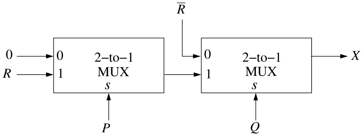
Two cascaded 2-to-1 multiplexers: the first has input 0 tied to 0, input 1 connected to R and select line P; its output feeds input 1 of the second, whose input 0 is R-bar and whose select line is Q; the output of the second MUX is X

The minimal sum of products form of the output \(X\) is

Exam Year(s)

GATE CS - 2016,

Answer: D

The output is \(X = \bar{Q}\bar{R} + PQR\).

A 2-to-1 MUX outputs input 0 when its select line is 0 and input 1 when it is 1. The first MUX outputs 0 when \(P = 0\) and \(R\) when \(P = 1\), so its output is \(PR\). The second MUX outputs \(\bar{R}\) when \(Q = 0\) and the first MUX's output \(PR\) when \(Q = 1\):

\[ X = \bar{Q}\bar{R} + Q(PR) = \bar{Q}\bar{R} + PQR \]

The two terms cannot be merged (one needs \(Q = 0\), the other \(Q = 1\)), so this is already minimal. Test values rule out the others: for \(P = 1, Q = 0, R = 0\) the circuit gives \(X = \bar{R} = 1\), but \(\bar{P}\bar{Q} + PQR\) and \(PQ + \bar{P}\bar{Q}R\) both give 0; for \(P = 0, Q = 1, R = 1\) the circuit gives 0, but \(\bar{P}Q + QR\) gives 1.

Please log in or register to report this question.
2.

Consider a digital display system (DDS) shown in the figure that displays the contents of register X. A 16-bit code word is used to load a word in X, either from S or from R. S is a 1024-word memory segment and R is a 32-word register file. Based on the value of mode bit M, T selects an input word to load in X. P and Q interface with the corresponding bits in the code word to choose the addressed word. Which one of the following represents the functionality of P, Q, and T?

(Figure: the code word has three fields, M, S-address and R-address. The S-address field feeds P, whose output goes to S; the R-address field feeds Q, whose output goes to R. The outputs of S and R are the two inputs of T, and M is connected to T. The output of T goes to X, which feeds the DDS.)

Exam Year(s)

GATE CS - 2022,

Answer: C

P is a 10:\(2^{10}\) decoder, Q is a 5:\(2^{5}\) decoder and T is a 2:1 multiplexer.

S holds 1024 = \(2^{10}\) words, so its address field has 10 bits, and P must turn those 10 bits into one select line out of 1024: that is a 10-to-\(2^{10}\) decoder. R holds 32 = \(2^{5}\) words, so Q turns 5 address bits into one of 32 select lines, a 5-to-\(2^{5}\) decoder. T has two data inputs, the word from S and the word from R, and the mode bit M chooses which one is passed to X; choosing one of two inputs under a select signal is a 2:1 multiplexer.

A 10:1 multiplexer picks one of ten inputs, which does not address 1024 words. An encoder converts one active line into a code, which is not what T does. A 1:10 de-multiplexer routes one input to ten outputs, again not an address decoder for 1024 locations.

Please log in or register to report this question.
3.

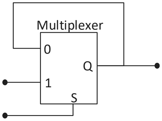
The output of a 2-input multiplexer is connected back to one of its inputs as shown in the figure.

A 2-input multiplexer whose output Q is fed back to its input 0, with input 1 and select line S as external inputs

Match the functional equivalence of this circuit to one of the following options.

Exam Year(s)

GATE CS - 2023,

Answer: B

The circuit is equivalent to a D latch.

The output Q is fed back to input 0, the external data line goes to input 1, and S selects between them:

  • S = 1: Q follows input 1, so the output tracks the data while S is high (the latch is transparent).
  • S = 0: Q takes input 0, which is Q itself, so the output holds its last value.

Following the data while an enable is high and holding it while the enable is low is a level-sensitive D latch, with S as the enable. A D flip-flop changes only on a clock edge, which needs two latches in a master-slave arrangement. A half-adder has two outputs, sum and carry, and no memory, and a demultiplexer routes one input to one of several outputs.

Please log in or register to report this question.
4.

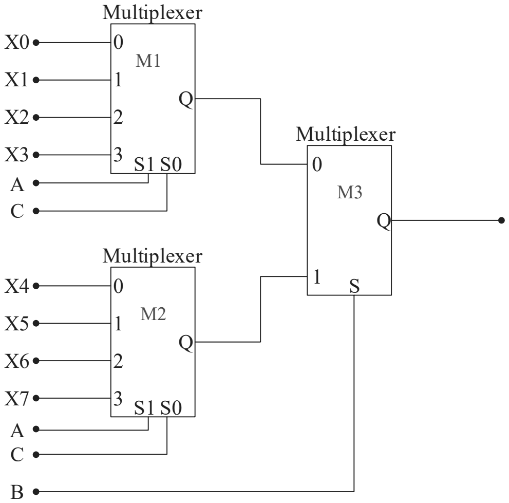
A Boolean digital circuit is composed using two 4-input multiplexers (M1 and M2) and one 2-input multiplexer (M3) as shown in the figure. X0-X7 are the inputs of the multiplexers M1 and M2 and could be connected to either 0 or 1. The select lines of the multiplexers are connected to Boolean variables A, B and C as shown.

M1 takes X0 to X3 and M2 takes X4 to X7, both with select lines S1 = A and S0 = C; their outputs feed inputs 0 and 1 of M3, whose select line is B

Which one of the following set of values of (X0, X1, X2, X3, X4, X5, X6, X7) will realise the Boolean function \(\overline{A} + \overline{A}.\overline{C} + A.\overline{B}.C\)?

Exam Year(s)

GATE CS - 2023,

Answer: C

The inputs are (1, 1, 0, 1, 1, 1, 0, 0).

First simplify the function. \(\overline{A}.\overline{C}\) is already covered by \(\overline{A}\), and \(\overline{A} + A.\overline{B}.C = \overline{A} + \overline{B}.C\):

\[ F = \overline{A} + \overline{B}C \]

M3 chooses M1 when B = 0 and M2 when B = 1. Both 4-input multiplexers select their input by (S1, S0) = (A, C).

  • B = 0: F = \(\overline{A} + C\). AC = 00, 01, 10, 11 gives X0..X3 = 1, 1, 0, 1.
  • B = 1: F = \(\overline{A}\). AC = 00, 01, 10, 11 gives X4..X7 = 1, 1, 0, 0.

The first option puts 0 in X3 and 1 in X6, the second puts 0 in X3 and 1 in X7, and the last sets X0 and X1 to 0, although F = 1 whenever A = 0.

Please log in or register to report this question.
5.

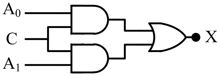
In a 2-to-1 multiplexer as shown below, the output X = A0 if C = 0, and X = A1 if C = 1.

(Figure: a block with data inputs A0 and A1, select input C and output X.)

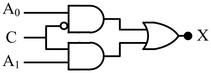
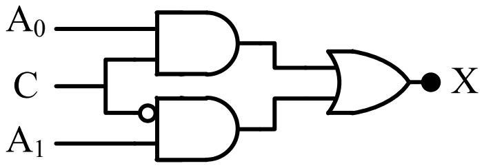
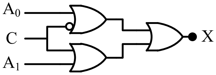
Which one of the following is the correct implementation of this multiplexer?

Exam Year(s)

GATE Physics - 2018,

Answer: A

The correct implementation is circuit (A).

A 2-to-1 multiplexer computes

\[ X = A_{0}\bar{C} + A_{1}C \]

so one AND gate must pass \(A_{0}\) when \(C = 0\), which needs \(C\) inverted at that gate, and the other must pass \(A_{1}\) when \(C = 1\), with \(C\) uninverted. An OR gate combines them. Circuit (A) has the inversion bubble on the \(C\) input of the \(A_{0}\) gate: exactly this.

Circuit (B) inverts \(C\) at the \(A_{1}\) gate, so it selects \(A_{1}\) when \(C = 0\), the reverse of the specification. Circuit (D) has no inversion, so both gates are enabled together by \(C = 1\) and both disabled by \(C = 0\). Circuit (C) uses OR gates in the first stage, which pass a 1 whenever either input is 1, so it cannot select one input.

Please log in or register to report this question.
Loading…
Tags: Multiplexers and Decoders Questions and Answers || Multiplexers and Decoders MCQ Questions and Answers || Multiplexers and Decoders GK Questions and Answers || Multiplexers and Decoders GK MCQ Questions || Multiplexers and Decoders Multiple Choice Questions and Answers || Multiplexers and Decoders GK || GK on Multiplexers and Decoders || Digital Electronics Questions and Answers || Digital Electronics MCQ Questions and Answers || Digital Electronics GK Questions and Answers || GK on Digital Electronics