
Machine-translated by Google. Questions are authored in English.
Top

Transient Analysis Questions and Answers

Direction for [ Question No: 1 To 1 ] :

Directions : The following items consist of two statements, one labelled the "Assertion" (A) and other labelled the "Reason" (R). You are to examine these two statements carefully and decide if the Assertion (A) and the Reason (R) are individually true and if so, whether the Reason is a correct explanation of the Assertion. Select your answers to these items using the codes given below and mark your answer accordingly.

1.

Assertion (A) : Logarithms are used to change a multiplication or division problem into a simpler addition and subtraction problem.

Reason (R) : The Laplace transform enables the circuit analyst to convert the set of integro differential equations describing a circuit to the complex frequency domain.

Exam Year(s)

UGC NET - 2013,

Answer: B

Both statements are true but the reason does not explain the assertion, which is option (B). Logarithms turn multiplication and division into addition and subtraction, and the Laplace transform turns the integro-differential equations of a circuit into algebraic equations in the complex frequency domain. The two are separate facts about different mathematical tools, and the Laplace transform is not the reason that logarithms simplify arithmetic. So (A) is wrong, and (C) and (D) deny a true statement.

Please log in or register to report this question.
2.

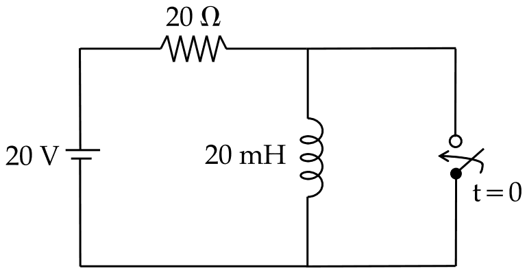
A circuit is shown in figure is in steady state, when switched on at t = 0. Assuming that the inductance is ideal, the current through inductor at t = 0+ equals :

A 20 V source in series with a 20 ohm resistor feeds a 20 mH inductor; a switch marked t = 0 is connected across the inductor

Exam Year(s)

RSMSSB JE - 2025, RSMSSB - 2025,

Answer: B

The inductor current at \(t = 0^{+}\) is 1 A.

Before the switch operates the circuit is in steady state, and an ideal inductor carrying direct current behaves as a short circuit. So the whole 20 V appears across the 20 Ω resistor:

\[ i_{L}(0^{-}) = \frac{20}{20} = 1\ \text{A} \]

The current through an inductor cannot change instantaneously, because that would need infinite voltage, so \(i_{L}(0^{+}) = i_{L}(0^{-}) = 1\) A. Closing the switch across the inductor only lets that current circulate through the switch, where it stays in the ideal case.

0 A ignores the continuity of inductor current, and 0.5 A or 2 A do not follow from the circuit values.

Please log in or register to report this question.
3.

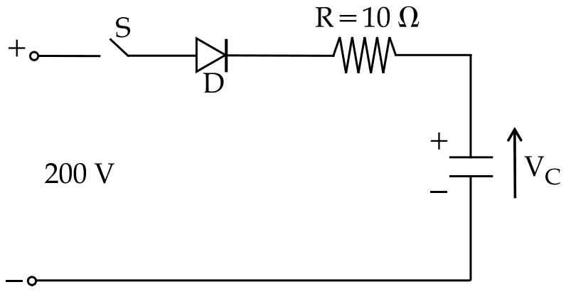
In figure given below, capacitor 'C' is charged to V0 = 100 V with upper plate positive. At time t = 0, switch S is closed. Current through the circuit at t = 0 and final voltage across 'C' are __________.

A 200 V source in series with switch S, diode D and R = 10 ohm charging a capacitor whose upper plate is plus and whose voltage is VC

Exam Year(s)

RSMSSB JE - 2025, RSMSSB - 2025,

Answer: B

The current at \(t = 0\) is 10 A and the final capacitor voltage is 200 V.

At the instant the switch closes, the capacitor already holds 100 V opposing the 200 V source, and the diode is forward biased because the source is the higher. The net voltage drives the current through R:

\[ i(0) = \frac{200 - 100}{10} = 10\ \text{A} \]

The capacitor then charges until its voltage equals the source voltage, 200 V, at which point the current falls to zero; the diode stops it from reversing. 20 A ignores the initial charge on the capacitor, and 150 V is only the average of the two voltages, not where the charging stops.

Please log in or register to report this question.
4.

Time constant for an R-L series circuit is given by :

Exam Year(s)

RSMSSB JE - 2025, RSMSSB - 2025,

Answer: A

The time constant is \(\tau = \frac{L}{R}\).

When a dc voltage is switched onto an R-L series circuit, the current rises as \(i = I\left(1 - e^{-Rt/L}\right)\). The time constant is the time in which the current would reach its final value if it kept its initial rate of rise; in practice it is the time to reach 63.2 per cent of the final value. Henry divided by ohm gives seconds.

R/L is the reciprocal, with units of 1/second. RL has units of ohm-henry, not time, and 1/RL is no better. The R-C circuit's time constant is RC, which may be the source of the RL trap.

Please log in or register to report this question.

5.

The Laplace transform of first derivative of function f(t) is :

Exam Year(s)

MH SET - 2019, SET Exam - 2019,

Answer: B

The Laplace transform of the first derivative is \(sF(s) - f(0)\).

Integrating by parts:

\[ \begin{aligned} \mathcal{L}\{f'(t)\} &= \int_{0}^{\infty} f'(t) e^{-st} dt \\ &= \left[f e^{-st}\right]_{0}^{\infty} + s\int_{0}^{\infty} f e^{-st} dt \\ &= sF(s) - f(0) \end{aligned} \]

The initial value f(0) is what lets the Laplace method solve differential equations with initial conditions. F(s)/s is the transform of the integral of f(t), not its derivative, and F(s) − f(0) and f(0) alone are missing the factor s.

Please log in or register to report this question.

6.

State variable analysis is not applicable to which of the following circuits ?

Exam Year(s)

MH SET - 2019, SET Exam - 2019,

Answer: A

State variable analysis is not applicable to a circuit consisting of resistors only.

State variables describe the energy stored in a circuit: capacitor voltages and inductor currents. The state equations are first-order differential equations for these variables, and their number equals the number of independent energy-storage elements.

A purely resistive circuit stores no energy and has no memory: its voltages and currents are fixed instantly by the sources through algebraic equations, so there are no state variables and nothing for state variable analysis to describe. RC, LC and RLC circuits all contain storage elements and are natural candidates for it.

Please log in or register to report this question.

7.

A DC voltage source is connected across a series RLC circuit. Under steady state conditions, the applied DC voltage drops entirely across the :

Exam Year(s)

MH SET - 2020, SET Exam - 2020,

Answer: A

In the steady state the whole DC voltage appears across C only.

Once the transients have died out, the capacitor is fully charged and behaves as an open circuit to DC, so no current flows in the series loop.

With zero current there is no voltage across the resistor (V = IR = 0), and none across the inductor, which is a short circuit to steady DC (V = L di/dt = 0). By Kirchhoff's voltage law the entire source voltage must then appear across the capacitor. That rules out R only, L only and the R-L combination.

Please log in or register to report this question.

8.

Consider a DC voltage source VS connected to a series RC circuit. When the steady state reaches, the ratio of the energy stored in the capacitor to the total energy supplied by the voltage source is equal to :

Exam Year(s)

MH SET - 2020, SET Exam - 2020,

Answer: C

The ratio is 0.500.

Charging the capacitor to \(V_{S}\) moves a total charge \(Q = CV_{S}\) through the source, so the source supplies energy \(QV_{S} = CV_{S}^{2}\). The capacitor ends up storing only \(\frac{1}{2}CV_{S}^{2}\).

\[ \frac{\frac{1}{2}CV_{S}^{2}}{CV_{S}^{2}} = 0.5 \]

The other half is dissipated as heat in the resistor, whatever its value. 0.632 is the fraction of the final voltage reached after one time constant \((1 - e^{-1})\), a different quantity; 1.000 would mean a lossless charge, which a series resistor rules out.

Please log in or register to report this question.

Answer: A

The correct matrix form is the first one, with \(di_{L}/dt\) and \(dV_{c}/dt\) on the left and the matrix with rows (-R/L, -1/L) and (1/C, 0).

Take the inductor current and the capacitor voltage as the state variables. Rearranging the loop equation gives the first state equation, and the capacitor law \(i_{L} = C\, dV_{c}/dt\) gives the second:

\[ \begin{aligned} \frac{di_{L}}{dt} &= -\frac{R}{L} i_{L} - \frac{1}{L} V_{c} \\ \frac{dV_{c}}{dt} &= \frac{1}{C} i_{L} \end{aligned} \]

The second option swaps the order of the derivatives without swapping the matrix rows. The third puts the derivatives on the wrong side, and the fourth swaps the two rows, so each pairs the coefficients with the wrong state.

Please log in or register to report this question.

10.

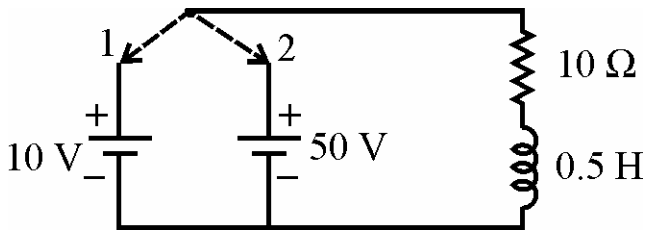
The switch is in position 1 for long time. It is changed to position 2 at t = 0. The initial condition for current is \(i(0_{-})\) =

A switch can connect a 10 V battery (position 1) or a 50 V battery (position 2) in series with a 10 ohm resistor and a 0.5 henry inductor.

Exam Year(s)

UGC NET - 2012,

Answer: B

The initial current is 1 A, option (B). With the switch in position 1 for a long time, the 10 V battery has been connected to the 10 ohm resistor and 0.5 H inductor for many time constants, so the circuit is in steady state. In d.c. steady state the inductor acts as a short circuit and the current is set by the resistor alone.

\[ i(0^{-}) = \frac{10\ \text{V}}{10\ \Omega} = 1\ \text{A} \]

Because the current in an inductor cannot change at once, this value also holds just after the switch moves to position 2. Option (C), 5 A, would be the final current with the 50 V battery. Option (A), 0 A, and option (D), 25 A, do not follow from either battery.

Please log in or register to report this question.

Loading…
Tags: Transient Analysis Questions and Answers || Transient Analysis MCQ Questions and Answers || Transient Analysis GK Questions and Answers || Transient Analysis GK MCQ Questions || Transient Analysis Multiple Choice Questions and Answers || Transient Analysis GK || GK on Transient Analysis || Network Analysis Questions and Answers || Network Analysis MCQ Questions and Answers || Network Analysis GK Questions and Answers || GK on Network Analysis