Machine-translated by Google. Questions are authored in English.
Top

Shear Force and Bending Moment Diagrams Questions and Answers

1.

A beam, of 5 m effective span, has its left end 'P' as a free end; whereas its right end 'Q' is a fixed supported end. The beam is subjected to a uniformly distributed load of 3 kN/m on the entire span. Find the point with the maximum shear force.

Exam Year(s)

DSSSB JE - 2023,

Answer: A

The beam is a cantilever, free at P and fixed at Q, and loaded with a UDL of 3 kN/m. The shear force at a section a distance x from the free end is \(w x\), which grows steadily towards the fixed end and is greatest at the fixed support:

\[ V_{max} = wL = 3 \times 5 = 15\ \text{kN at Q} \]

The shear at the free end P is zero, and at the midpoint it is 7.5 kN and at 1 m from the fixed support it is 12 kN, both smaller than the 15 kN at Q.

Please log in or register to report this question.

2.

A continuous beam ABC is subjected to loads and its shear force and bending moment diagrams are given below. What is the fixing moment at support B?

A continuous beam ABC with a 3 kN point load at D, 2 m from A, supports at A, B and C 4 m apart, and a 1 kN/m load on BC. Below it are the bending moment diagram, with 4 at D, 2.4 (negative) at B and 2 at the middle of BC, and the shear force diagram, with 1.6, 1.4, 2.6 and 1.4.

Exam Year(s)

DSSSB JE - 2023,

Answer: C

The bending moment diagram shows the moment at the intermediate support B as 2.4 kN-m with a negative sign, since the moment there is hogging (the shaded region over B is marked negative). The fixing moment at the support is therefore -2.4 kN-m. The positive moments in the figure, 4 kN-m under the 3 kN load and 2 kN-m near the middle of BC, are sagging moments in the spans and are not the moment at the support. The options 1.4 and 1.8 kN-m have no basis in the figure (1.4 is a shear force value), and -2.8 kN-m is not shown.

Please log in or register to report this question.
3.

For a cantilever beam subjected to a uniformly distributed load (UDL) along its length, the shape of the bending moment diagram is:

Exam Year(s)

DSSSB - 2023,

Answer: C

For a cantilever carrying a uniformly distributed load over its whole length the bending moment diagram is parabolic. At a distance x from the free end the bending moment is \[ M = -\frac{wx^{2}}{2} \] which is a quadratic function of x, so the diagram is a parabola. A point load would give a linear diagram, and an elliptical shape does not arise from this loading.

Please log in or register to report this question.
4.

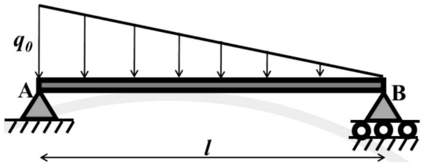
A simply supported horizontal beam is subjected to a distributed transverse load varying linearly from \(q_{0}\) at A to zero at B, as shown in the figure. Which one of the following options is correct?

Beam AB of length l on a pin support at A and a roller support at B, carrying a downward distributed load that falls linearly from q0 at A to zero at B

Exam Year(s)

GATE AE - 2025,

Answer: A

The reaction at A is larger than that at B.

The triangular load has total magnitude \(\frac{1}{2}q_{0}l\), acting at its centroid, \(l/3\) from A, the heavy end. Taking moments about A and then summing vertical forces:

\[ \begin{aligned} R_{B}\,l &= \tfrac{1}{2}q_{0}l \cdot \tfrac{l}{3} \Rightarrow R_{B} = \tfrac{1}{6}q_{0}l \\ R_{A} &= \tfrac{1}{2}q_{0}l - \tfrac{1}{6}q_{0}l = \tfrac{1}{3}q_{0}l \end{aligned} \]

So \(R_{A} = 2R_{B}\). The reactions would be equal only for a load symmetric about mid-span. A simply supported beam has two unknown vertical reactions and two equilibrium equations, so the reactions are statically determinate.

Please log in or register to report this question.

5.

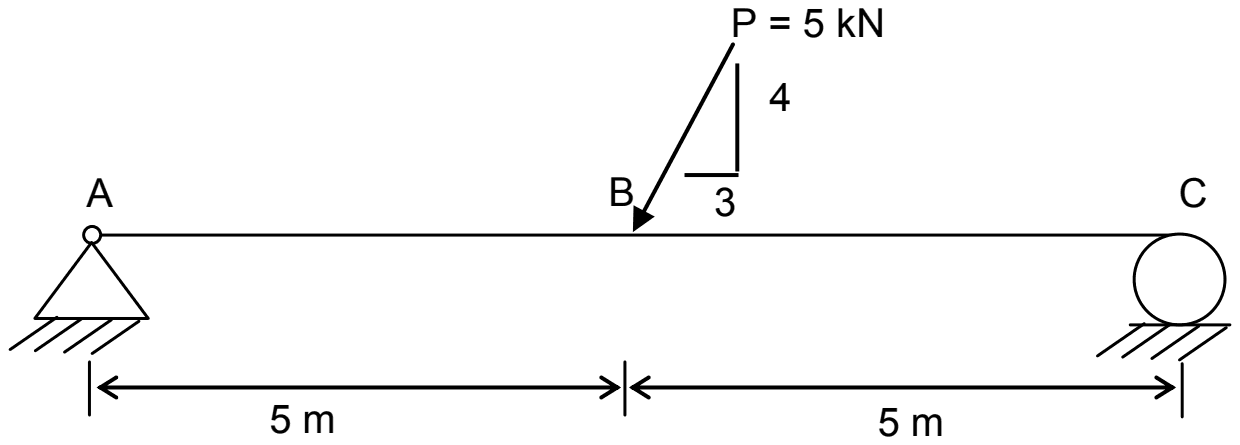
The axial force diagram for the weightless beam subjected to the inclined force P = 5 kN is

Beam AC of two 5 m spans, pinned at A and on a roller at C, with P = 5 kN acting down at B, sloped 4 vertical to 3 horizontal towards A

Exam Year(s)

GATE XE - 2012,

Answer: A

The correct axial force diagram is (A): 3 kN in AB and zero in BC.

The 5 kN force has a 3:4:5 slope, so its components are 4 kN vertical and 3 kN horizontal, the horizontal part pointing towards A. The roller at C gives only a vertical reaction, so the whole horizontal component must be taken by the pin at A.

A section in AB therefore carries 3 kN of axial force (the force at B pushes towards A, which pushes back), while a section in BC has no horizontal force on either side and carries zero. Diagram (B) wrongly spreads the force over the whole beam, (C) splits it between the supports as if both resisted horizontally, and (D) puts it in the wrong span.

Please log in or register to report this question.

6.

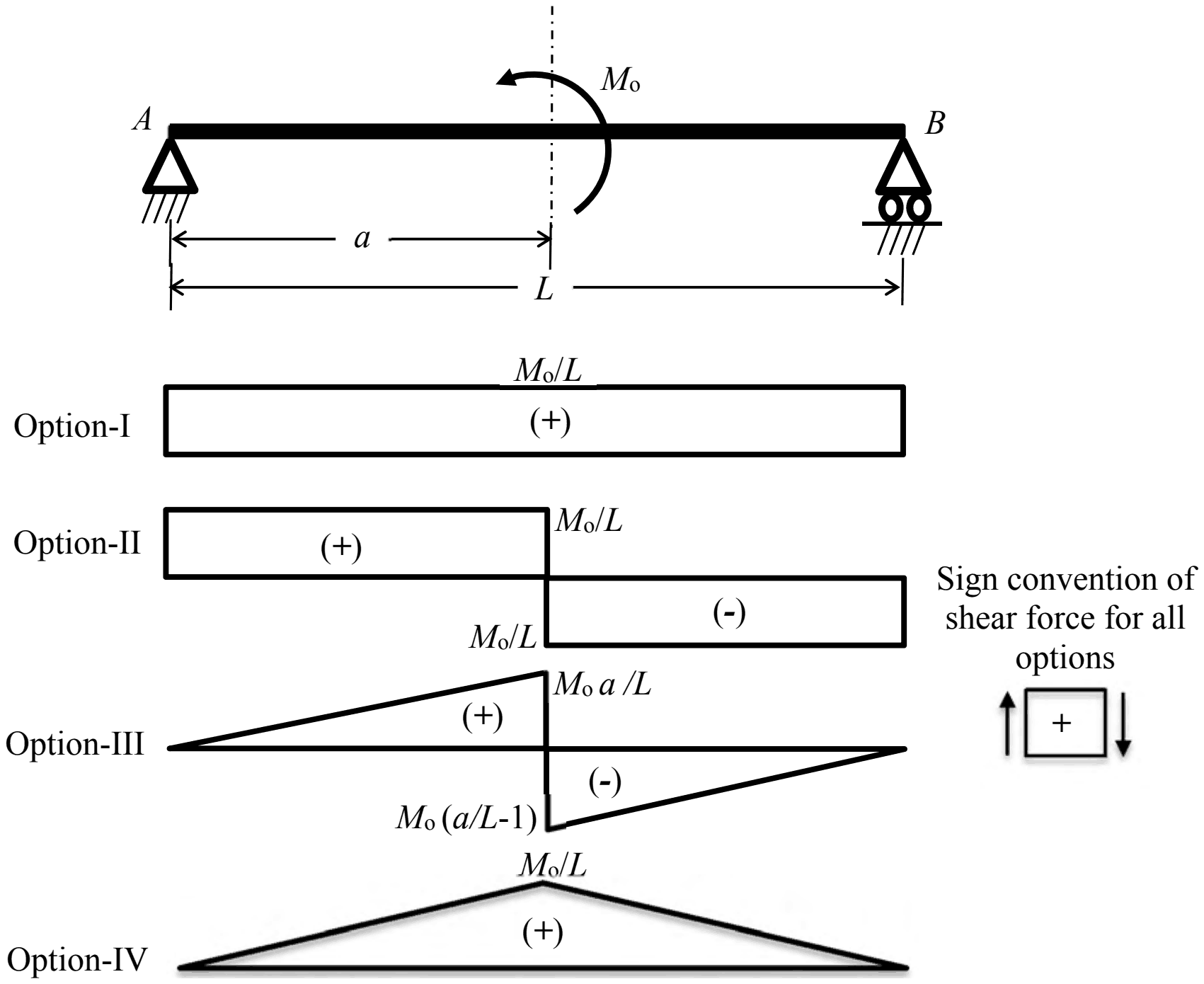
A simply supported beam of span L is subjected to a couple Mo at a distance a from support A. Among the four options (Option-I to Option-IV) shown, the correct shear force diagram of the beam is

Beam AB with a counter-clockwise couple Mo at distance a from A, and four shear force diagrams: I a constant Mo/L (+); II +Mo/L before the couple and -Mo/L after; III triangles reaching Mo a/L and Mo(a/L-1); IV a triangle peaking at Mo/L

Exam Year(s)

GATE XE - 2018,

Answer: A

The shear force diagram is Option-I, a constant \(M_{o}/L\) of positive sign.

A couple has no net vertical force, so the support reactions form an equal and opposite pair. Taking moments about B for the counter-clockwise couple gives \(R_{A} = M_{o}/L\) upward and \(R_{B} = M_{o}/L\) downward. These are the only vertical forces, and a concentrated couple changes the bending moment, not the shear force, so the shear is \(M_{o}/L\) along the whole span. With the sign convention shown (upward force on the left face positive) it is positive.

Option II shows a jump in shear at the couple, which only a concentrated force can cause. Options III and IV show sloping shear, which needs a distributed load, and none acts on the beam. The jump at the couple belongs in the bending moment diagram instead.

Please log in or register to report this question.
7.

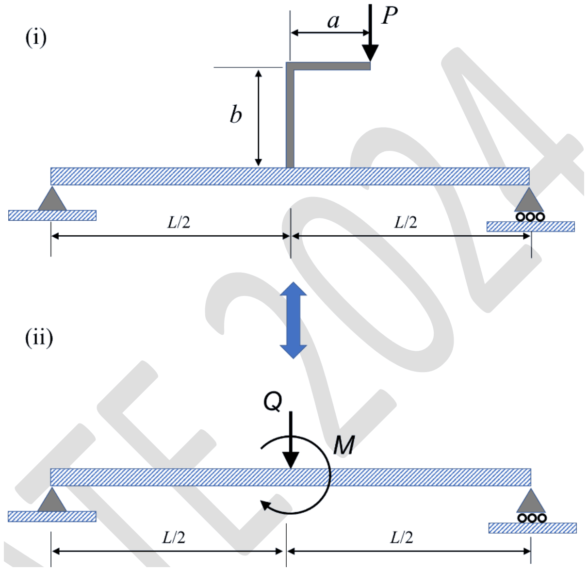
An L-shaped rigid member is fixed at the midpoint of a simply-supported beam, as shown in figure (i). The member is subjected to a vertically downward force \(P\) at its free end. In an equivalent system, the member along with the applied load is replaced with a force \(Q = P\) and a moment \(M\) (see figure (ii)). Which of the following statements is correct?

(Neglect the mass of the beam and of the rigid member)

(i) Simply supported beam of span L with an L-shaped arm at mid-span rising height b and extending horizontally a, loaded by a downward force P at its tip; (ii) the same beam with a downward force Q and a moment M at mid-span

Exam Year(s)

GATE XE - 2024,

Answer: A

The equivalent moment is \(M = Pa\).

Moving a force to a new point without changing its effect requires adding a couple equal to the force times the perpendicular distance between the old and new lines of action. P is vertical and acts at a horizontal distance a from the vertical leg, which is fixed at mid-span, so moving it to the beam gives Q = P plus

\[ M = P \times a \]

The height b does not count, because it is measured along the line of action of the vertical force and contributes no moment arm. That rules out Pb and P(a + b), and M = 0 would hold only if P acted directly above the attachment point.

Please log in or register to report this question.

8.

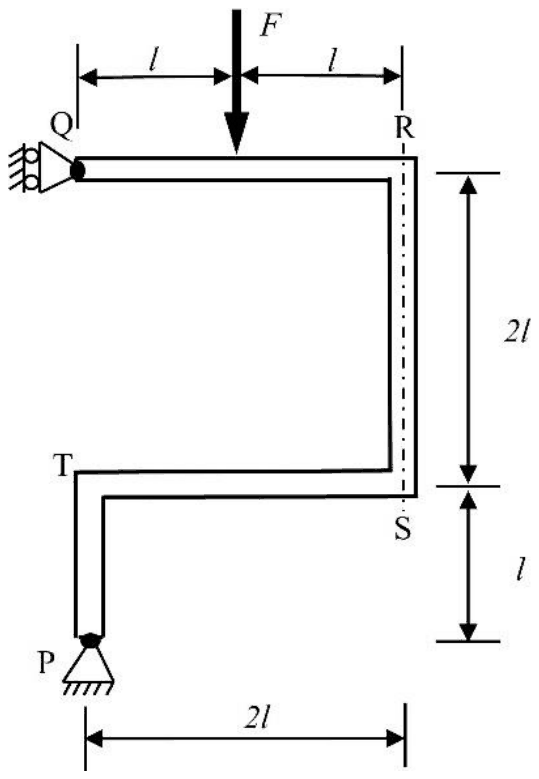
Which one of the following options is the CORRECT absolute value of the bending moment at R in the frame as shown in the figure?

A frame Q-R-S-T-P: horizontal member QR of length 2l with a downward load F at its midpoint, vertical member RS of length 2l, horizontal ST of length 2l back to the left, and vertical TP of length l down to a pin support at P; Q rests on a roller against a vertical wall

Figure is not to scale

Exam Year(s)

GATE XE - 2026,

Answer: B

The bending moment at R is Fl.

The roller at Q gives only a horizontal reaction H, along the member QR. Cut the frame just at R and take moments of the forces on the part Q-R about R:

  • H acts along the line of QR, so it has no moment about R.
  • The load F acts at the midpoint of QR, a distance l from R, giving a moment Fl.

So \(|M_{R}| = Fl\). (For completeness, moments about P give H = F/3, but its value does not affect the moment at R.)

Zero would need F to act at R, and 2Fl or 3Fl take lever arms of 2l or 3l, the length of QR or the frame's height, instead of the distance from F to R.

Please log in or register to report this question.
Loading…
Tags: Shear Force and Bending Moment Diagrams Questions and Answers || Shear Force and Bending Moment Diagrams MCQ Questions and Answers || Shear Force and Bending Moment Diagrams GK Questions and Answers || Shear Force and Bending Moment Diagrams GK MCQ Questions || Shear Force and Bending Moment Diagrams Multiple Choice Questions and Answers || Shear Force and Bending Moment Diagrams GK || GK on Shear Force and Bending Moment Diagrams || Strength of Materials Questions and Answers || Strength of Materials MCQ Questions and Answers || Strength of Materials GK Questions and Answers || GK on Strength of Materials