
Machine-translated by Google. Questions are authored in English.
Top

Diode Circuits and Applications Questions and Answers

101.

Consider the following pairs of quantity and the rectifier property it describes.

Ripple factor - Alternating content relative to direct

Form factor - Root-mean-square relative to average

Peak inverse voltage - Reverse stress on the diode

Rectification efficiency - Heat dissipated in the diode

How many of the pairs given above are correctly matched?

Answer: B

The first three are correctly paired and the fourth is not, so three match. Rectification efficiency measures the fraction of input power appearing as direct output; the remainder is largely in the ripple rather than dissipated as heat. Each figure of merit isolates one aspect of the same waveform, and knowing what each is a ratio of is what makes them comparable across topologies.

Please log in or register to report this question.
Answer: C

A few picofarads is a low impedance at hundreds of megahertz, so signal leaks straight through a diode that is supposed to be blocking, which is why switching diodes for radio work are specified for low capacitance. The forward drop, the thermal behaviour and the leakage are all unaffected by it. A parasitic that is negligible at one frequency and dominant at another is the normal situation, and the only question is where the crossover lies.

Please log in or register to report this question.

Answer: D

A PIN diode's thick intrinsic layer makes it behave as a current-controlled resistor at radio frequencies, so a bias current switches or attenuates a signal without the distortion an ordinary diode would cause. References, tuning and light emission belong to the Zener, the varactor and the light emitting diode respectively. Adding an undoped layer to change a device's high-frequency behaviour completely is a good illustration of how much structure matters alongside material.

Please log in or register to report this question.

Answer: A

The rating that actually destroys the device is junction temperature, and thermal resistance is what converts dissipated power into the rise above ambient. The forward drop and leakage are measured at stated temperatures but are not what the figure is for, and the surge rating is a separate specification. Any thermal calculation works backwards from the limiting temperature through the resistances to the power that may be allowed, which is why the path is specified end to end.

Please log in or register to report this question.

105.

A diode dissipates \( 1 \ \mathrm{W} \) with a thermal resistance of \( 60 \ \mathrm{^\circ C/W} \) in a \( 40 \ \mathrm{^\circ C} \) ambient. Its junction reaches

Answer: B

Adding the rise to the ambient:

\[ T_{j} = 40 + (1 \times 60) = 100 \ \mathrm{^\circ C} \]

giving 100 degrees, safely below a silicon limit of 150 but leaving little margin for a hotter ambient. Sixty degrees is the rise alone and forty the ambient alone. Whether a device survives is decided by the sum rather than either term, which is why an ambient specification is as much part of a rating as the power figure.

Please log in or register to report this question.

106.

With a heatsink halving that thermal resistance, the same dissipation gives a junction temperature of

Answer: C

Halving the resistance halves the rise:

\[ T_{j} = 40 + (1 \times 30) = 70 \ \mathrm{^\circ C} \]

so 70 degrees, a thirty degree improvement bought entirely with metal. Fifty degrees would need a quarter of the original resistance. Because the rise is proportional to the resistance, halving one halves the other exactly, which makes heatsink sizing one of the more straightforward calculations in a power design.

Please log in or register to report this question.

Answer: D

Reverse saturation current roughly doubles for every ten degrees, so a device that leaks microamps at room temperature can leak milliamps when hot - and since that leakage dissipates power under reverse voltage, it can feed a thermal runaway. It does not reverse direction, remains largely independent of reverse voltage, and stays far below the forward current. Any mechanism whose effect grows with the temperature it produces has to be checked for runaway rather than merely tabulated.

Please log in or register to report this question.

Answer: A

Because sixty millivolts changes the current tenfold, setting a diode's current by applying a voltage is hopelessly imprecise, and the current must be set by a series element. The forward drop is easy to measure at a known current, leakage is measurable with care, and frequency is a separate matter. Every device with an exponential characteristic is driven from a current rather than a voltage for exactly this reason, which is why the same arrangement appears with light emitting diodes and transistor base junctions.

Please log in or register to report this question.

Answer: B

Differentiating the diode equation gives a slope resistance of the thermal voltage divided by the current, so at one milliamp it is about 26 ohms and at ten it is about 2.6. Bulk resistance, capacitance and stored charge are all real effects but none produces this relation. A current-controlled resistance falling as one over the current is what makes diodes and transistor junctions useful as variable elements, and the same expression reappears throughout small-signal analysis.

Please log in or register to report this question.

Answer: C

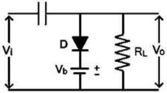
The circuit has a series capacitor, a shunt diode with a battery and the load across the output, which is the form of a clamper (a dc restorer) that shifts the level of the whole waveform without changing its shape.


In the figure the diode is placed so that it conducts when the output tries to go above the battery voltage. Once the capacitor charges during the first conducting interval, it holds the output peaks at the bias level, so the waveform is shifted down: this is a negative clamper. The battery is connected so that its positive terminal is on the diode side, so the clamping level is a positive voltage, and the circuit is a negative clamper with positive bias, option C.


A positive clamper would have the diode reversed so that the output bottoms out near the bias level instead.

Please log in or register to report this question.

Loading…

Other Subjects

Tags: Diode Circuits and Applications Questions and Answers || Diode Circuits and Applications MCQ Questions and Answers || Diode Circuits and Applications GK Questions and Answers || Diode Circuits and Applications GK MCQ Questions || Diode Circuits and Applications Multiple Choice Questions and Answers || Diode Circuits and Applications GK || GK on Diode Circuits and Applications || Analog Electronics Questions and Answers || Analog Electronics MCQ Questions and Answers || Analog Electronics GK Questions and Answers || GK on Analog Electronics