Machine-translated by Google. Questions are authored in English.
Top

Diode Circuits and Applications Questions and Answers

111.

For the given clamper circuit, the diode is ideal.
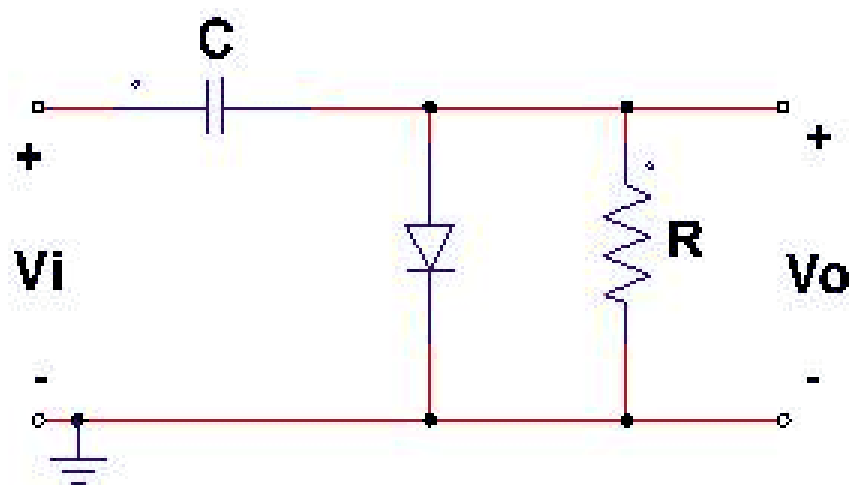
Clamper circuit: input Vi through a series capacitor C, a diode D across the output to the ground line, and a resistor R across the output Vo

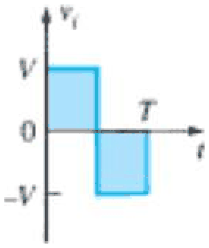
The input Vi is:

Input waveform Vi: a square wave that is +V for the first half period and -V for the second half period of T

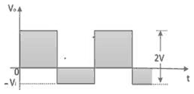
The output Vo is:

Exam Year(s)

DSSSB AE - 2023,

Answer: C

The capacitor in series charges through the diode, and the clamper shifts the dc level of the input without changing its shape. The diode is connected with its anode at the output node, so it conducts when the output tries to go positive. During the first half cycle (input \(+V\)) the diode conducts and the capacitor charges to \(V\), keeping the output at about 0 V. When the input falls to \(-V\) the diode is off and the output is the input minus the capacitor voltage, \(-V - V = -2V\).


So the output is a square wave between 0 and \(-2V\), which is figure (C). Figure (A) and (B) swing positive, so they would need the diode reversed, and figure (D) is the input itself without a shift. The answer is option C.

Please log in or register to report this question.
112.

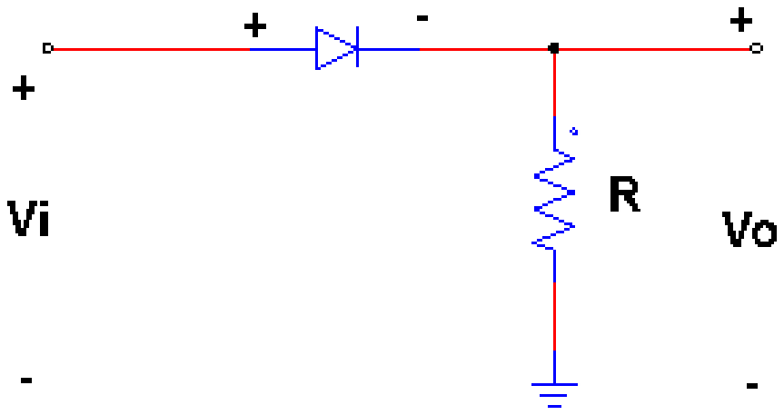
For the given circuit, the diode is ideal.

Half-wave rectifier circuit: input Vi through a series diode, with a resistor R across the output Vo

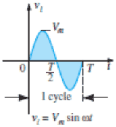
The input to this circuit is:

Input waveform Vi equals Vm sin(omega t), shown for one cycle from 0 to T with T/2 marked

The output voltage \(V_o\) from \(T/2\) to \(T\) will be:

Exam Year(s)

DSSSB AE - 2023,

Answer: A

The circuit is a half wave rectifier: the ideal diode is in series with the load resistor. The diode conducts when the anode is positive with respect to the cathode, that is during the positive half cycle (0 to \(T/2\)), when the output follows the input.


From \(T/2\) to \(T\) the input is negative, so the diode is reverse biased and acts as an open circuit. No current flows through \(R\), and so the output voltage \(V_o = iR = 0\). The output is zero, option A. The values \(V_m\) and \(V_m/2\) would be the output during the positive half, and \(-V_m\) would appear only if the diode were short circuited, but then it would appear across the diode, not the load.

Please log in or register to report this question.
113.

In the given circuit, the diodes are ideal.

Bridge rectifier circuit: input Vi across the bridge of four diodes D1 to D4, with a resistor R carrying the output voltage Vo across the bridge

The input to this circuit is:

Input waveform: one full sine cycle of amplitude Vm from 0 to pi, with pi/2 marked

where \(V_m\) is 250 V. The value of DC output voltage is:

Exam Year(s)

DSSSB AE - 2023,

Answer: D

The circuit is a full wave bridge rectifier with ideal diodes. Both half cycles of the input appear at the load with the same polarity, so the average (dc) output voltage is


\[ \begin{aligned} V_{dc} = \frac{2V_m}{\pi} \\ &= \frac{2 \times 250}{\pi} = 159.2\ \text{V} \end{aligned} \]


The value for a half wave rectifier would be \(V_m/\pi = 79.6\) V. The options 0.159, 1.59 and 15.9 V are 1000, 100 and 10 times too small, which would come from \(V_m\) taken as 0.25, 2.5 or 25 V. The answer is 159 V, option D.

Please log in or register to report this question.

114.

Choose the most appropriate matching of the items in Column 1 with those in Column 2.

Column 1Column 2
(i) PIN diodeP. Voltage regulation
(ii) Tunnel diodeQ. Radio frequency and microwave devices
(iii) Zener diodeR. Optoelectronic detection
(iv) Photo diodeS. Oscillator

Exam Year(s)

GATE Physics - 2023,

Answer: A

The correct matching is (i) - Q; (ii) - S; (iii) - P; (iv) - R.

  • The PIN diode, with its wide intrinsic layer and low capacitance, is used as a switch and attenuator in radio-frequency and microwave devices (Q).
  • The tunnel diode has a region of negative differential resistance, which lets it sustain oscillations (S).
  • The Zener diode holds a nearly constant voltage in reverse breakdown, the basis of voltage regulation (P).
  • The photo diode turns incident light into current, for optoelectronic detection (R).

The other options give the Zener diode a role other than regulation, or the tunnel diode a role other than oscillation, so they fail on at least one pair.

Please log in or register to report this question.

115.

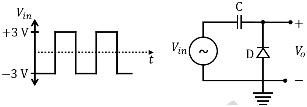
The symbols C, D, \(V_{in}\) and \(V_{0}\) shown in the figure denote capacitor, ideal diode, input voltage and output voltage, respectively.

Input: a square wave between +3 V and -3 V. Circuit: Vin in series with capacitor C to the output terminal; diode D from ground to the output, its anode at ground and cathode at the output

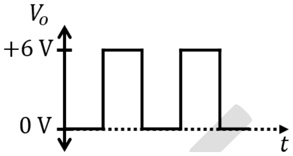
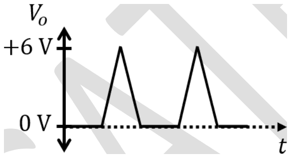
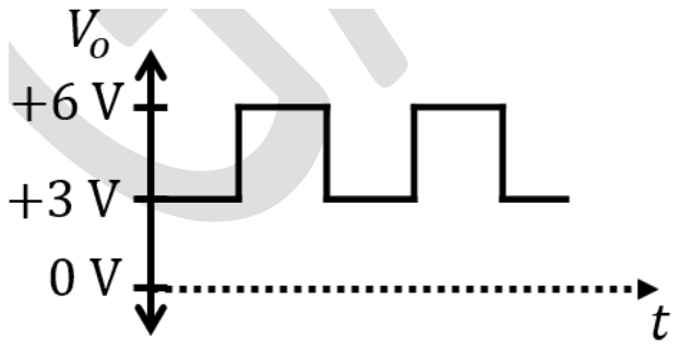
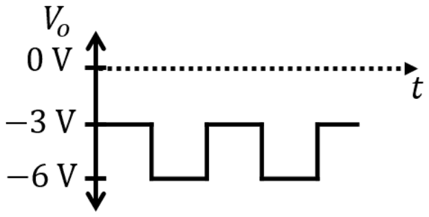
Which one of the following output waveforms \((V_{0})\) is correct for the given input waveform \((V_{in})\)?

Exam Year(s)

GATE Physics - 2024,

Answer: A

The output is a square wave between 0 V and +6 V (A).

This is a positive clamper. The diode runs from ground (anode) to the output (cathode), so it conducts whenever the output tries to go below 0 V. During the -3 V half of the input the diode conducts and the capacitor charges to 3 V, with its output side 3 V above its input side. Afterwards the diode stays off and the capacitor simply adds 3 V to the input:

\[ \begin{aligned} V_{0} &= V_{in} + 3\ \text{V} \\ -3\ \text{V} &\to 0\ \text{V}, \quad +3\ \text{V} \to +6\ \text{V} \end{aligned} \]

The shape of the input is preserved, so triangular pulses (B) are wrong. A wave between +3 V and +6 V (C) has the wrong shift and amplitude, and a wave between -3 V and -6 V (D) is what a clamper with the diode reversed would give, and with a halved swing.

Please log in or register to report this question.
116.

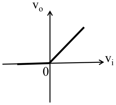
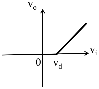
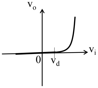
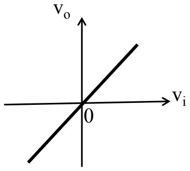
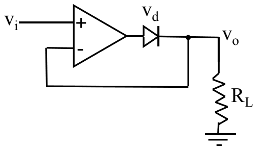
Which one of the following graphs shows the correct variation of vo with vi? Here, vd is the voltage drop across the diode and the Op-Amp is assumed to be ideal.

Op-amp with input vi at the non-inverting input; its output drives a diode whose cathode is the output vo across load RL to ground, and vo is fed back to the inverting input

Exam Year(s)

IIT JAM - 2018,

Answer: A

The correct graph is (A): \(v_{o} = 0\) for negative \(v_{i}\) and \(v_{o} = v_{i}\) for positive \(v_{i}\).

The circuit is a precision (super) diode. For \(v_{i} \gt 0\) the op-amp output rises until the diode conducts; the feedback taken from \(v_{o}\) then forces \(v_{o} = v_{i}\), and the op-amp output simply sits \(v_{d}\) higher to cover the diode drop. For \(v_{i} \lt 0\) the op-amp output swings negative, the diode is reverse biased, and \(R_{L}\) pulls \(v_{o}\) to 0.

Graph (B), with a threshold at \(v_{d}\), and graph (C), with the exponential diode curve, describe an ordinary diode without the op-amp; the feedback removes the diode drop entirely. Graph (D) is a plain follower with no rectification.

Please log in or register to report this question.
117.

The power efficiency of a centre-tapped secondary full wave rectifier is: (Choose the most appropriate option from below)

Exam Year(s)

RSMSSB JE - 2025, RSMSSB - 2025,

Answer: D

The keyed efficiency is 81%.

The rectification efficiency of a full wave rectifier, whether centre-tapped or bridge, is the dc output power divided by the ac input power. For an ideal rectifier it is 8/π2, which is 0.812, or 81.2%, twice the 40.6% of a half wave rectifier.

48% is the ripple factor of a full wave rectifier (0.482), which is easily confused with efficiency, and 57% and 77% do not correspond to a standard rectifier figure.

Please log in or register to report this question.
118.

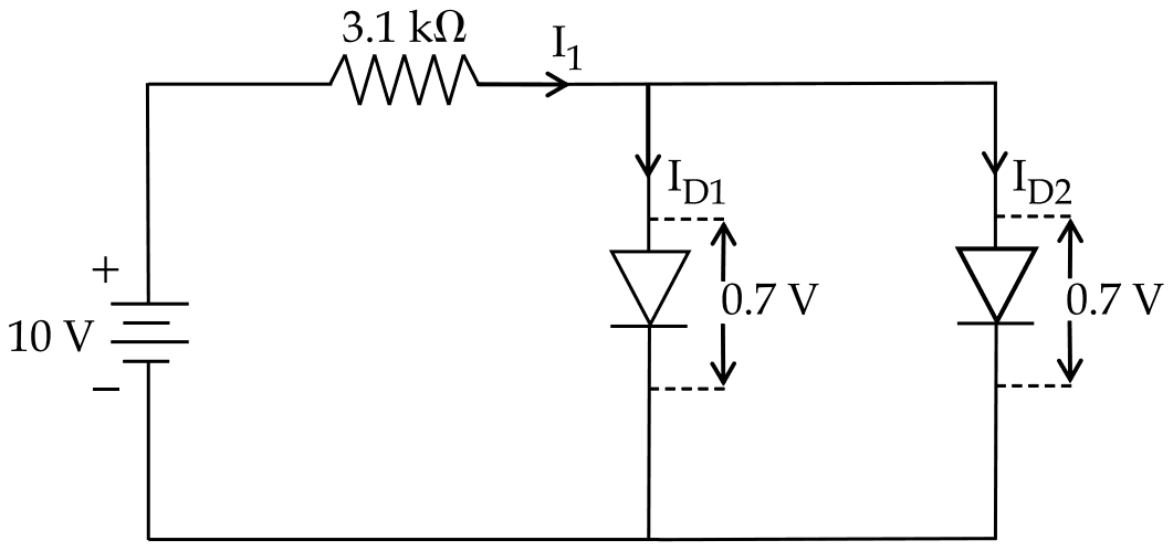
The parallel combination of two diodes are connected in series with battery and resistance as shown in figure. The diodes are identical and have forward breakdown voltage of 0.7 V. The diode currents are __________.

A 10 V battery in series with a 3.1 kilohm resistor carrying I1 into two parallel forward-biased diodes carrying ID1 and ID2, each with 0.7 V across it

Exam Year(s)

RSMSSB JE - 2025, RSMSSB - 2025,

Answer: C

The diode currents are 1.5 mA and 1.5 mA.

The parallel diodes hold 0.7 V across themselves, so the resistor carries the rest of the battery voltage, and the identical diodes share the current equally.

\[ \begin{aligned} I_{1} &= \frac{10 - 0.7}{3.1\ \text{k}\Omega} = 3\ \text{mA} \\ I_{D1} &= I_{D2} = \frac{3}{2} = 1.5\ \text{mA} \end{aligned} \]

3 mA each forgets that the total divides between the two diodes. 3.22 or 3.23 come from ignoring the 0.7 V drop (\(10/3.1 \approx 3.23\) mA), and amperes instead of milliamperes is a units slip.

Please log in or register to report this question.
119.

The current through Zener diode in the following circuit is :

An 18 V source feeds a 270 ohm series resistor; a 10 V Zener diode in reverse bias and a 1 kilohm load are connected in parallel after it

Exam Year(s)

RSMSSB JE - 2025, RSMSSB - 2025,

Answer: C

The Zener current is about 19.6 mA.

Without the Zener the load would see \(18 \times \frac{1000}{1270} \approx 14.2\) V, more than 10 V, so the Zener breaks down and holds the load at 10 V. Then:

\[ \begin{aligned} I_{S} &= \frac{18 - 10}{270} \approx 29.6\ \text{mA} \\ I_{L} &= \frac{10}{1000} = 10\ \text{mA} \\ I_{Z} &= 29.6 - 10 = 19.6\ \text{mA} \end{aligned} \]

29.6 mA is the current in the series resistor, which forgets that 10 mA of it goes to the load. 14.8 mA and 39.6 mA do not follow from the circuit.

Please log in or register to report this question.
120.

Junction breakdown of a PN junction diode occurs :

Exam Year(s)

RSMSSB JE - 2025, RSMSSB - 2025,

Answer: C

Junction breakdown occurs with reverse bias.

A reverse-biased PN junction passes only a tiny leakage current until the reverse voltage reaches the breakdown voltage. The current then rises sharply, either by avalanche multiplication (in lightly doped junctions, where carriers gain enough energy to knock out more carriers) or by zener breakdown (in heavily doped junctions, where the strong field pulls electrons out of their bonds).

Under forward bias the junction simply conducts once the barrier is overcome; that is normal operation, not breakdown. Switching and improper design are not the condition that defines junction breakdown.

Please log in or register to report this question.
Loading…

Other Subjects

Tags: Diode Circuits and Applications Questions and Answers || Diode Circuits and Applications MCQ Questions and Answers || Diode Circuits and Applications GK Questions and Answers || Diode Circuits and Applications GK MCQ Questions || Diode Circuits and Applications Multiple Choice Questions and Answers || Diode Circuits and Applications GK || GK on Diode Circuits and Applications || Analog Electronics Questions and Answers || Analog Electronics MCQ Questions and Answers || Analog Electronics GK Questions and Answers || GK on Analog Electronics