
Machine-translated by Google. Questions are authored in English.
Top

Diode Circuits and Applications Questions and Answers

121.

Junction breakdown of a PN junction diode occurs :

Exam Year(s)

RSMSSB JE - 2025, RSMSSB - 2025,

Answer: C

Junction breakdown occurs with reverse bias.

A reverse-biased PN junction passes only a tiny leakage current until the reverse voltage reaches the breakdown voltage. The current then rises sharply, either by avalanche multiplication (in lightly doped junctions, where carriers gain enough energy to knock out more carriers) or by zener breakdown (in heavily doped junctions, where the strong field pulls electrons out of their bonds).

Under forward bias the junction simply conducts once the barrier is overcome; that is normal operation, not breakdown. Switching and improper design are not the condition that defines junction breakdown.

Please log in or register to report this question.
Answer: A

A zener diode has a sharp breakdown at low reverse voltage.

A zener diode is a heavily doped silicon diode designed to work in reverse breakdown. Its breakdown voltage is low and precisely set during manufacture, and once it is reached the voltage across the diode stays nearly constant over a wide range of current. That sharp, stable breakdown is what makes it useful as a voltage regulator and reference.

A diode cannot amplify. Negative resistance is the property of the tunnel diode, and in the forward direction a zener behaves like an ordinary silicon diode, with a drop of about 0.7 V, not a high forward voltage.

Please log in or register to report this question.

123.

In the breakdown region, a Zener diode behaves like a.............source.

Exam Year(s)

MH SET - 2018, SET Exam - 2018,

Answer: A

In breakdown a Zener diode behaves like a constant voltage source.

Once the reverse voltage reaches the Zener voltage, the current can rise over a wide range while the voltage across the diode stays almost fixed, because its dynamic resistance in breakdown is very small. That is why the Zener diode is used as a voltage reference and as a simple shunt voltage regulator.

A constant current source would keep the current fixed while the voltage changes, which is the opposite behaviour; the diode does not sink a fixed current either. Its power dissipation varies with current, so it is not a constant power device.

Please log in or register to report this question.

124.

The output of a rectifier circuit without filter is :

Exam Year(s)

MH SET - 2018, SET Exam - 2018,

Answer: C

The output is pulsating DC.

A rectifier lets current through in one direction only. Its output therefore never reverses polarity, so it is DC, but it rises and falls with each half cycle of the input: a series of half sine waves. A filter capacitor or inductor is what smooths these pulses into nearly steady DC.

The output is not AC, since it no longer alternates. It is not smooth DC without a filter. A '25 Hz DC' does not describe it: a full wave rectifier on 50 Hz mains gives ripple at 100 Hz and a half wave rectifier at 50 Hz, never 25 Hz.

Please log in or register to report this question.

125.

If a full wave rectifier circuit is operating from 50 Hz mains, then the fundamental frequency in the ripple will be :

Exam Year(s)

MH SET - 2018, SET Exam - 2018,

Answer: D

The fundamental ripple frequency is 100 Hz.

A full wave rectifier turns both half cycles of the input into positive pulses, so the output contains two pulses in every input cycle. With 50 Hz mains the output repeats every 10 ms, and the lowest frequency in the ripple is 2 × 50 = 100 Hz.

50 Hz is the ripple frequency of a half wave rectifier, which passes only one pulse per cycle. 25 Hz would need one pulse every two cycles, and 70.7 Hz looks like 50 × √2, mixing up an rms factor with a frequency.

Please log in or register to report this question.

126.

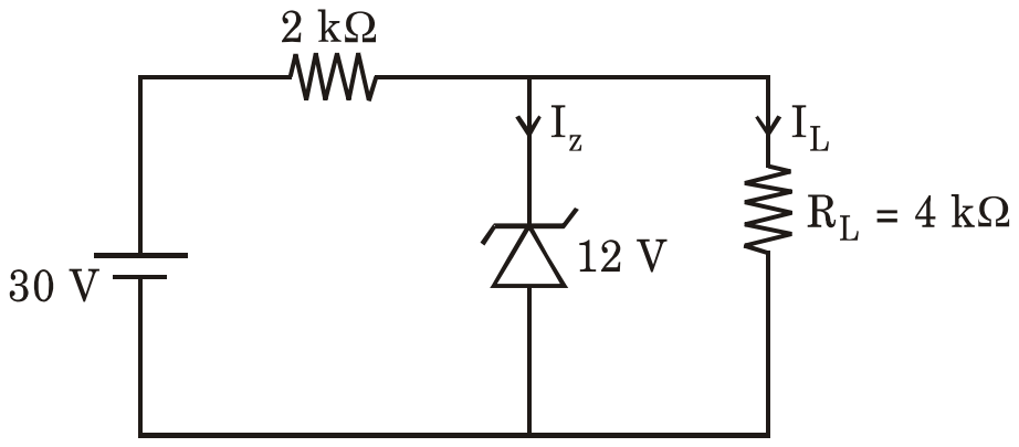
In the following Zener regulator circuit, the current through Zener diode Iz is equal to :

A 30 V source in series with a 2 kilo-ohm resistor feeds a 12 V Zener diode carrying Iz in parallel with a load RL = 4 kilo-ohm carrying IL

Exam Year(s)

MH SET - 2018, SET Exam - 2018,

Answer: B

The Zener current is 6 mA.

First check that the Zener conducts: without it the load would see \( 30 \times \frac{4}{2 + 4} = 20 \) V, above 12 V, so the Zener is in breakdown and holds the load at 12 V.

\[ \begin{aligned} I &= \frac{30 - 12}{2\ \text{k}\Omega} = 9\ \text{mA} \\ I_{L} &= \frac{12}{4\ \text{k}\Omega} = 3\ \text{mA} \\ I_{z} &= 9 - 3 = 6\ \text{mA} \end{aligned} \]

9 mA would be the answer if the load current were forgotten, and 4, 8 and 10 mA do not satisfy the two current balances above.

Please log in or register to report this question.

Answer: C

The tunnel diode is useful because it exhibits a negative resistance characteristic in the region between peak current IP and valley current IV.

A tunnel diode is very heavily doped, so its depletion layer is extremely thin and electrons can tunnel through the barrier. As forward voltage rises, current first rises to a peak and then falls to a valley as the bands move out of alignment. In that falling region, current decreases while voltage increases, a negative resistance, which can cancel the losses of a tuned circuit and sustain oscillation or provide gain at microwave frequencies.

The diode is heavily, not lightly, doped. A negative resistance supplies power to the circuit rather than absorbing it, and a positive resistance in that region would make it useless as an oscillator.

Please log in or register to report this question.

128.

Peak inverse voltage of diodes in bridge rectifier is normally ............. times that of diodes in full wave rectifier with centre tap transformer.

Exam Year(s)

MH SET - 2019, SET Exam - 2019,

Answer: C

The PIV in a bridge rectifier is 0.5 times that in a centre-tap full wave rectifier.

In a centre-tap full wave rectifier, when one diode conducts, the other has the full secondary voltage across it: the peak of its half plus the peak on the conducting side, so its PIV is \(2V_{m}\), where \(V_{m}\) is the peak voltage of each half of the secondary.

In a bridge rectifier, the two non-conducting diodes are each connected across the secondary, through the conducting diodes, so each sees a PIV of only \(V_{m}\). The ratio is \(V_{m}/2V_{m} = 0.5\), one of the advantages of the bridge circuit. The answer 2 inverts the ratio.

Please log in or register to report this question.

129.

A silicon diode dissipates 5 W of power when the dc current of 2 Amp flows through it. The bulk resistance of the diode is :

Exam Year(s)

MH SET - 2019, SET Exam - 2019,

Answer: B

The bulk resistance is 0.9 Ω.

The voltage across the diode is \(V = P/I = 5/2 = 2.5\) V. A silicon diode needs about 0.7 V to overcome its barrier potential; the rest drops across its bulk resistance:

\[ r_{B} = \frac{2.5 - 0.7}{2} = \frac{1.8}{2} = 0.9\ \Omega \]

The option 1.2 Ω uses V/I = 2.5/2 without subtracting the barrier potential (and rounds it down), and 2.5 Ω confuses volts with ohms.

Please log in or register to report this question.

130.

In a power supply circuit, the a.c. voltage of 100-0-100 Volts r.m.s. is applied to diodes of the full wave rectifier circuit. The output of the diodes is connected to a load of 5 kΩ. The D.C. current through the load resistance of 5 kΩ is nearly :

Exam Year(s)

MH SET - 2019, SET Exam - 2019,

Answer: B

The load current is nearly 18 mA.

In the centre-tapped full-wave rectifier, each half of the secondary gives 100 V r.m.s., a peak of \(V_{m} = 100\sqrt{2} = 141.4\) V. The average output of a full-wave rectifier is:

\[ \begin{aligned} V_{dc} &= \frac{2V_{m}}{\pi} = \frac{2 \times 141.4}{\pi} \\ &\approx 90\ \text{V} \end{aligned} \]

so \(I_{dc} = 90/5000 = 18\) mA. Using the r.m.s. value of 100 V would give 20 mA, and using the full 200 V across both halves would double the answer.

Please log in or register to report this question.

Loading…
Tags: Diode Circuits and Applications Questions and Answers || Diode Circuits and Applications MCQ Questions and Answers || Diode Circuits and Applications GK Questions and Answers || Diode Circuits and Applications GK MCQ Questions || Diode Circuits and Applications Multiple Choice Questions and Answers || Diode Circuits and Applications GK || GK on Diode Circuits and Applications || Analog Electronics Questions and Answers || Analog Electronics MCQ Questions and Answers || Analog Electronics GK Questions and Answers || GK on Analog Electronics