Machine-translated by Google. Questions are authored in English.
Top

Transfer Function and Block Diagrams Questions and Answers

1.

Parallel blocks with transfer functions \(G_1(s)\) and \(G_2(s)\) can be replaced by a single block with transfer function equal to ______.

Exam Year(s)

DSSSB AE - 2023,

Answer: A

When two blocks are in parallel, they receive the same input and their outputs are added at a summing point, so the overall transfer function is the sum.


\[ G(s) = G_1(s) + G_2(s) \]


The product \(G_1(s)G_2(s)\) is the result for blocks in cascade (series). The ratio \(G_1/G_2\) does not correspond to any simple connection, and \(\dfrac{G_1 G_2}{G_1 + G_2}\) is the form of two resistors in parallel, not of transfer functions in parallel. The answer is option A.

Please log in or register to report this question.

2.

What is the transfer function of the given open loop system with zero initial condition?

RC circuit: input voltage ei(t) in series with a resistor R carrying current i(t), with a capacitor C across the output eo(t)

Exam Year(s)

DSSSB AE - 2023,

Answer: A

The circuit is a series resistor with a capacitor across the output, the first order RC low pass circuit. With zero initial conditions, in the Laplace domain the capacitor has the impedance \(1/(Cs)\), so the output is a potential divider.


\[ \begin{aligned} \frac{E_o(s)}{E_i(s)} = \frac{1/(Cs)}{R + 1/(Cs)} \\ &= \frac{1}{RCs + 1} \end{aligned} \]


The pole is at \(s = -1/RC\) and the dc gain is 1. The option \(1/(RCs)\) is the transfer function of an integrator, and \(RCs + 1\) and \(RCs - 1\) are not transfer functions of this circuit, since they would increase with frequency. The answer is option A.

Please log in or register to report this question.

3.

The unit step response of a system is given.

\(Y(t) = 1 - (7/3)e^{-t} + (3/2)e^{-2t} - (1/6)e^{-4t}\)

What is its transfer function?

Exam Year(s)

DSSSB AE - 2023,

Answer: A

Take the Laplace transform of the step response, then divide by the transform of the unit step, \(1/s\).


\[ \begin{aligned} Y(s) \\ &= \frac{1}{s} - \frac{7/3}{s+1} + \frac{3/2}{s+2} - \frac{1/6}{s+4} \end{aligned} \]


\[ \begin{aligned} H(s) = sY(s) \\ &= 1 - \frac{7s}{3(s+1)} + \frac{3s}{2(s+2)} - \frac{s}{6(s+4)} \end{aligned} \]


Putting this over a common denominator gives \(H(s) = \dfrac{s + 8}{(s+1)(s+2)(s+4)}\). A check at \(s = 0\): the dc gain is \(8/8 = 1\), which matches the final value of the step response, \(y(\infty) = 1\). Also the residue of \(Y(s)\) at \(s = -1\) is \(H(-1)/(-1) = -7/3\), which agrees with the coefficient of \(e^{-t}\). The answer is option A.

Please log in or register to report this question.
4.

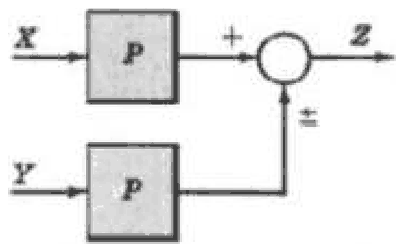
For the given block diagram, which of the following options is a correct replacement for moving a summing point ahead of a block?

Block diagram: input X into a block P, then a summing point adding Y (with plus or minus sign) to give output Z

Exam Year(s)

DSSSB AE - 2023,

Answer: B

The original diagram has the block \(P\) before the summing point: \(Z = PX \pm Y\). To move the summing point ahead of (before) the block, the signal \(Y\) that is added after \(P\) must be divided by \(P\) so that it has the same effect once it goes through the block.


\[ Z = P\left(X \pm \frac{Y}{P}\right) = PX \pm Y \]


So the correct replacement is to put the block \(1/P\) in the path of \(Y\), then sum with \(X\), and then pass the sum through \(P\), which is figure (B). In figure (A) the second \(P\) multiplies \(Y\) by \(P\), giving \(PX \pm PY\), which is wrong. In (C) the output is \(P(X \pm Y) \ne PX \pm Y\). Figure (D) is the rule for moving a take-off point, not a summing point. The answer is option B.

Please log in or register to report this question.

5.

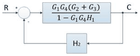
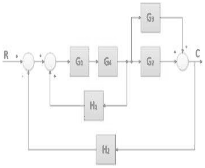
Which of the following options is the correct reduced block diagram (complete reduction) of the given block diagram?

Block diagram: input R, two summing points, blocks G1 and G4 in series, then a parallel pair G3 and G2 summed to give output C, with feedback H1 around G1, G4 and the take-off, and feedback H2 from C to the first summing point

Exam Year(s)

DSSSB AE - 2023,

Answer: D

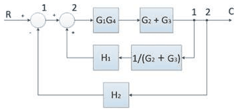
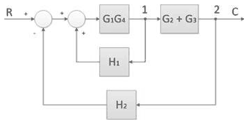
Reduce the diagram step by step. The blocks \(G_2\) and \(G_3\) are in parallel, so they combine to \(G_2 + G_3\), and the blocks \(G_1\) and \(G_4\) in series combine to \(G_1G_4\).


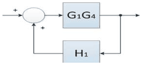
The feedback path \(H_1\) is taken from a point before the block \(G_2 + G_3\). Moving that take-off point after the block means that \(H_1\) must be divided by \(G_2 + G_3\), giving the inner loop with forward gain \(G_1G_4(G_2 + G_3)\) and feedback \(H_1/(G_2 + G_3)\), with positive feedback.


\[ \begin{aligned} \frac{G_1G_4(G_2 + G_3)}{1 - G_1G_4(G_2 + G_3)\cdot\dfrac{H_1}{G_2 + G_3}} \\ &= \frac{G_1G_4(G_2 + G_3)}{1 - G_1G_4H_1} \end{aligned} \]


This is a single block with the outer feedback \(H_2\) around it, which is figure (D). Figures (A) and (B) are intermediate stages, not the complete reduction, and (C) leaves out \(G_2 + G_3\) and \(H_2\). The answer is option D.

Please log in or register to report this question.

6.

The response of a system is obtained as \(C(t) = 1 + 0.2\exp(-60t) - 1.2\exp(-10t)\), when subjected to a unit-step input. The close loop transfer function is:

Exam Year(s)

DSSSB AE - 2023,

Answer: C

Take the Laplace transform of the step response and divide by the transform of the unit step, \(1/s\).


\[ \begin{aligned} C(s) \\ &= \frac{1}{s} + \frac{0.2}{s + 60} - \frac{1.2}{s + 10} \end{aligned} \]


The common denominator is \(s(s + 10)(s + 60)\), and the numerator works out to \(600\):


\[ \begin{aligned} \frac{(s+10)(s+60) + 0.2s(s+10) - 1.2s(s+60)}{s(s+10)(s+60)} \\ &= \frac{600}{s(s+10)(s+60)} \end{aligned} \]


\[ \begin{aligned} \frac{C(s)}{R(s)} = sC(s) \\ &= \frac{600}{(s + 10)(s + 60)} \\ &= \frac{600}{s^2 + 70s + 600} \end{aligned} \]


The dc gain is \(600/600 = 1\), matching the final value 1. The answer is option C.

Please log in or register to report this question.

7.

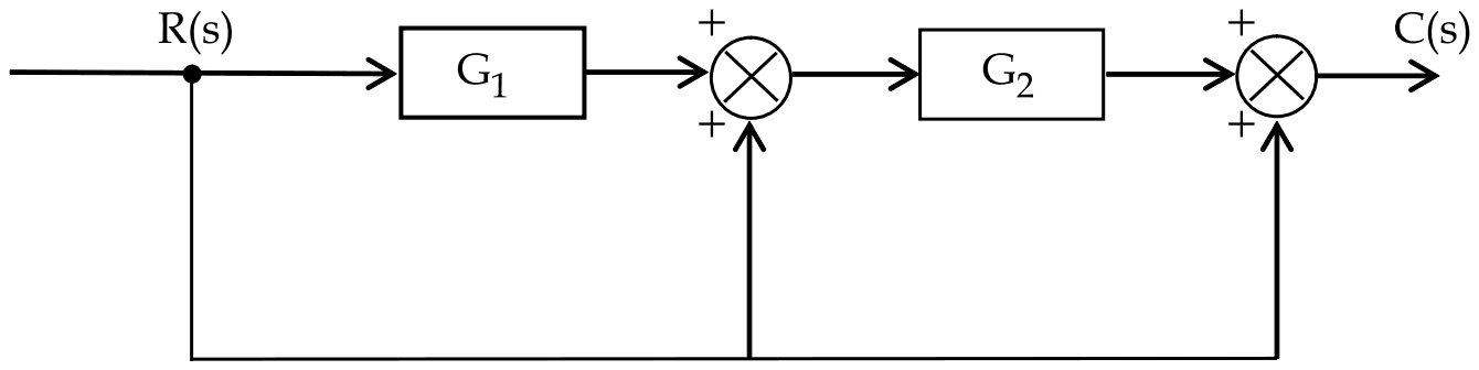
The transfer function \(\left(\frac{C(s)}{R(s)}\right)\) of the system shown in figure below is :

Block diagram: R(s) passes through G1 to a summing point, then through G2 to a second summing point whose output is C(s); R(s) is also fed directly to each summing point, all signs plus

Exam Year(s)

RSMSSB JE - 2025, RSMSSB - 2025,

Answer: A

The transfer function is \(1 + G_{2} + G_{1}G_{2}\).

Follow the signal forward. The first summing point adds R(s) to the output of \(G_{1}\), so its output is \(R(1 + G_{1})\). This passes through \(G_{2}\), and the second summing point adds R(s) once more:

\[ \begin{aligned} C &= G_{2}R(1 + G_{1}) + R \\ &= R(1 + G_{2} + G_{1}G_{2}) \end{aligned} \]

There is no feedback loop, only feedforward paths, so the result has no denominator, which rules out the two fractional options. \(1 + G_{1} + G_{2} + G_{1}G_{2}\) would need a direct path through \(G_{1}\) alone to the output, which the diagram does not have.

Please log in or register to report this question.
8.

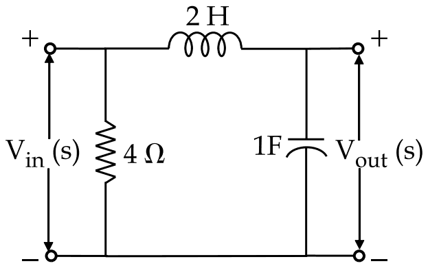
The voltage transfer function of the network shown in the figure below is :

Vin(s) across a 4 ohm resistor, a 2 H inductor in series from its upper terminal to the output, and a 1 F capacitor across the output where Vout(s) is taken

Exam Year(s)

RSMSSB JE - 2025, RSMSSB - 2025,

Answer: C

The transfer function is \(\frac{1}{1 + 2s^{2}}\).

The 4 Ω resistor is connected directly across the input, so it carries its own current but does not change the voltage applied to the rest of the network. The output is then a voltage divider of the 2 H inductor and the 1 F capacitor:

\[ \begin{aligned} \frac{V_{out}}{V_{in}} &= \frac{1/sC}{sL + 1/sC} = \frac{1}{1 + s^{2}LC} \\ &= \frac{1}{1 + 2s^{2}} \end{aligned} \]

\(\frac{1}{1 + 2s}\) would come from a resistor and capacitor, not an inductor and capacitor. \(1 + 4s\) and \(6 - s\) grow with frequency, which a passive divider of this kind cannot do.

Please log in or register to report this question.
9.

A feedback control system has open loop transfer function is :

\[ G(s) = \frac{5(s+3)(s+5)}{s^{2}(s+1)(s^{2}+7s+12)} \]

The system order and type number respectively is :

Exam Year(s)

RSMSSB JE - 2025, RSMSSB - 2025,

Answer: B

The order and type are 5 and 2.

The order is the highest power of \(s\) in the denominator of the transfer function. Here the denominator is \(s^{2}(s+1)(s^{2} + 7s + 12)\), of degree \(2 + 1 + 2 = 5\).

The type is the number of open-loop poles at the origin, the power of the factor \(s\) alone in the denominator: \(s^{2}\), so type 2. A type 2 system has zero steady-state error to step and ramp inputs.

The options with order 2 count only the \(s^{2}\) factor, and 2, 5 gives the two numbers in the wrong order.

Please log in or register to report this question.
Answer: A

The characteristic equation is formed by equating to zero the denominator of the transfer function.

For a closed-loop system with transfer function G(s)/(1 + G(s)H(s)), the characteristic equation is 1 + G(s)H(s) = 0. Its roots are the poles of the closed-loop system, which determine stability and the nature of the response.

Setting the numerator to zero gives the zeros of the system, not its characteristic equation. Equating numerator and denominator, or setting both to zero, has no such meaning.

Please log in or register to report this question.
Loading…

Other Subjects

Tags: Transfer Function and Block Diagrams Questions and Answers || Transfer Function and Block Diagrams MCQ Questions and Answers || Transfer Function and Block Diagrams GK Questions and Answers || Transfer Function and Block Diagrams GK MCQ Questions || Transfer Function and Block Diagrams Multiple Choice Questions and Answers || Transfer Function and Block Diagrams GK || GK on Transfer Function and Block Diagrams || Control Systems Questions and Answers || Control Systems MCQ Questions and Answers || Control Systems GK Questions and Answers || GK on Control Systems